Cisco 7609-S Installation Manual
Installation guide
Hide thumbs
Also See for 7609-S:
- User manual (22 pages) ,
- Configuration manual (1011 pages) ,
- Installation manual (324 pages)
Table of Contents
Advertisement
Quick Links
Advertisement
Table of Contents
Troubleshooting

Related Manuals for Cisco 7609-S


Summary of Contents for Cisco 7609-S
- Page 1 Cisco 7609 Internet Router Installation Guide September 2004 Corporate Headquarters Cisco Systems, Inc. 170 West Tasman Drive San Jose, CA 95134-1706 http://www.cisco.com Tel: 408 526-4000 800 553-NETS (6387) Fax: 408 526-4100 Customer Order Number: DOC-7812797= Text Part Number: OL-5079-04...
- Page 2 You can determine whether your equipment is causing interference by turning it off. If the interference stops, it was probably caused by the Cisco equipment or one of its peripheral devices. If the equipment causes interference to radio or television reception, try to correct the interference by using one or more of the following measures: •...
-
Page 3: Table Of Contents
C H A P T E R Warning # 1017 Cisco 7609 Internet Router System Features Bandwidth and Port Density Redundancy Component Hot Swapping Cisco 7600 Internet Router Components Fan Assembly Power Supplies Cisco 7609 Internet Router Installation Guide OL-5079-04... - Page 4 System Ground Connection 3-12 Required Tools and Equipment 3-12 Connecting the System Ground 3-14 Installing the Power Supplies in the Cisco 7609 Chassis 3-14 Attaching the Interface Cables 3-15 Connecting the Supervisor Engine Console Port 3-15 Connecting the Supervisor Engine Uplink Ports...
- Page 5 Checking the Installation 5-15 Technical Specifications A P P E N D I X Cisco 7609 Internet Router Cisco 7609 Internet Router Power Supplies Regulatory Standards Compliance Connector and Cable Specifications A P P E N D I X Connector Specifications...
- Page 6 Console Port Mode 1 Signaling and Pinouts Console Port Mode 2 Signaling and Pinouts B-12 Mode-Conditioning Patch Cord B-13 Repacking the Cisco 7609 Internet Router A P P E N D I X I N D E X Cisco 7609 Internet Router Installation Guide OL-5079-04...
-
Page 7: Preface
Preface This document describes the Cisco 7609 Internet Router (OSR-7609) and not Note the Cisco 7609 Internet Router (CISCO7609). This preface describes who should read the Cisco 7609 Internet Router Installation Guide, how it is organized, and its document conventions. -
Page 8: Conventions
Preparing for Installation Describes how to prepare your site for the installation of the Cisco 7609 Internet Router. Chapter 3 Installing the Cisco 7609 Describes how to install your Cisco 7609 Internet Internet Router Router Chapter 4 Troubleshooting Provides troubleshooting guidelines for the initial... - Page 9 Preface Conventions Cautions use the following conventions: Means reader be careful. In this situation, you might do something that could Caution result in equipment damage or loss of data. Cisco 7609 Internet Router Installation Guide OL-5079-04...
- Page 10 Ennen kuin työskentelet minkään laitteiston parissa, ota selvää sähkökytkentöihin liittyvistä vaaroista ja tavanomaisista onnettomuuksien ehkäisykeinoista. Tässä julkaisussa esiintyvien varoitusten käännökset löydät laitteen mukana olevasta Regulatory Compliance and Safety Information -kirjasesta (määräysten noudattaminen ja tietoa turvallisuudesta). Cisco 7609 Internet Router Installation Guide OL-5079-04...
- Page 11 La traduzione delle avvertenze riportate in questa pubblicazione si trova nel documento Regulatory Compliance and Safety Information (Conformità alle norme e informazioni sulla sicurezza) che accompagna questo dispositivo. Cisco 7609 Internet Router Installation Guide OL-5079-04...
- Page 12 Se förklaringar av de varningar som förkommer i denna publikation i dokumentet Regulatory Compliance and Safety Information (Efterrättelse av föreskrifter och säkerhetsinformation), vilket medföljer denna anordning. Cisco 7609 Internet Router Installation Guide OL-5079-04...
-
Page 13: Related Documentation
• http://www.cisco.com/public/sw-center/netmgmt/cmtk/mibs.shtml Obtaining Documentation The following sections provide sources for obtaining documentation from Cisco Systems. World Wide Web You can access the most current Cisco documentation on the World Wide Web at the following sites: http://www.cisco.com • http://www-china.cisco.com • http://www-europe.cisco.com •... -
Page 14: Documentation Cd-Rom
800 553-NETS(6387). Documentation Feedback If you are reading Cisco product documentation on the World Wide Web, you can submit technical comments electronically. Click Feedback in the toolbar and select Documentation. After you complete the form, click Submit to send it to Cisco. -
Page 15: Obtaining Technical Assistance
Customers and partners can obtain documentation, troubleshooting tips, and sample configurations from online tools by using the Cisco Technical Assistance Center (TAC) Web Site. Cisco.com registered users have complete access to the technical support resources on the Cisco TAC Web Site. -
Page 16: Technical Assistance Center
No workaround is available. Which Cisco TAC resource you choose is based on the priority of the problem and the conditions of service contracts, when applicable. Cisco TAC Web Site... - Page 17 Obtaining Technical Assistance If you cannot resolve your technical issues by using the Cisco TAC Web Site, and you are a Cisco.com registered user, you can open a case online by using the TAC Case Open tool at the following URL: http://www.cisco.com/tac/caseopen...
- Page 18 Preface Obtaining Technical Assistance Cisco 7609 Internet Router Installation Guide xviii OL-5079-04...
-
Page 19: Product Overview
Cisco 7600 Internet Router Components, page 1-8 • The Cisco 7609 Internet Router delivers optical WAN and MAN networking with a focus on line-rate delivery of high-touch IP services at the edge of service providers networks. Service providers can “service enable” their networks at optical speeds, enabling them to differentiate their service offerings for competitive advantage. -
Page 20: Warning # 1017
Questa unità è prevista per essere installata in un'area ad accesso limitato, vale a dire un'area accessibile solo mediante l'uso di un attrezzo speciale, come lucchetto e chiave, o altri dispositivi di sicurezza. Cisco 7609 Internet Router Installation Guide OL-5079-04... - Page 21 Varning! Denna enhet är avsedd för installation i områden med begränsat tillträde. Ett område med begränsat tillträde kan endast tillträdas med hjälp av specialverktyg, lås och nyckel eller annan säkerhetsanordning. Cisco 7609 Internet Router Installation Guide OL-5079-04...
-
Page 22: Cisco 7609 Internet Router
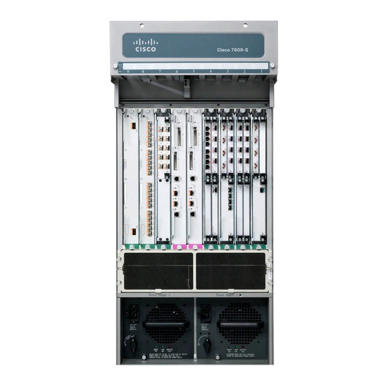
Chapter 1 Product Overview Cisco 7609 Internet Router Cisco 7609 Internet Router The Cisco 7609 Internet Router chassis has nine vertical slots that are numbered from right to left. (See Figure 1-1.) Slot 1 is reserved for the supervisor engine, which provides switching, local and remote management, and multiple gigabit uplink interfaces. - Page 23 Redundant supervisor engine Switch Fabric Module Redundant Switch Fabric Module Slots 1-9 (right to left) INPUT OUTPUT FAIL INPUT OUTPUT FAIL Power supply 2 Power supply 1 (redundant) ESD ground strap connection Cisco 7609 Internet Router Installation Guide OL-5079-04...
-
Page 24: System Features
Redundant AC-input or DC-input power supplies • System Features This section describes the hardware features for the Cisco 7609 Internet Router. For software descriptions, refer to the Cisco 7600 Series Internet Router Software Configuration Guide. For module descriptions and installation procedures, refer to the Cisco 7600 Series Internet Router Module Installation Guide. -
Page 25: Redundancy
Number of channelized OC-12 ports Number of channelized OC-48 ports Number of FlexWAN modules Redundancy The Cisco 7609 Internet Router has these redundancy features: Ability to house two hot-swappable supervisor engines • Ability to house two fully redundant, AC-input or DC-input, load-sharing •... -
Page 26: Component Hot Swapping
The fan assembly is located in the chassis. Figure 1-2 shows the direction of airflow into and out of the Cisco 7609 Internet Router. Sensors on the supervisor engine monitor the internal air temperatures. If the air temperature exceeds a preset threshold, the environmental monitor displays warning messages. -
Page 27: Power Supplies
OUTPUT FAIL INPUT OUTPUT FAIL Power Supplies The Cisco 7609 Internet Router power supplies are available in two power ratings: 2500W—AC and DC input (WS-CAC-2500W and WS-CDC-2500W) • 4000W—AC input only (WS-CAC-4000W-US1 or WS-CAC-4000W-INT) • All power supplies have the same form factor. - Page 28 If you run the 2500W power supply at the low range input (100 to 120VAC), Note it is not redundant in a fully populated Cisco 7609 Internet Router. For complete power specifications, see Appendix A, “Technical Specifications.”...
-
Page 29: Load Sharing
OUTPUT FAIL indications on the power supply. For information about the power management feature and individual module power consumption, refer to the Cisco 7600 Series Internet Router Software Configuration Guide. Cisco 7609 Internet Router Installation Guide... - Page 30 The power supply front panel LEDs are described in Table 1-2. For more information about the environmental monitoring feature, refer to the Cisco 7600 Series Internet Router Software Configuration Guide. Table 1-2 Power Supply Front Panel LEDs Description INPUT OK...
- Page 31 An air dam keeps the airflow separate from the rest of the chassis, which is cooled by the system fan assembly. To replace a power supply, see the “Removing and Replacing the Power Supply” section on page 5-2. Cisco 7609 Internet Router Installation Guide 1-13 OL-5079-04...
- Page 32 Chapter 1 Product Overview Cisco 7600 Internet Router Components Cisco 7609 Internet Router Installation Guide 1-14 OL-5079-04...
-
Page 33: Preparing For Installation
This document describes the Cisco 7609 Internet Router (OSR-7609) and not Note the Cisco 7609 Internet Router (CISCO7609). This chapter describes how to prepare your site for Cisco 7609 Internet Router (OSR-7609) installation and contains these sections: Safety, page 2-1 •... -
Page 34: Site Requirements
Site Requirements Site Requirements This section provides site power requirements for the Cisco 7609 Internet Router. You should verify the site power prior to installing the switch. Power requirements vary for each switch; ensure that you verify the site power for the type of switch you are installing. - Page 35 2.80 2.10 1.40 1.05 OC-3 POS, 16-port OSM-2OC12-ATM-MM, 2.11 1.58 1.06 0.79 OC-12 ATM, 2-port OSM-2OC12-ATM-MM+, 2.33 1.75 1.17 0.88 -SI+ OC-12 ATM, 2-port OSM-1OC48-POS-SS, -SI, 2.48 1.86 1.24 0.93 OC-48 POS, 1-port Cisco 7609 Internet Router Installation Guide OL-5079-04...
- Page 36 WS-X6500-SFM2 1.80 1.35 0.90 0.68 Switch Fabric Module 2 WS-X6182-2PA 1.39 1.04 0.69 0.52 FlexWAN module WS-X6348-RJ-45 1.39 1.05 0.70 0.52 10/100BASE-TX, 48-port WS-X6516-GBIC 1.98 1.49 0.99 0.74 1000BASE-X (SX, LX/LH, ZX), 16-port Cisco 7609 Internet Router Installation Guide OL-5079-04...
- Page 37 5.99 4.79 OC-3 POS, 16-port OSM-16OC3-POS-SI+ 5.65 4.52 OC-3 POS, 16-port OSM-2OC12-ATM-MM, -SI 4.26 3.41 OC-12 ATM, 2-port OSM-2OC12-ATM-MM+, -SI+ 4.70 3.76 OC-12 ATM, 2-port OSM-1OC48-POS-SS, -SI, -SL 5.00 4.00 OC-48 POS, 1-port Cisco 7609 Internet Router Installation Guide OL-5079-04...
- Page 38 Switch Fabric Module 2 WS-X6182-2PA 2.80 2.24 FlexWAN module WS-X6348-RJ-45 2.81 2.85 10/100BASE-TX, 48-port WS-X6516-GBIC 4.00 3.20 1000BASE-X (SX, LX/LH, ZX), 16-port 1. DPT = Dynamic Packet Transport 2. GBICs = Gigabit Interface Converters Cisco 7609 Internet Router Installation Guide OL-5079-04...
- Page 39 Preparing for Installation Site Requirements Table 2-4 provides a sample calculation of power and heat dissipation for the following switch configuration: Cisco 7609 Internet Router chassis (including AC-input power supplies) • • Two WS-X6K-S2U-MSFC2 supervisor engines One Switch Fabric Module •...
-
Page 40: Power Requirements
Use the information in Table 2-2 to estimate the power requirements and heat dissipation of a Cisco 7609 Internet Router based on a given configuration of the switch. Table 2-4 provides a sample calculation. Determining power requirements might be useful for planning the power distribution system needed to support the switch. -
Page 41: Ac-Powered Systems
2500W power supply power cord. Table 2-5 lists the AC-input power cord options and Cisco product numbers. 4000W—Figure 2-2 shows the two different styles of AC-input power cord •... - Page 42 IEC 320 (16/20A) Figure 2-2 AC Power Cord Connectors for the 4000W Power Supply International North America (Locking) (4000W power supply) (4000W power supply) IEC 60309 (30A, 250V) NEMA L6-30 plug (30A, 250V) Cisco 7609 Internet Router Installation Guide 2-10 OL-5079-04...
-
Page 43: Dc-Powered Systems
(DC-I). Site Preparation Checklist Table 2-6 lists the site planning activities that you should perform prior to installing the Cisco 7609 Internet Router. Completing each activity helps ensure a successful switch installation. Cisco 7609 Internet Router Installation Guide 2-11 OL-5079-04... - Page 44 Circuit breaker size CO ground (AC- and DC-powered systems) Cable and interface equipment evaluation: Cable type Connector type Cable distance limitations Interface equipment (transceivers) EMI evaluation: Distance limitations for signaling Site wiring RFI levels Cisco 7609 Internet Router Installation Guide 2-12 OL-5079-04...
-
Page 45: Installing The Cisco 7609 Internet Router
This document describes the Cisco 7609 Internet Router (OSR-7609) and not Note the Cisco 7609 Internet Router (CISCO7609). This chapter describes how to install a Cisco 7609 Internet Router (OSR-7609) in a rack. For first-time installations, perform the procedures in the following sections in the order listed: Unpacking the Cisco 7609 Internet Router, page 3-2 •... -
Page 46: Unpacking The Cisco 7609 Internet Router
Do not discard the shipping container when you unpack the Cisco 7609 Internet Router. Flatten the shipping cartons and store them with the pallet. You will need these containers if you need to move or ship the Cisco 7609 Internet Router in the future. Repacking instructions are provided in Appendix C, “Repacking the Cisco 7609 Internet Router.”... -
Page 47: Installing The Rack-Mount Kit
19.25 inches (48.9 cm) but not more than 32 inches (81.3 cm). • The rack must have sufficient vertical clearance to insert the chassis. The chassis height for the Cisco 7609 Internet Router is 33.5 inches (85.1 cm) (20 RU). Cisco 7609 Internet Router Installation Guide OL-5079-04... -
Page 48: Required Tools
Chapter 3 Installing the Cisco 7609 Internet Router Installing the Rack-Mount Kit Chassis height is measured in rack units (RU). Note If the rack is on wheels, ensure that the brakes are engaged or that the rack is Caution otherwise stabilized. - Page 49 Chapter 3 Installing the Cisco 7609 Internet Router Installing the Rack-Mount Kit Figure 3-1 Installing the Shelf Brackets Shelf bracket Shelf bracket 12-24 x 3/4-inch 10-32 x 3/4-inch screw (6x) Figure 3-2 Attaching the Crossbar Bracket to the Shelf Brackets...
-
Page 50: Installing The L Brackets And Cable Guides
Installing the L Brackets and Cable Guides The Cisco 7609 Internet Router L bracket screw holes are stamped + and –. You can install the brackets either on the left or right side of the chassis; use the + holes on one side and the –... - Page 51 Chapter 3 Installing the Cisco 7609 Internet Router Installing the Rack-Mount Kit Figure 3-3 Attaching L Brackets and Cable Guides L bracket L bracket STATUS Cable guide M4 screws Cisco 7609 Internet Router Installation Guide OL-5079-04...
-
Page 52: Installing The Cisco 7609 Chassis In The Rack
Installing the Cisco 7609 Internet Router Installing the Cisco 7609 Chassis in the Rack Installing the Cisco 7609 Chassis in the Rack If you are not installing the Cisco 7609 Internet Router in the rack, you must Note install the stabilizer kit. See “Installing the Stabilizer Kit”... - Page 53 Chapter 3 Installing the Cisco 7609 Internet Router Installing the Cisco 7609 Chassis in the Rack Figure 3-4 Installing the Cisco 7609 Chassis in the Rack bracket INPUT OUTP UT FAIL INPUT OUTP UT FAIL Crossbar bracket Shelf bracket Install the eight or ten (four or five per side) 12-24 x 3/4-inch or 10-32 x 3/4-inch...
-
Page 54: Installing The Stabilizer Kit
Note Internet Router. If you are not installing the Cisco 7609 Internet Router in a rack, you must install stabilizer brackets to the bottom of the chassis. The stabilizer brackets reduce the possibility that the freestanding chassis will tip over. - Page 55 Chapter 3 Installing the Cisco 7609 Internet Router Installing the Stabilizer Kit Figure 3-5 Installing the Stabilizer Brackets STATUS Tilt the chassis to the other side. Step 3 Attach the second stabilizer bracket to the other side of the chassis with eight M4 Step 4 screws.
-
Page 56: System Ground Connection
Installing the Cisco 7609 Internet Router System Ground Connection System Ground Connection This section describes how to connect a system (earth) ground to the Cisco 7609 Internet Router. Note You must connect both the system ground connection and the power supply ground connection to an earth ground. - Page 57 Chapter 3 Installing the Cisco 7609 Internet Router System Ground Connection Wire-stripping tool • Figure 3-6 System Ground Location INPUT OUTP UT INPUT FAIL OUTP UT INPUT FAIL OUTP UT INPUT FAIL OUTP UT FAIL Grounding pad location under lip...
-
Page 58: Connecting The System Ground
Prepare the other end of the grounding wire and connect it to an appropriate Step 7 grounding point in your site to ensure adequate earth ground for the Cisco 7609 Internet Router. Installing the Power Supplies in the Cisco 7609... -
Page 59: Attaching The Interface Cables
Depending on the modules you have installed in your chassis, you will have different styles of connectors to attach. Note Refer to the Cisco 7600 Series Internet Router Module Installation Guide for additional module information. Connecting the Supervisor Engine Console Port This section describes how to connect to the supervisor engine console port from a terminal or modem. - Page 60 MO DE C O N SO LE SU PE R VI SO R The accessory kit that shipped with your Cisco 7609 Internet Router contains Note the necessary cable and adapters to connect a terminal or modem to the console port.
- Page 61 Chapter 3 Installing the Cisco 7609 Internet Router Attaching the Interface Cables To connect a terminal using a Catalyst 5000 family Supervisor Engine III console cable, perform these steps: Step 1 Place the console port mode switch in the out position.
-
Page 62: Connecting The Supervisor Engine Uplink Ports
Chapter 3 Installing the Cisco 7609 Internet Router Attaching the Interface Cables Connecting the Supervisor Engine Uplink Ports This section describes how to connect to the supervisor engine uplink ports. Because invisible laser radiation may be emitted from the aperture of the... -
Page 63: Connector Specifications
Chapter 3 Installing the Cisco 7609 Internet Router Attaching the Interface Cables When you plug the SC-type connector into the GBIC, make sure that Note both the transmit (Tx) and receive (Rx) fiber-optic cables are fully inserted into the SC-type connector. - Page 64 Chapter 3 Installing the Cisco 7609 Internet Router Attaching the Interface Cables Figure 3-10 LC Fiber-Optic Connector Figure 3-11 MT-RJ Fiber-Optic Connector Figure 3-12 RJ-45 Connectors Cisco 7609 Internet Router Installation Guide 3-20 OL-5079-04...
-
Page 65: Verifying Cisco 7609 Chassis Installation
After you finish connecting the modules, you need to verify that the modules, power supplies, and fan assembly are correctly and securely installed. To verify the Cisco 7609 chassis installation, perform these steps: Verify that the ejector levers of each module are fully closed (parallel to the... - Page 66 Chapter 3 Installing the Cisco 7609 Internet Router Verifying Cisco 7609 Chassis Installation Cisco 7609 Internet Router Installation Guide 3-22 OL-5079-04...
-
Page 67: Troubleshooting
C H A P T E R Troubleshooting This document describes the Cisco 7609 Internet Router (OSR-7609) and not Note the Cisco 7609 Internet Router (CISCO7609). This chapter describes how to troubleshoot the Cisco 7609 Internet Router (OSR-7609) hardware installation and contains these sections: Getting Started, page 4-2 •... -
Page 68: Getting Started
Cisco 7600 Series Internet Router Software Configuration Guide, the Cisco 7600 Series Internet Router IOS Software Configuration Guide, the Cisco 7600 Series Internet Router Command Reference, or the Cisco 7600 Series Internet Router IOS Command Reference publications to troubleshoot the software. -
Page 69: Identifying Startup Problems
LEDs on the supervisor engine indicate whether or not the supervisor engine is able to initialize the switching module. If you have a redundant supervisor engine, refer to the Cisco 7600 Series Internet Router Software Configuration Guide or the Cisco 7600 Series... - Page 70 “Troubleshooting Modules” section on page 4-6. If you have a redundant supervisor engine, refer to the Cisco 7600 Series Internet Router Software Configuration Guide or the Cisco 7600 Series Internet Router IOS Software Configuration Guide publications for descriptions of how the redundant supervisor engine comes online and how the software images are handled.
-
Page 71: Troubleshooting The Power Supply
Step 2 supply. If you are unable to resolve the problem or if you determine that either a power supply or backplane connector is faulty, see the “Contacting Customer Service” section on page 4-7. Cisco 7609 Internet Router Installation Guide OL-5079-04... -
Page 72: Troubleshooting The Fan Assembly
Reseat the module until both ejector levers are at 90 degrees to the rear of the chassis. Tighten the captive installation screws at the left and right of the module front panel, and restart the system. Cisco 7609 Internet Router Installation Guide OL-5079-04... -
Page 73: Contacting Customer Service
Refer to the Cisco 7600 Series Internet Router Software Configuration Guide, the Cisco 7600 Series Internet Router IOS Software Configuration Guide, the Cisco 7600 Series Internet Router Command Reference or the Cisco 7600 Series Internet Router IOS Command Reference publications to configure or enable the interfaces. - Page 74 Chapter 4 Troubleshooting Contacting Customer Service Cisco 7609 Internet Router Installation Guide OL-5079-04...
-
Page 75: Removal And Replacement Procedures
C H A P T E R Removal and Replacement Procedures This document describes the Cisco 7609 Internet Router (OSR-7609) and not Note the Cisco 7609 Internet Router (CISCO7609). This chapter describes how to perform the following removal and replacement... -
Page 76: Removing And Replacing The Power Supply
Figure 5-1.) Turning the power switch to the Off (0) position also disengages a pawl that unlocks the power supply from the chassis. Disconnect the power cord from the power source. Step 2 Cisco 7609 Internet Router Installation Guide OL-5079-04... - Page 77 Loosen the captive installation screw. (See Figure 5-1.) Step 4 Use both hands to install and remove power supplies. Each Cisco 7609 Caution Internet Router AC-input power supply weighs between 22 pounds (9.9 kg) and 28 pounds (12.6 kg). Grasp the power supply handle with one hand and slide the power supply part of Step 5 the way out of the chassis.
- Page 78 FAIL If the power supply bay is to remain empty, install a blank power supply filler Step 6 plate (Cisco part number 700-03104-01) over the opening and secure it with the captive installation screw. Cisco 7609 Internet Router Installation Guide...
-
Page 79: Installing An Ac-Input Power Supply
Removal and Replacement Procedures Removing and Replacing the Power Supply Installing an AC-Input Power Supply Use both hands to install and remove power supplies. Each Cisco 7609 Caution Internet Router AC-input power supply weighs between 22 pounds (9.9 kg) and 28 pounds (12.6 kg). -
Page 80: Removing A Dc-Input Power Supply
5-3.) Turning the power switch off also disengages a pawl that unlocks the power supply from the chassis. Remove the two screws securing the terminal block cover, and slide the cover off Step 3 the terminal block. (See Figure 5-3.) Cisco 7609 Internet Router Installation Guide OL-5079-04... - Page 81 Disconnect the DC-input wires from the terminal block (see Figure 5-4) in the following order: Positive (+) • Negative (–) • Ground • Warning When installing the unit, the ground connection must always be made first and disconnected last. Cisco 7609 Internet Router Installation Guide OL-5079-04...
- Page 82 Loosen the captive installation screw on the power supply. (See Figure 5-4.) Step 5 Use both hands to install and remove power supplies. Each Cisco 7609 Caution Internet Router DC-input power supply weighs between 22 pounds (9.9 kg) and 28 pounds (12.6 kg).
- Page 83 FAIL If the power supply bay is to remain empty, install a blank power supply filler Step 7 plate (Cisco part number 700-03104-01) over the opening, and secure it with the captive installation screw. Cisco 7609 Internet Router Installation Guide...
-
Page 84: Installing A Dc-Input Power Supply
Figure 5-3.) Caution Use both hands to install and remove power supplies. Each Cisco 7609 Internet Router DC-input power supply weighs between 22 pounds (9.9 kg) and 28 pounds (12.6 kg). Grasp the power supply handle with one hand and place your other hand Step 4 underneath the power supply. - Page 85 (+) Positive ( - ) Negative ( ) Ground Power switch INP UT FA N OU TP UT FA IL DC-input power supply with the terminal block cover removed Captive installation screw Cisco 7609 Internet Router Installation Guide 5-11 OL-5079-04...
-
Page 86: Removing And Replacing The Fan Assembly
Removing and Replacing the Fan Assembly This section describes how to remove and replace fan assemblies for the Cisco 7609 Internet Router. A flat-blade or number 2 Phillips-head screwdriver is required to perform this procedure. Cisco 7609 Internet Router Installation Guide... -
Page 87: Removing The Fan Assembly
Perform these steps to remove the existing fan assembly: Locate the fan assembly located above the card cage. (See Figure 5-7.) Step 1 Figure 5-7 Fan Assembly Captive installation screw STATUS Captive installation screw INPUT OUTPUT FAIL INPUT OUTPUT FAIL Cisco 7609 Internet Router Installation Guide 5-13 OL-5079-04... -
Page 88: Installing The Fan Assembly
Push the fan assembly into the chassis until the power connector seats in the Step 3 backplane and the captive installation screws make contact with the chassis. Tighten the captive installation screws. Step 4 Cisco 7609 Internet Router Installation Guide 5-14 OL-5079-04... -
Page 89: Checking The Installation
If after several attempts the fans do not operate or you experience trouble with the Step 3 installation (for instance, if the captive installation screws do not align with the chassis holes), contact a Cisco customer service representative for assistance. Cisco 7609 Internet Router Installation Guide 5-15... - Page 90 Chapter 5 Removal and Replacement Procedures Removing and Replacing the Fan Assembly Cisco 7609 Internet Router Installation Guide 5-16 OL-5079-04...
-
Page 91: Appendix
• Cisco 7609 Internet Router Power Supplies, page A-3 • Regulatory Standards Compliance, page A-4 • Refer to the Cisco 7600 Series Internet Router Module Installation Guide for module and interface port specifications. Cisco 7609 Internet Router Installation Guide OL-5079-04... -
Page 92: Cisco 7609 Internet Router
Appendix A Technical Specifications Cisco 7609 Internet Router Cisco 7609 Internet Router The Cisco 7609 Internet Router (OSR-7609) specifications are provided in Table A-1. Table A-1 Cisco 7609 Internet Router Specifications Item Specification Environmental Temperature, ambient operating 32°F (0°C) to 104°F (40°C) Temperature, ambient nonoperating and –40°F (–40°C) to 158°F (70°C) -
Page 93: Cisco 7609 Internet Router Power Supplies
Appendix A Technical Specifications Cisco 7609 Internet Router Power Supplies Cisco 7609 Internet Router Power Supplies Table A-2 lists the specifications for the Cisco 7609 Internet Router power supplies. Table A-2 Cisco 7609 Internet Router Power Supply Specifications Item Specification... -
Page 94: Regulatory Standards Compliance
Output holdup time 20 ms minimum. Regulatory Standards Compliance The Cisco 7609 Internet Router complies with the regulatory standards listed in the Regulatory Compliance and Safety Information for the Cisco 7600 Series Internet Routers publication. Cisco 7609 Internet Router Installation Guide... -
Page 95: Appendix
Warning To reduce the risk of fire, use only No. 26 AWG or larger telecommunication line cord. Connector Specifications This section covers the types of connectors used with the Cisco 7609 Internet Router: RJ-45, page B-3 • MT-RJ, page B-3 •... - Page 96 Appendix B Connector and Cable Specifications Connector Specifications Gigabit Interface Converters, page B-6 • Cisco 7609 Internet Router Installation Guide OL-5079-04...
-
Page 97: Mt-Rj
The MT-RJ style connector, shown in Figure B-2, is used on fiber-optic modules to increase port density. Figure B-2 MT-RJ Connector Cisco 7609 Internet Router Installation Guide OL-5079-04... - Page 98 Remove any residual dust from the faceplate with compressed air before installing the cable. Make sure that dust caps are installed on all unused module connectors and Note unused network fiber-optic cable connectors. Cisco 7609 Internet Router Installation Guide OL-5079-04...
-
Page 99: Sc-Type
The SC-type fiber connector, shown in Figure B-4, is used to connect fiber-optic module ports with the external network. Figure B-4 SC-Type Fiber-Optic Connector Cisco 7609 Internet Router Installation Guide OL-5079-04... -
Page 100: Gigabit Interface Converters
Product Number Short wavelength WS-G5484 (1000BASE-SX) Long wavelength/long haul WS-G5486 (1000BASE-LX/LH) Extended distance WS-G5487 (1000BASE-ZX) WS-G5484 The WS-G5484 GBIC (1000BASE-SX) operates on ordinary multimode fiber-optic link spans of up to 550 meters in length. Cisco 7609 Internet Router Installation Guide OL-5079-04... - Page 101 WS-G5487 GBIC at each end of the link whenever the fiber-optic cable span is equal to or greater than 25 km and less than 50 km. GBICs use an SC-type connector to link the module to the fiber-optic cable. Cisco 7609 Internet Router Installation Guide OL-5079-04...
-
Page 102: Cable Specifications
Cable Specifications Cable Specifications The Cisco 7609 Internet Router comes with an accessories box that contains the cable and adapters you need to connect a console (an ASCII terminal or PC running terminal emulation software) or modem to the console port. The... -
Page 103: Identifying A Rollover Cable
B-6.) If your cable was purchased from Cisco Systems, pin 1 will be white on one connector, and pin 8 will be white on the other. (A rollover cable reverses pins 1 and 8, 2 and 7, 3 and 6, and 4 and 5.) - Page 104 Use the RJ-45-to-RJ-45 rollover cable and RJ-45-to-DB-25 female DTE adapter (labeled “Terminal”) to connect the console port to a terminal. Table B-3 lists the pinouts for the asynchronous serial console port, the RJ-45-to-RJ-45 rollover cable, and the RJ-45-to-DB-25 female DTE adapter. Cisco 7609 Internet Router Installation Guide B-10 OL-5079-04...
-
Page 105: Modem Adapter
RJ-45-to-DB-25 male DCE adapter. Table B-4 Port Mode 1 Signaling and Pinouts (Modem Adapter) RJ-45-to-RJ-45 RJ-45-to-DB-25 Console Port Rollover Cable Modem Adapter Modem Signal RJ-45 Pin RJ-45 Pin DB-25 Pin Signal Cisco 7609 Internet Router Installation Guide B-11 OL-5079-04... -
Page 106: Console Port Mode 2 Signaling And Pinouts
Input/Output 1 (RTS) Output 2 (DTR) Output 3 (RxD) Input 4 (GND) 5 (GND) 6 (TxD) Output 7 (DSR) Input 8 (CTS) Input 1. Pin 1 is connected internally to Pin 8. Cisco 7609 Internet Router Installation Guide B-12 OL-5079-04... -
Page 107: Mode-Conditioning Patch Cord
Mode-Conditioning Patch Cord When using the long wavelength/long-haul (LX/LH) GBIC with 62.5-micron diameter MMF, you must install a mode-conditioning patch cord (Cisco product number CAB-GELX-625 or equivalent) between the GBIC and the multimode fiber (MMF) cable on both the transmit and receive ends of the link. -
Page 108: Patch Cord Installation
Ethernet communications at a gigabit-per-second rate. The specification offers a higher-speed version of Ethernet for backbone and server connectivity using existing deployed MMF cable by defining the use of laser-based optical components to propagate data over MMF cable. Cisco 7609 Internet Router Installation Guide B-14 OL-5079-04... - Page 109 (See Figure B-9.) Figure B-9 LED Transmission Compared to Laser Transmission LED transmission Laser transmission Laser Cisco 7609 Internet Router Installation Guide B-15 OL-5079-04...
- Page 110 (We do not recommend using the LX/LH GBIC and MMF without a patch cord for very short link distances of 33 to 328 feet (10 to 100 meters.) The result could be an elevated bit error rate [BER]). Cisco 7609 Internet Router Installation Guide B-16 OL-5079-04...
-
Page 111: Appendix
Note the Cisco 7609 Internet Router (CISCO7609). If you need to return or move the Cisco 7609 Internet Router (OSR-7609) chassis, follow these steps to repack the chassis using the original packaging material: Set the chassis in the bottom pallet. (See Figure C-1.) - Page 112 Appendix C Repacking the Cisco 7609 Internet Router Place the outside carton over the entire package. Step 7 Step 8 Fold the outside carton down over the top and seal with packing tape. Wrap three packing straps tightly around the top and bottom of the package to Step 9 hold the outside carton and the bottom pallet together.
- Page 113 Appendix C Repacking the Cisco 7609 Internet Router Figure C-2 Final Package Do not use tape to hold the outside carton to the bottom pallet. Packing straps Note must be added to hold the entire package together and to add strength to the package.
- Page 114 Appendix C Repacking the Cisco 7609 Internet Router Cisco 7609 Internet Router Installation Guide OL-5079-04...
- Page 115 B-11 installation procedure, AC-input airflow installation procedure, DC-input 5-10 Cisco 7609 Internet Router removal procedure, AC-input direction removal procedure, DC-input altitude, environmental specifications specifications Cisco 7609 Internet Router repacking Cisco 7609 Internet Router Installation Guide IN-1 OL-5079-04...
-
Page 116: Rj-45 B-
5-12 DC-input power supply features connecting system ground 3-14 bandwidth and port density installing 5-10 hot swapping LEDs 1-12, 4-5 redundancy removing Flash code, troubleshooting troubleshooting differential mode delay See DMD Cisco 7609 Internet Router Installation Guide IN-2 OL-5079-04... - Page 117 L brackets and cable guides modes, fiber B-14 installing shelf and crossbar brackets modules installing the chassis in the rack heat dissipation tools required LEDs troubleshooting power requirements installing the patch cord B-14 troubleshooting Cisco 7609 Internet Router Installation Guide IN-3 OL-5079-04...
- Page 118 B-15 connecting system ground 3-14 installing L brackets and cable guides installing shelf and crossbar brackets installing stabilizer kit 3-10 packing material installing the Cisco 7600 chassis in the patch cord rack configuration example B-13 differential mode delay B-14 installation...
- Page 119 3-10 figure 3-11 installation 3-10 startup, troubleshooting status LEDs 4-3, 4-4 warnings convention supervisor engine weight slot locations chassis troubleshooting power supply supervisor engine slots AC-input system ground, connecting 3-14 DC-input Cisco 7609 Internet Router Installation Guide IN-5 OL-5079-04...
- Page 120 Index Cisco 7609 Internet Router Installation Guide IN-6 OL-5079-04...