D-Link DCS-1000 Manual
D-link systems manual web camera dcs-1000, dcs-1000w
Hide thumbs
Also See for DCS-1000:
- Manual (83 pages) ,
- Installation manual (8 pages) ,
- Supplementary manual (4 pages)
Table of Contents
Advertisement
Quick Links
Download this manual
See also:
Installation Manual
Advertisement
Table of Contents

Related Manuals for D-Link DCS-1000


Summary of Contents for D-Link DCS-1000
- Page 1 DCS-1000 DCS-1000W Manual Version 3.2 (10/25/2002)
-
Page 2: Table Of Contents
Contents Package Contents ... 3 Introduction ... 4 Hardware Installation ... 9 Security ... 10 Using the Internet Camera as a Security System...11 Software Installation ... 15 IPView Application Installation ... 35 IPView - Getting Started ..41 Uninstall IPView Application ... 71 Appendix ... -
Page 3: Package Contents
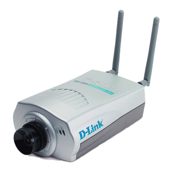
Package Contents Contents of Package: One Internet Camera Two External Wireless Antennas (Wireless Internet Camera only) One Installation CD-ROM One AC power adapter One Camera Stand One Category 5 Ethernet Cable If any of the above items are missing, please contact your reseller. System Requirements: Local Area Network: 10Base-T Ethernet or 100Base TX Fast Ethernet Wireless Local Area Network: IEEE 802.11b Wireless LAN (Wireless Internet... -
Page 4: Introduction
System Requirements (continued): IPView Configuration Windows XP, Me, 2000, 98SSe or 98 CPU: Pentium II, 350 MHz or above Memory Size: 128 MB (256 MB recommended) VGA card resolution: 800x600 or above Introduction The Internet Camera connects directly to an Ethernet, Fast Ethernet, or 802.11b (DCS- 1000W only) Network. -
Page 5: Wired And Wireless Network Support
Wired and Wireless Network Support The Internet Camera supports both wired and wireless transmission (DCS-1000W only, the DCS-1000 supports wired transmittion only) providing the advantage of mobility, flexibility and high-speed of wireless LAN based technology, IEEE 802.11b, to transform the Internet Camera into a total solution for your network. There are three modes available,... -
Page 6: Reset Button
Connections Antenna Connectors (DCS-1000W only) Ethernet Cable Connector Reset Button Network Cable Connector The Internet Camera’s rear panel features an RJ-45 connector for connections to 10Base- T Ethernet cabling or 100Base-TX Fast Ethernet cabling (which should be Category 5 twisted-pair cable). The port supports the NWay protocol, allowing the Internet Camera to automatically detect or negotiate the transmission speed of the network. -
Page 7: Bottom Panel
Connections (continued) Slide Switch (DCS-1000W only) The slide switch permit user’s to determine the type of network communication media for the Internet Camera and is positioned on the rear panel. The three settings are as follows: LAN (Local Area Network Only) LAN/WLAN (Local Area Network and Wireless Local Area Network. -
Page 8: Power Led
LEDS stands for Light-Emitting Diode. Power LED The Power LED is positioned on the right side of the Internet Camera lens while facing the Internet Camera. Steady blue confirms that the Internet Camera is powered on. Note: There are three settings for the Power LED to control the light illumination for monitoring purposes: Normal / Off / Dummy. -
Page 9: Hardware Installation
Hardware Installation 1. Attach Wireless Antenna (Wireless Internet Camera only) From the rear panel of the Internet Camera, screw the 2 external antennas that came with DCS-1000W into the antenna connector. 2. Configure Network Communication (Wireless Internet Camera only) From the rear panel of the Internet Camera select the desired network communication for the Internet Camera from the Slide Switch. -
Page 10: Security
Connecting the Internet Camera to the Camera Stand The Internet Camera comes with a camera stand with a swivel ball screw head that can be attached to the Internet Camera bottom bracket cavity. Attach the camera stand to the Internet Camera and station it for your application. -
Page 11: Using The Internet Camera As A Security System
Cameras. Passive components must not exceed 5V 100mA. Active components must be self-powered by an external power source. For the demonstration below a D-Link DCS-1000 was purchased from www.dlinkshop.com , the security equipment was purchased from www.smarthome.com, and some cable accessories from a local hardware store. - Page 12 Basic Hardware Set-up Diagram The diagram below shows the hardware configuration for 1 Active Sensor (PIR Motion Sensor), 1 Passive Sensor (Magnetic Switch), and 1 output (For Relay) for a siren. Passive Component Notes!!! Only simple magnetic or contact switches can be used for Passive components. This limitation is by the camera only supplying 5V and less then 100mA current to those circuits.
-
Page 13: Camera Configuration
Camera Configuration Follow the instructions for setting up your wired or wireless camera. If the camera is for home use and is behind an Internet router, additional set-up notes for your router can be found on www.dlink.com. Once logged into the camera on the main menu click/select trigger and the following screen will appear. - Page 14 Additional Component Listing for Use with the Internet Camera All components listed below can be found at www.smarthome.com Passive Components Glass Break Sensor PN: 5150w - Sentrol Inc. Any contact switch or pressure switch not exceeding 100mW current draw. Examples @ http://www.smarthome.com/ seccontacts.html Active Components Coral Plus Temperature Compensated PIR Detector - Visonic Ltd.Duet Dual Microwave/...
-
Page 15: Software Installation
(i.e. PC=192.168.0.5, Camera=192.168.0.20) for the two devices to communicate. For instructions on how to do this, please access instructions for installing any of the D-Link Broadband Gateway products from support.dlink.com/products. The DI-713 or DI-714 are good products to use as an example as their Quick Install Guides are the most up- to-date. -
Page 16: System Administration
System Administration Click on “System Administration” from the Home screen to access the settings required for the Internet Camera. There will be several options in the System menu bar to choose from to set your Internet Camera and they are as follows: System Image Users... - Page 17 System Administration System Administration – System The System menu contains commands for settings that are required for inputting key details to set-up the Internet Camera for operation. Click on System in the system administration menu bar and the System screen will appear as illustrated below:...
-
Page 18: Camera Name
Camera Name: This field is used for entering a descriptive name for the device. The default setting for the Camera Name is CS-xxxxxx, where xxxxxx is the last six digit of the MAC Address. The maximum length is 32 (Printable ASCII). Location: This field is used for entering a descriptive name for the location used by the Internet Camera. - Page 19 The default settings are as follows: Default IP – 192.168.0.20 Subnet Mask – 255.255.255.0 Default Gateway – 0.0.0.0 Assign Automatically Using It is recommended that you do not use an Automatically Assigned IP address as it may be difficult to determine the IP address of the unit after the IP address has been asssigned.
- Page 20 Network Name: (for Wireless Internet Camera only) This field is used to setup which wireless network (ESS-ID Extended Service Set ID) DCS-1000W is to be connected for communication. The ESS-ID is a unique identifier shared among all points in a wireless network environment. The default Network Name is a blank space (NULL String);...
- Page 21 Encryption WEP Key: (for Wireless Internet Camera only) Wireless network communications are easily intercepted. WEP (Wired Equivalent Privacy) is an encryption method specified by the IEEE 802.11b standard to make any intercepted communications extremely difficult to interpret by unauthorized parties. To enable WEP Encryption, first decide which WEP key format will be applied.
-
Page 22: Led Control
The default setting for the Encryption Key is Disable. Therefore, to secure the wireless transmission be sure to Enable the Encryption Key by entering the relevant data. Note: Carefully input the Encryption Code, any error setting the code will cause the communication link to fail. - Page 23 Instructions for installing ActiveX from the driver CD is included in this manual. Refer to the section labeled Software Installation. Open a second port: The Web Server field allows settings to open a second port for the Internet Camera. This will permit users IP Sharing Gateways to support multiple Internet Cameras.
- Page 24 Video Resolution: Select the desired video resolution format ranging from 160x112, 320x240 (default) or 640x480 Compression Rate: Select the desired compression rate from five levels from very low to very high. Higher video compression rates will generate more compact file sizes with less video quality, and lower video compression will result in larger files with higher video quality.
- Page 25 Light Frequency: Adjust the light frequency to suit your area of operation. The options are either 50 Hz or 60 Hz (default). 50 Hz and 60 Hz variants are available to accommodate the different light frequencies found in USA (60 Hz) and Europe (50 Hz) to ensure better image quality.
- Page 26 User Password: Enter the user’s password you want to assign to the specific user-name. The maximum password length is 8 characters (Printable ASCII). I/O Output Control: The Administrator has the authority to give permission to control the I/O Output Control to users by selecting Yes or No to activate the I/O Output control. To add a new user name, input the necessary information first and click on Add.
- Page 27 Click on DateTime in the system administration menu bar and the DateTime screen will appear as illustrated below: DateTime: Select Synchronized with Time Server and the time will be based on the GMT setting. The time will be synchronized every 10 minutes. This is also the default setting for the Internet Camera.
- Page 28 Note: Please find below the NTP server web addresses, for your reference, to set the time server. http://www.eecis.udel.edu/~mills/ntp/clock1.htm http://www.eecis.udel.edu/~mills/ntp/clock2.htm Save/Cancel: After making sure all settings in the System are correct, click on the Save icon to store the settings in the Internet Camera. You can alternatively click on the Cancel icon to restore all settings to the values last saved to or retrieved from the Internet Camera.
- Page 29 The default setting for the I/O Trigger functions is “disabled.” You must enable the I/O Trigger first before the Triggers will perform. There are two options to select from the Trigger screen I/O Input 1 Trigger and I/O Input 2 Trigger. I/O Input 1 Trigger: Select “Send e-mail attached with image”...
- Page 30 System Administration - Upload The Upload menu contains commands for FTP server, time schedule and manual operation settings. Click on Upload in the system administration menu bar and the Upload screen will appear as illustrated below: There are three options to select from the Upload screen: FTP Server, Time Schedule and Manual Operation.
- Page 31 • User Name: Enter the user name in this field. • Password: Enter the user password in this field to login the FTP server. • Directory Path: It is recommended to leave this field blank. By default, the path will be the ftp root directory. Optional: Enter an existing folder name in this field, and the images will be uploaded to the given folder in the ftp root directory.
- Page 32 System Administration - Information The Information menu contains commands for displaying information about the Internet Camera. Click on “Information” in the system administration menu bar and the Information screen will appear as illustrated below: The Information table provides detailed information about the Internet Camera such as the Model Name, Firmware Version, Mac Address, and IP Address.
-
Page 33: Factory Reset
Factory Reset: A factory reset restarts the Internet Camera and returns all of its settings to their default values. The Factory Reset panel contains the message “Do you really want to factory reset this device?” and a YES button. If you do not want to carry out a factory reset command, exit the panel without clicking YES, otherwise click on the “YES”... -
Page 34: View Image – Java Mode
Note: Please refer to the appendix to learn how to install ActiveX. 1. Install to the Web Server 2. Install to your Local PC In the View Image – ActiveX Mode you are allowed two output trigger options and one image upload option. Just click on the desired selection “ON” or “OFF”... -
Page 35: Ipview Application Installation
Camera Name* - The Camera name will be display when the Camera Name field is entered in the Web Configuration setting under “System” Location** - The location of the Internet Camera will be displayed when the Location field is entered in the Web Configuration settings under “System.” Date/Time*** - The date/time of the Internet Camera will show the date and time which comes either from the time server or from manual settings. - Page 36 Once executed a prompt will appear requesting the input of the desired language selection. Make the desired selection and click on OK to continue. The Welcome screen will appear. Click on the Next button to proceed with the installation.
- Page 37 The License Agreement prompt will appear as below. Read the details carefully and click on the Yes icon to continue with the installation procedure.
- Page 38 The Select Program Folder prompt will appear providing information on where the IPView application is located, click on Next to continue. If you wish to modify your settings, click on Back to return to the previous screens. Please wait until one of the two dialog boxes appear, select “Yes, I want to restart my computer now”...
- Page 39 or click on Finish to complete the installation procedure After successfully installing the IPView, the application program for the Internet Camera is automatically installed to \Programs\Files Directory. To start running the IPView click on windows Start > Menu > Programs > IPView >IPView Once IPView is executed a Login prompt will appear, you must enter the default User Name: admin into the respective field and click on “OK”...
- Page 40 Once logged in, the IPView application is executed and the IPView interface will appear as follows in the default List View format:...
-
Page 41: Ipview - Getting Started
IPView - Getting Started This section describes the operation of the IPView application user interface with detailed procedures for using the application. IPView PView is responsible for the management of preview, configuration, and searching for each camera. It is designed with a user-friendly interface for ease of control and navigation as illustrated below. -
Page 42: How To Change The Password
How to Change the Password Change Password When IPView is used for the first time it is highly recommended to change the User Name and Password by the Administrator to constrain users access to the IPView application. Once the User Name and Password are defined only the Administrator has access to the management of IPView applications. -
Page 43: How To Add A Camera
Enter a User Name, then enter the Password twice. Once all the new details are entered click OK. Make sure to save any changes you have made to keep the information updated. Note: Alternatively you can click the Options icon as illustrated or use the hot key F10. - Page 44 If you are unsure of the IP Address of the camera you can click on Browse, the Browse Camera dialog box will appear with a blank screen as illustrated below. Click on Search. IPView will detect and search all the available cameras that are installed on the local area network as depicted below: Highlight the camera you wish to add and click on Add.
- Page 45 Alternatively, you can double-click on the camera you wish to add and the Add Camera dialog box will appear once again with the IP Address entered. Click on Add, and the camera will be automatically added into the IPView list view format.
-
Page 46: How To Delete A Camera
Make sure to save any changes you have made. Note 1: You are only able to add one camera at a time. Note 2: Alternatively you can click the Add icon as illustrated, or use the hot key Shift+Ins. How to Delete a Camera Delete Camera To delete a camera you must highlight the camera you wish to delete from IPView list view format. -
Page 47: How To Change The Ip Address
How to Change the IP Address Change the IP Address To change an IP Address for a camera, you must first locate the camera by first selecting Camera > Add. An Add Camera dialog box will appear as illustrated below. Click on Browse, the Browse Camera dialog box will appear with a blank screen as illustrated below. - Page 48 Click Search. IPView will detect and search all the available cameras that are installed on the local area network as depicted below: Highlight the camera you wish to change and click Change IP. The Change IP Address dialog box will appear as depicted below: Enter the new IP Address, the Subnet Mask and the Default gateway into the respective fields and click OK.
-
Page 49: How To Format The Camera View
How to Format the Camera View View Camera From the menu bar select View > 4 Cameras (other choices are available in 1 Camera, 9 Cameras and 16 Cameras viewing format). The viewing screen will appear with the video image. Note: The icon on the upper left corner of the screen will appear with the camera number that is being displayed... -
Page 50: Rotate Video
Rotate Video In View Mode format, click on the icon located on the upper left corner of the screen and a pop-up menu will appear as shown below. Once you click Rotate Right or Rotate Left in the menu, the video will rotate 90 degrees to the right or left. -
Page 51: How To Start Recording
Alternatively, select from the viewing mode either 1, 4, 9, or 16 cameras. Click on the icon located on the upper left corner of the screen. A case sensitive menu will appear. Select the Snap shot icon. A Save Image dialog box will appear for you to save the snap shot picture. -
Page 52: How To Adjust The Property Setting
How to Adjust the Property Setting Property is initiated by selecting Camera > Property. A dialog box will appear which allows for Web Configuration settings and upgrading firmware. (Please refer to the appendix for detailed information.) The Camera Property dialog box will appear. - Page 53 IP Assignment There are two options: Manually Assign or Assign Automatically Using. (Please refer to the Web Configuration section: System Administration – System for further details.)
- Page 54 DNS (Domain Name System) server is an Internet service that translates domain names into IP addresses. Enter at least one DNS IP Address. Please refer to the Web Configuration section under System Administration – System for further details.
- Page 55 Wireless - (For Wireless Internet Camera only) Allows for the settings for Connection mode, Network name, Wireless Channel and WEP key. Please see the Web Configuration section under System Administration-System for further details.
- Page 56 Misc Allows setting for LED Control, ActiveX control location, and second port. (Please refer to the Web Configuration section under System Administration – System for further details.) Image Provides the settings for the video image of the camera such as brightness, contrast, hue, resolution, compression, frame rate, and light freq.
- Page 57 Users Allows the system administrator to allow or deny users permission to monitor the camera from a remote site by using Add or Delete user. To add a user click on the Add icon and the Add User dialog box will appear. Enter the User Name and Password into the specific field.
- Page 58 Date/Time Set the camera’s time and date to provide correct time information to users who might be thousands of miles away in a remote site by selecting Synchronized with Time Server or Set Manually. (Please refer to the Web Configuration section under System Administration – TimeDate for further details.) Trigger 1 Contains commands for setting the Input/Output Trigger connectors providing...
- Page 59 Trigger 2 Contains commands for setting the Input/Output Trigger connectors that provide the physical interface for 1 digital output and 1 digital input, used for connecting a diversity of external alarm devices to the camera such as IR- Sensor and alarm relay. (Please refer to the Web Configuration section under System Administration –...
- Page 60 Tools Contains commands to reset the camera and update firmware (please refer to the appendix for detailed information). Please refer to the Web Configuration section under System Administration – Tools for further details on reset.
- Page 61 Recording The software will create a camera name folder in the File Path specified and record the video images with file name by date and time. You can adjust the maximum file size by clicking on By Size from the Recording Options field. (The default size is 50MB.) If the recorded video files reach the file size allocated, video images will be recorded into another file automatically.
- Page 62 Schedule Allows customized settings to start recording specified by date or by week. Check the Recording Schedule box to enable this option. Select By Date and enter in the dates, Stop, and Start Times. The camera will start to record according to the specified date and time period entered.
- Page 63 Motion Detection (List View) In the list view for the camera, a red circle preceeding the camera name indicates that the camera detected motion and is recording. The Camera will continue to record for 10 seconds after it has stopped detecting motion, then will stop recording.
-
Page 64: Menu Bar
Menu Bar The menu bar provides easier access for users to navigate the IPView with different selections along with hot key capabilities as follows: Menu Bar - File File on the menu bar contains New, Open, Save, Save As and Exit for users to create new files, open existing files, save files, and exit the IPView as depicted below. -
Page 65: Menu Bar – View
Menu Bar – View View on the menu bar provides users with management capabilities for Columns, List, Camera and Refresh. You can view the Camera in 1 Camera, 4 Cameras, 9 Cameras, or 16 Cameras mode. The View menu bar is pictured below. Columns When Columns is launched, a dialog box will appear displaying the Column Settings. -
Page 66: List View
List View All the cameras and their properties, such as the camera name, IP address, user name, and location, will be displayed in the list view. Note: Right click on any camera to bring up a context sensitive menu of actions you can apply to the selected camera. -
Page 67: Menu Bar - Camera
Menu Bar - Camera Camera on the menu bar provides options to manage the camera. Add up to 16 additional Cameras for viewing. The Camera menu also allows you to Delete a camera, manage the Property, Enable real timevideo capture, take a Snap shot image, and Enable Motion for Motion Detection. -
Page 68: Menu Bar - Help
Account Allows you to change your log in name and password. Overwrite Allows old video files to be overwritten and replaced by new recorded files. Choose Overwrite (Time) to have video clips recorded in the time frame specified overwritten with new recorded files. Choose Overwrite (Space) to overwrite old files with new recorded files once the disk drive reaches the specified drive space. -
Page 69: Ipview Icon Description
IPView Icon Description Open a new file. The hot key is Ctrl+N. Open an existing file. The hot key is Ctrl+O. Save a file. The hot key is Ctrl+S. List view format. The hot key is Ctrl+F1. 1 Camera view format. The hot key is Ctrl+F3. 4 Camera view format. -
Page 70: Context Sensitive Menu
Context Sensitive Menu In List View format, highlight a camera and right-click to bring up a context sensitive menu for features such as Add, Delete, Property, Enable, and Snap shot, Enable Motion, and Start/Stop recordings. In View mode format click on the icon located on the upper left corner of the screen and a case sensitive menu will appear as illustrated below. -
Page 71: Uninstall Ipview Application
Uninstall IPView Application Click on windows Start Menu / Programs / IPView / Uninstall IPView. A new prompt screen will be displayed like the one below confirming the removal. Choose the option that you want and click Next to continue the process or click on Cancel to reject the uninstall process. - Page 72 The InstallShield Wizard prompt will appear. Click Finish to complete the uninstallation procedure.
-
Page 73: Appendix
Appendix Frequently Asked Questions Internet Camera Features Q: What is an Internet Camera? A:The Internet Camera is a standalone system connecting directly to an Ethernet or Fast Ethernet network and supported by the wireless transmission based on the IEEE 802.11b standard. It is different from the conventional PC Camera, the Internet Camera is an all-in-one system with built-in CPU and web-based solutions providing a low cost solution that can transmit high quality video images for monitoring. -
Page 74: Troubleshooting
Q: Can the Internet Camera be setup as a PC-cam on the computer? A: No, the Internet Camera is used only on Ethernet and Fast Ethernet network and supported by wireless transmission. The D-Link DSB-C100, DSB-C300, DSC-350 or DSC-350F can be used as a PC Camera (Webcam). - Page 75 need to first disconnect the Internet Camera from the network. Then run the PING utility (follow the instructions in Appendix B - PING Your IP Address.) A2: Another possible reason is the IP Address is located on a different subnet. To fix the problem, run the PING utility (follow the instructions in Appendix B - PING Your IP Address).
- Page 76 A3: The wireless connection might be at fault. In ad-hoc mode make sure the Internet Camera wireless channel and ESS-ID is set to match the PC/Notebook wireless channel and ESS-ID for direct communication. Since The Internet Camera ad-hoc mode supports two modes (802.11 ad-hoc mode and proprietary ad-hoc mode), make sure that you are using the same mode on each device.
-
Page 77: How To Ping Your Ip Address
A2: There might be wireless transmission interference. Make sure there are no other wireless devices on the network that will affect the wireless transmission. Q: The images is of poor quality, how can I improve the image quality? A1: Make sure that your computers display properties are set to at least 15- bit color. - Page 78 I/O Connector I/O Connector Definition for the Internet Camera An 8-pole connector is provided for auxiliary I/O connections to the Internet Camera. The I/O connector provides the physical interface for 2 digital outputs and 2 digital inputs that are used for connecting a diversity of external alarm devices to the Internet Camera such as IR-Sensor and alarm relay.
- Page 79 I/O Schematic Diagram voltage 5V. voltage 5V. 1. When connecting a device to the Input connector, the device must be a passive component without voltage and electrical current. 2. When connecting other devices through the Output connector, please make sure the maximum current of DC 5V, 100mA is strictly observed. 3.
-
Page 80: Upgrade Firmware
Upgrade Firmware You can update the firmware from the IPView application. With IPView running, select Camera > Properties and the Camera Property dialog box will appear. Select the Tools tab and enter the full path of the firmware binary file name in the Update Firmware field or you can click on the Browse button to select the file. -
Page 81: Time Zone Table
Time Zone Table GMT stands for Greenwich Mean Time, which is the global time that all time zones are measured from. -
Page 83: Xplug Control Installation
Xplug Control Installation Installation to a Web Server Important Information It is highly recommended to install the Xplug Control application to the Web Server for IE 5.0. It must be installed to a Public Domain with a Fixed IP address. 1. -
Page 84: Installation To A Local Pc
Installation to a Local PC Insert the CD-ROM into the CD-ROM drive to initiate the auto-run program. Once completed a menu screen will appear as follows: To install Xplug Control click on the “Xplug Control” button to activate the installation procedure for the plug-in program. Once executed a prompt will appear requesting the input of the desired language selection. - Page 85 The Welcome screen will appear. Click Next to proceed with the installation. The License Agreement prompt will appear as below. Read the details carefully and click Yes to continue with the installation procedure.
-
Page 86: Adjusting The Cameras Focus
Click Finish to complete Setup of the Xplug Control Utility program for the Internet Camera. Adjusting the Cameras Focus The Internet Camera features an exchangeable C/CS-type lens that can be used for different applications as necessary. It supports rotational focus control so the lens can be adjusted to focus under normal and stable conditions to maximize the image quality of the Internet Camera. - Page 87 Camera Lens Adjust by turning clockwise or counter-clockwise Note: You can further adjust the Internet Camera’s image quality through the Web Configuration under System Administration - Image. Please refer to Web Configuration section for further details. Warning Direct exposure to sunlight may cause permanent damage to the CMOS sensor.
-
Page 88: Replacing The Lens
Replacing the Lens Since the Internet Camera is designed with a CS- mount, the lens equipped with the Internet Camera can be replaced with any standard C or CS lens commonly used within the surveillance industry. Follow the instructions below to replace the supplied lens with any C or CS type lens. -
Page 89: Technical Specifications
Technical Specifications Video specification Resolution: Sensor: Gain control: Exposure: White Balance: Shutter: Minimum Illumination: Focal Length: Aperture: Focus Extent: Lens mounting: Image (Video Setting) Image compression: Frame rate: Compression Rate selection: 5 level (Very Low, Low, Medium, High, Very Frame rate setting: Video resolution: Brightness control: Contrast control:... -
Page 90: Operating Environment
LED Indicator: Power LED (Blue) LAN/WLAN Activity LED (Orange) Note: LED three mode setting can be changed by software. (Normal / Off / Dummy) Power Supply: Power Communication: Slide Switch: Antenna Connector: Communication Support Communication: Encryption: Communication protocol: Web Configuration Requirements: •... -
Page 91: Contacting Technical Support
Contacting Technical Support You can find the most recent software and user documentation on the D-Link website. D-Link provides free technical support for customers within the United States for the duration of the warranty period on this product. U.S. customers can contact D-Link technical support through our web site, or by phone. -
Page 92: Warranty And Registration
D-Link’s sole obligation shall be to repair or replace the defective Hardware during the Warranty Period at no charge to the original owner or to refund at D-Link’s sole discretion. Such repair or replacement will be rendered by D-Link at an Authorized D-Link Service Office. The replacement Hardware need not be new or have an identical make, model or part. - Page 93 D-Link may reject or return any product that is not packaged and shipped in strict compliance with the foregoing requirements, or for which an RMA number is not visible from the outside of the package. The product owner agrees to pay D-Link’s reasonable handling and return shipping charges for any product...
- Page 94 FROM THE USE OF THE PRODUCT, RELATING TO WARRANTY SERVICE, OR ARISING OUT OF ANY BREACH OF THIS LIMITED WARRANTY, EVEN IF D-LINK HAS BEEN ADVISED OF THE POSSIBILITY OF SUCH DAMAGES. THE SOLE REMEDY FOR A BREACH OF THE FOREGOING LIMITED WARRANTY IS REPAIR, REPLACEMENT OR REFUND OF THE DEFECTIVE OR NON-CONFORMING PRODUCT.
-
Page 95: Index
Index Add a Camera 45 Adjust the Property Setting 52 Adjusting the Cameras Focus 83 Antenna Connector 7 ASCII input format: (for Wireless Internet Camera 21 Assign Automatically Using 19 Bracket Cavity 7 Broad Range of Applications 5 Change Password 42 Change the IP Address 43 Columns 63 Connecting the DCS-1000W to the Camera Stand 10... - Page 96 HEX input format 21 HEX input format: (for Wireless Internet Camera on 21 How to Add a Camera 45 How to Adjust the Property Setting 51 How to Change the Password 42 How to Change the IP Address 43 How to Delete a Camera 48 How to format the Camera view 49 How to PING Your IP Address 74 How to take a Snap-Shot with the Camera 50...
- Page 97 Recording 61 Remote Monitoring Utility 5 Replacing the Lens 85 Reset Button 6 Rotate Video 50 Slide Switch 7 Start Recording 51 Stop Recording 51 System Administration 16 System Requirements 3 Time Zone Table 78 Trouble Shooting 71 Troubleshooting 71 Upgrade Firmware 77 Upload 30 Video specification 86...