J+J J4C Series Handbook
Hide thumbs
Also See for J4C Series:
- Installation instructions (2 pages) ,
- Installation instruction (30 pages)
Advertisement
Quick Links
Advertisement

Related Manuals for J+J J4C Series


Summary of Contents for J+J J4C Series
- Page 1 HANDBOOK www.jjbcn.com Handbook (EN) 2402V2...
- Page 2 • S20, S35, S55, S85, B20, B35, B55, B85 • Bluetooth ............69 • S140, S300, B140, B300 • Modbus ............70 › 03. J4C series ............. 9 › 06. Kits ..............71 • Voltage ............10 • DPS ............... 72 •...
- Page 3 01 INTRODUCTION Index...
- Page 4 HANDBOOK AUTOMATE YOUR VALVES WITH JJ PRODUCTS A new feature of this range is a motor with Brushless technology, which is more efficient and therefore longer-lasting. It is marketed in the format J4C S for the multi-voltage range spanning from 24-240 VDC / VAC and in format J4C B for 12 VDC / VAC. It also includes the possibility of incorporating all the options, such as our DPS (Digital Positioner System) and BSR (Battery System Return) kits, which have been designed for this series.
- Page 5 HANDBOOK OPTIONS BLUETOOTH MODBUS INTERFACE We have introduced the Bluetooth Modbus System Digital Positioner System Battery System Returns Interface System communication system in our actuators, in order to • Plug and play Digital positioner for our J4C BSR system for our J4C models. Using the Interface KIT cable we communicate with our actuators, models.
-
Page 6: Part List
02 ACTUATOR PART LIST Index... - Page 7 HANDBOOK / ACTUATOR PART LIST ACTUATOR PART LIST MODELS: S20, S35, S55, S85, B20, B35, B55, B85 Manual override Position indicator Visual control of operation Power supply plug Volt free contact plug Automatic/ ISO multiflange manual lever Index...
- Page 8 HANDBOOK / ACTUATOR PART LIST ACTUATOR PART LIST MODELS: S140, S300, B140, B300 Manual override Position indicator Visual control of operation Power supply plug Volt free contact plug Automatic/ manual lever ISO multiflange Index...
- Page 9 03 J4C SERIES DETAILS Index...
-
Page 10: Electrical Connectors
HANDBOOK / J4C SERIES Read these instructions before connecting the actuator. Damage caused by non compliance of these instructions is not covered by our warranty. J4C Electric actuators operate with the use of live electricity. It is recommended that only qualified electrical engineers be allowed to connect or adjust these actuators. - Page 11 J.J. BCN INTERNACIONAL S.A. NEWS! ELECTROSTATIC DISCHARGE IMMUNITY (ESD) This enhancement aims to provide immunity to electrostatic discharge (ESD) according to the IEC EN 61000-4-2 Standard, ensuring higher performance and durability of the actuator. Once the electrical connections have been completed, make sure that the plug completely covers the screws to guarantee ESD protection.
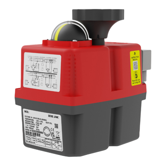
- Page 12 HANDBOOK / J4C SERIES ID ACTUATOR LABEL Actuator Model. Duty: 75%. Example: S20 Model - Maneuver time = 10 sec. Voltage to be connected. Time between maneuvers = 3.3 sec. Actuator ready to bear between -20ºC / +70ºC. QR code for manufacturing.
- Page 13 HANDBOOK / J4C SERIES LOCAL VISUAL POSITION INDICATOR All J4C actuators are supplied with a local visual position indicator comprises a black base with a yellow insert that shows, both the position and direction of rotation (Fig.6). The open and close positions have the following logos molded into the top cover OPEN 90 and CLOSE 0.
- Page 14 HANDBOOK / J4C SERIES EMERGENCY MANUAL OVERRIDE FACILITY The J4C has 2 operating modes, automatic and manual, the required mode is selected by using a lever on the lower half of the actuator housing (Fig 7). The 2 positions are marked: •...
- Page 15 HANDBOOK / J4C SERIES When “MAN” function is selected: The electronic system cuts the power to the motor after a few minutes. The mechanical connection between the motor and the output shaft is disconnected. The desired position can be achieved by using the hand wheel.
- Page 16 HANDBOOK / J4C SERIES POSITION OF THE CAMS Cams 1 and 3 Cams 2 and 4 Cam 1 is to adjust the close position. Cam 2 is to adjust the open position. Cam 3 is to adjust the close position confirmation.
- Page 17 HANDBOOK / J4C SERIES To adjust the close position at less than 0º. Cams 1 and 3 Turn the wrench to clockwise direction - cams 1 and 3. The cam 3 (confirmation) should press the lever of the micro switch a bit earlier than the cam 1.
- Page 18 HANDBOOK / J4C SERIES TABLE OF CONSUMPTIONS - ON-OFF ACTUATOR J4C 20 consumption Unload Max. Operational Torque 20 Nm Max. Torque Break 25 Nm Volatge Model 12 VDC 0,75 9,06 1,80 21,60 1,95 23,36 24 VDC 0,45 10,77 0,90 21,49...
- Page 19 HANDBOOK / J4C SERIES TABLE OF CONSUMPTIONS - ON-OFF ACTUATOR J4C 85 consumption Unload Max. Operational Torque 85 Nm Max. Torque Break 90 Nm Volatge Model 12 VDC 0,62 7,42 2,11 25,34 2,28 27,32 24 VDC 0,36 8,55 1,08 25,87...
- Page 20 HANDBOOK / J4C SERIES TABLE OF CONSUMPTIONS - DPS ACTUATOR J4C 20 consumption Unload Max. Operational Torque 20 Nm Max. Torque Break 25 Nm Volatge Model 12 VDC 0,84 10,08 2,02 24,19 2,18 26,21 24 VDC 0,50 12,10 1,01 24,19...
- Page 21 HANDBOOK / J4C SERIES TABLE OF CONSUMPTIONS - DPS ACTUATOR J4C 85 consumption Unload Max. Operational Torque 85 Nm Max. Torque Break 85 Nm Volatge Model 12 VDC 0,69 8,33 2,36 28,36 2,55 30,64 24 VDC 0,40 9,68 1,21 29,03...
- Page 22 HANDBOOK / J4C SERIES EXTERNAL CONNECTING DIAGRAM (STANDARD) ON - OFF VAC The power supply is connected to the grey “A” DIN plug. Neutral PIN 1 + Phase PIN 2 = Close actuator. Neutral PIN 1 + Phase PIN 3= Open actuator.
- Page 23 HANDBOOK / J4C SERIES EXTERNAL CONNECTING DIAGRAM (OPTIONAL) STANDARD MODE · 3 WIRES ON - OFF = Power supply plug A: VAC 3 WIRES (Grey plug) PIN 1 = Neutral + PIN 2 = Phase = Close PIN 1 = Neutral + PIN 3 = Phase = Open...
- Page 24 HANDBOOK / J4C SERIES 4 MODE ON - OFF = Power supply plug A: VAC 3 WIRES (Grey plug) PIN 1 = Neutral + PIN 2 = Phase = Stop PIN 1 = Neutral + PIN 3 = Phase = Open...
- Page 25 HANDBOOK / J4C SERIES ACTUATOR OPERATIONAL STATUS MODELS: 20, 35, 55, 85, 140, 300 The LED Light provides visual communication between the actuator and the user. The current operational status is shown by different LED colors. ON-OFF ACTUATOR ACTUATOR OPERATIONAL STATUS...
- Page 26 HANDBOOK / J4C SERIES ACTUATOR WITH BSR ACTUATOR OPERATIONAL STATUS Without power supply In open position In close position Opening Closing Torque limiter function on, moving from close to open Torque limiter function on, moving from open to close Actuator in MANUAL mode (Exceeded time)
-
Page 27: Data Sheet
04 DATASHEET Index... -
Page 28: General Characteristics
HANDBOOK / DATASHEET J4C 20 J4C 20 - GENERAL CHARACTERISTICS Technical Data Operation time unload 9 Sec. /90º Maximum torque break 25 Nm / 221 lb/in Maximum operational torque 20 Nm / 177 lb/in Duty rating Max. Working angle 0º to 270º Electronic Data Limit switch 4 SPST NO micro (2 motor stop and 2 confirmations) - Page 29 HANDBOOK / DATASHEET J4C 20 J4C 20 SIZES Index...
- Page 30 HANDBOOK / DATASHEET J4C 20 EXPOLDED VIEW J4C 20 CODE QUANTITY CODE QUANTITY CODE QUANTITY +AP00069 AP00345 AP00042 1(*09) MM01382 MM00187 AP00372 +AP00013 AP00346 AP00456 +AP01042 AP00053 MM00056 +AP00084 AP00133 AP00054 AP00340* MM00258 AP00457 AP00023 AP00541 MM01474 AP00037 AP00455 MM01475 AP00083 AP00050 AP01099...
- Page 31 HANDBOOK / DATASHEET J4C 20 EXPOLDED VIEW J4C 20 CODE QUANTITY CODE QUANTITY CODE QUANTITY AP00533 1 (S TYPE) AP01056 MM01210 AP01059 1 (B TYPE) AP00926 AP01000 AP00080 AP00070 AP00161 AP01047 AP01066 AP00048 AP01045 AP01015 MM01324 AP00159 AP01017 AP00376 AP00911 MM01211 AP00879 Index...
- Page 32 HANDBOOK / DATASHEET J4C 20 EXPOLDED VIEW J4C 20 CODE QUANTITY CODE QUANTITY AP00974 AP00057 AP00032 AP00794 AP00021 AP00991 AP00960 AP01013 AP00143 AP01000 AP00955 AP00343 AP00861 AP00031 AP00145 AP00014 AP00251 Index...
- Page 33 HANDBOOK / DATASHEET J4C 35 J4C 35 - GENERAL CHARACTERISTICS Technical Data Operation time unload 9 Sec. /90º Maximum torque break 38 Nm / 359,3 lb/in Maximum operational torque 35 Nm / 309 lb/in Duty rating Max. Working angle 0º to 270º Electronic Data Limit switch 4 SPST NO micro (2 motor stop and 2 confirmations)
- Page 34 HANDBOOK / DATASHEET J4C 35 J4C 35 SIZES Index...
- Page 35 HANDBOOK / DATASHEET J4C 35 EXPOLDED VIEW J4C 35 CODE QUANTITY CODE QUANTITY CODE QUANTITY AP00455 AP00457 AP00162 AP00050 MM01474 AP00083 MM01475 AP00044 1(*14) AP00053 AP00043 1(*11) AP01099 AP00037 AP00042 1(*09) AP01098 AP00345 MM00187 MM00004 AP00372 MM00005 AP00456 AP00346 AP00133 AP00056 AP01138 AP00054...
- Page 36 HANDBOOK / DATASHEET J4C 35 EXPOLDED VIEW J4C 35 CODE QUANTITY CODE QUANTITY AP00794 AP00021 AP01013 AP00960 AP00991 AP00143 AP01000 AP00032 AP00031 AP00955 AP00343 AP00861 AP00014 AP00974 AP00251 AP00145 Index...
- Page 37 HANDBOOK / DATASHEET J4C 35 EXPOLDED VIEW J4C 35 CODE QUANTITY CODE QUANTITY CODE QUANTITY AP00159 AP00070 MM01324 AP00376 AP01028 AP00080 AP00161 AP00048 AP01066 MM01211 AP00057 AP01045 MM01210 AP00911 AP01047 AP01000 AP00879 AP00533 1 (S TYPE) AP01023 AP01056 AP01059 1 (B TYPE) AP01017 AP00926 Index...
- Page 38 HANDBOOK / DATASHEET J4C 55 J4C 55 - GENERAL CHARACTERISTICS Technical Data Operation time unload 13 Sec. /90º Maximum torque break 60 Nm / 530 lb/in Maximum operational torque 55 Nm / 486 lb/in Duty rating Max. Working angle 0º to 270º Electronic Data Limit switch 4 SPST NO micro (2 motor stop and 2 confirmations)
- Page 39 HANDBOOK / DATASHEET J4C 55 J4C 55 SIZES Index...
- Page 40 HANDBOOK / DATASHEET J4C 55 EXPOLDED VIEW J4C 55 CODE QUANTITY CODE QUANTITY CODE QUANTITY AP00083 MM01474 AP00049 AP00053 AP00046 1 (*17) MM01475 AP00037 AP00150 1 (*11) AP01099 AP00345 MM00004 AP00045 1 (*14) AP00372 MM00140 +AP00069 AP00346 AP00016 MM01382 AP00133 +AP00013 AP00110 MM00258...
- Page 41 HANDBOOK / DATASHEET J4C 55 EXPOLDED VIEW J4C 55 CODE QUANTITY CODE QUANTITY AP01059 1(B TYPE) AP01000 AP00533 1(S TYPE) AP00059 AP01047 AP00492 AP00080 AP00291 AP00911 AP01045 AP00377 AP00079 AP01056 AP00159 AP00161 AP00926 AP01066 MM01211 MM01210 MM01324 Index...
- Page 42 HANDBOOK / DATASHEET J4C 55 EXPOLDED VIEW J4C 55 CODE QUANTITY CODE QUANTITY MM00099 AP00539 AP01000 AP00655 AP00212 AP00145 AP00281 AP00249 AP00378 AP00866 AP00077 AP00014 AP00048 AP00745 AP00052 AP00881 AP00053 AP00032 AP00064 AP00033 Index...
- Page 43 HANDBOOK / DATASHEET J4C 85 J4C 85 - GENERAL CHARACTERISTICS Technical Data Operation time unload 29 Sec. /90º Maximum torque break 90 Nm / 796,3 lb/in Maximum operational torque 85 Nm / 752 lb/in Duty rating Max. Working angle 0º to 270º Electronic Data Limit switch 4 SPST NO micro (2 motor stop and 2 confirmations)
- Page 44 HANDBOOK / DATASHEET J4C 85 J4C 85 SIZES Index...
- Page 45 HANDBOOK / DATASHEET J4C 85 EXPOLDED VIEW J4C 85 CODE QUANTITY CODE QUANTITY CODE QUANTITY AP01099 AP01103 AP00045 1(*14) AP00345 AP00150 1(*11) MM00004 AP00372 MM00140 +AP00069 MM01382 AP00346 AP00016 AP00053 AP00110 +AP00084 AP00133 AP00056 +AP01042 +AP00013 AP00340* AP00054 AP00541 AP00457 AP00023 AP00036 AP01098...
- Page 46 HANDBOOK / DATASHEET J4C 85 EXPOLDED VIEW J4C 85 CODE QUANTITY CODE QUANTITY AP01059 1(B TYPE) AP00492 AP00533 1(STYPE) AP00048 AP00080 AP00058 AP01047 AP00291 AP01045 AP00911 AP00159 AP00079 AP00161 AP01056 MM01211 AP00926 MM01210 AP01066 AP01000 MM01324 AP00377 Index...
- Page 47 HANDBOOK / DATASHEET J4C 85 EXPOLDED VIEW J4C 85 CODE QUANTITY CODE QUANTITY CODE QUANTITY AP00874 AP00875 AP00014 AP00281 AP00077 AP00145 AP00378 AP00065 AP00655 AP00053 AP00039 AP00873 AP00263 AP00052 AP00143 AP00866 AP00437 AP00790 AP00015 AP00539 MM00099 Index...
- Page 48 HANDBOOK / DATASHEET J4C 140 J4C 140 - GENERAL CHARACTERISTICS Technical Data Operation time unload 34 Sec. /90º Maximum torque break 170 Nm / 1504,5 lb/in Maximum operational torque 140 Nm / 1239 lb/in Duty rating Max. Working angle 0º to 270º Electronic Data Limit switch 4 SPST NO micro (2 motor stop and 2 confirmations)
- Page 49 HANDBOOK / DATASHEET J4C 140 J4C 140 SIZES Index...
- Page 50 HANDBOOK / DATASHEET J4C 140 EXPOLDED VIEW J4C 140 CODE QUANTITY CODE QUANTITY CODE QUANTITY AP00372 MM00321 AP00967 AP00345 +AP00069 AP00541 AP00346 AP00414 AP01128 AP00053 AP00966 AP00054 AP01166 AP00968 AP00056 AP01165 AP00962 AP00474 AP01095 MM00801 AP00973 AP01088* +AP01042 AP00017 AP00604 +AP00013 AP00413 AP00318...
- Page 51 HANDBOOK / DATASHEET J4C 140 EXPOLDED VIEW J4C 140 CODE QUANTITY CODE QUANTITY AP01110 1(S TYPE) AP00423 AP01111 1(B TYPE) AP01096 AP00080 AP00964 AP01108 AP00291 AP01045 AP00911 MM00258 AP00079 AP01057 AP00161 AP00864 AP00926 MM01211 AP01066 +AP01126 MM01210 AP01000 MM01324 Index...
- Page 52 HANDBOOK / DATASHEET J4C 140 EXPOLDED VIEW J4C 140 CODE QUANTITY CODE QUANTITY CODE QUANTITY AP01114 AP00861 AP00960 AP00928 AP00442 AP00867 AP00014 AP00965 AP00974 AP00312 AP00953 AP00950 MM01339 AP00963 AP00835 AP00145 AP00446 AP00860 AP00817 AP00307 AP00865 AP00818 AP00143 Index...
- Page 53 HANDBOOK / DATASHEET J4C 300 J4C 300 - GENERAL CHARACTERISTICS Technical Data Operation time unload 58 Sec. /90º Maximum torque break 350 Nm / 3097,5 lb/in Maximum operational torque 300 Nm / 2655 lb/in Duty rating Max. Working angle 0º to 270º Electronic Data Limit switch 4 SPST NO micro (2 motor stop and 2 confirmations)
- Page 54 HANDBOOK / DATASHEET J4C 300 J4C 300 SIZES Index...
- Page 55 HANDBOOK / DATASHEET J4C 300 EXPOLDED VIEW J4C 300 CODE QUANTITY CODE QUANTITY CODE QUANTITY AP00162 MM01473 AP00017 AP00292 MM00321 AP00967 AP00372 +AP00069 AP00474 AP00345 AP00414 AP00056 AP00346 AP00966 AP00054 AP00053 AP00968 AP01128 AP01166 AP00962 AP00541 MM00801 AP00973 AP01095 +AP01042 AP00127 1(*22) AP01088*...
- Page 56 HANDBOOK / DATASHEET J4C 300 EXPOLDED VIEW J4C 300 CODE QUANTITY CODE QUANTITY AP01110 1(S TYPE) AP00964 AP01111 1(B TYPE) AP00423 AP00080 AP01096 AP01108 AP00291 AP01045 AP00911 MM00258 AP00079 AP00161 AP01057 AP00864 AP00926 MM01211 AP01066 MM01210 +AP01126 AP01000 MM01324 Index...
- Page 57 HANDBOOK / DATASHEET J4C 300 EXPOLDED VIEW J4C 300 CODE QUANTITY CODE QUANTITY CODE QUANTITY AP01114 AP00867 AP00143 AP01133 AP00816 AP00960 AP00014 AP00442 AP00974 AP00312 AP00953 AP00951 MM01339 AP00965 AP01115 AP00145 AP00963 AP00835 AP00817 AP00446 AP00860 AP00818 AP00307 AP00865 Index...
- Page 58 05 OPTIONS Index...
-
Page 59: Specifications
HANDBOOK / OPTIONS DPS DPS J4C 20/85 SPECIFICATIONS MODEL S20-B20 S35-B35 S55-B55 S85-B85 3% F.S. Accuracy 2 % F.S. Linearity 3 % F.S. Hysteresis Min. 150 steps 90º Steps at 4/20mA Min. 98 steps 90º Steps at 0/10V Min. 150 steps 90º Steps at 0/20mA Min. - Page 60 HANDBOOK / OPTIONS DPS DPS J4C 20/85 Use the configuration you need by moving the DIPs: Different possibilities of configuration: 4/20 mA 0/10 V 1/10 V 4/20 mA 0/10 V 1/10 V Configurations set up by using DIPs, should have the same Input and Output Signal. I.e.: If Set up Input signal 4/20mA-Output signal 4/20 mA.
- Page 61 HANDBOOK / OPTIONS DPS DPS EXTERNAL SELF-ADJUSTMENT A- Power supply plug. B- Volt free contact plug. C- Input / Output signal (4/20mA,0/10V,0/20mA o 1/10V) plug. 1-C plug - connect a cable between PIN 1 (on the left side) and PIN Earth (on the bottom) 2-A plug - connect: VAC: PIN1 (neutral) and PIN2 (phase).
- Page 62 HANDBOOK / OPTIONS DPS DPS J4C 140/300 SPECIFICATIONS MODEL S140-B140 S300-B300 Accuracy 3% F.S. Linearity 2 % F.S. Hysteresis 3 % F.S. Steps at 4/20mA Min. 150 steps 90º Steps at 0/10V Min. 98 steps 90º Steps at 0/20mA Min. 150 steps 90º Steps at 1/10V Min.
- Page 63 HANDBOOK / OPTIONS DPS DPS J4C 140/300 Use the configuration you need by moving the DIPs: Different possibilities of configuration: 4/20 mA 0/10 V 1/10 V 4/20 mA 0/10 V 1/10 V Configurations set up by using DIPs, should have the same Input and Output Signal. I.e.: If Set up Input signal 4/20mA-Output signal 4/20 mA.
- Page 64 HANDBOOK / OPTIONS DPS DPS EXTERNAL SELF-ADJUSTMENT A- Power supply plug. B- Volt free contact plug. C- Input / Output signal (4/20mA,0/10V,0/20mA o 1/10V) plug. 1-C plug - connect a cable between PIN 1 (on the left side) and PIN Earth (on the bottom). 2-A plug - connect: VAC: PIN1 (neutral) and PIN2 (phase).
- Page 65 HANDBOOK / OPTIONS BSR BSR J4C 20/85 SPECIFICATIONS ACTUATOR MODEL S20-B20 S35-B35 S55-B55 S85-B85 min. 5 operations, works until battery discharged * No Working operation without recharge, with 100% battery charge Recharge time / working operation 15 min 21 min 48 min 58 min Battery consumption / working...
- Page 66 HANDBOOK / OPTIONS BSR Configurations Preferred position in case of power cut NC (Normally close) NO (Normally open) NC Set-Up NO Set-Up NC - If, in case of a power supply NO - If, in case of a power supply failure, we need the actuator failure, we need the actuator go go to the CLOSE position, we...
- Page 67 HANDBOOK / OPTIONS BSR BSR J4C 140/300 SPECIFICATIONS ACTUATOR MODEL S140-B140 S300-B300 min. 4 operations, works until battery discharged * No Working operation without recharge, with 100% battery charge Recharge time / working operation 30 min 50 min Battery consumption / working 23 W operation 54 h...
- Page 68 HANDBOOK / OPTIONS BSR Configurations Preferred position in case of power cut NC (Normally close) NO (Normally open) NC Set-Up NO Set-Up NC - If, in case of a power supply NO - If, in case of a power supply failure, we need the actuator failure, we need the actuator go go to the CLOSE position, we...
-
Page 69: Bluetooth & Wifi
HANDBOOK / KIT INTERFACE BLUETOOTH & WIFI COMMUNICATION BLUETOOTH We have introduced the BLUETOOTH communication system in our actuators, in order to communicate with our actuators, from any ANDROID devices. This system appears in our catalogue as a factory option. From our mobile phone or tablet we could order our actuator to open/close or stop, we could be informed about errors or incidences, etc. - Page 70 HANDBOOK / KIT INTERFACE MODBUS SYSTEM • Plug and play. • Each device could be operated manually. • Could be seen from the control panel, tablet, mobile, PC, either inside or outside of the plant. • Fast and flexible, starting by 3 actuators up to 254. •...
- Page 71 06 KITS Index...
- Page 72 HANDBOOK / KIT DPS KIT DPS J4C 20/85 The DPS is a device for the J4C electric actuator that turns the actuator into a servo controlled valve positioner The DPS is a modulus with a microprocessor (CPU) which digitally manages the analogical input and output and compare them with the position of the actuator to establish a uniform relation.
- Page 73 HANDBOOK / KIT DPS ASSEMBLY INSTRUCTIONS - DPS KIT 20/85 Very important! Please follow the instructions step by step. Before connecting “A” plug to the actuator, check that the voltage is the same as the one specified on the label (carter). To convert a standard (on-off) J4C electric actuator into a modulating function with positioner, proceed as follows: KIT COMPONENTS Element A...
- Page 74 HANDBOOK / KIT DPS PREPARING THE COVER: The cover of the kit is for a J4C 20, 35 and 55 models. In case you want to mount a kit on a J4C 85, follow the instructions: Sleeve O-ring O-ring Remove the cap and leave the o-ring inside the hole. Remove the sleeve 1 and leave the o-ring inside.
- Page 75 HANDBOOK / KIT DPS KIT DPS 20/85 ASSEMBLY INSTRUCTIONS — PAGE 1/3 Remove the screw, which is fixing the Remove the 6 screws, which are fixing Carefully lift the cover. hand wheel. the body to the cover of the actuator. Remove the cables (from the cover) connected to the actuator PCB (Fig.
- Page 76 HANDBOOK / KIT DPS KIT DPS 20/85 ASSEMBLY INSTRUCTIONS — PAGE 2/3 Take the DPS cover (Element A) and connect its cables, following Place the mentioned cables as per (Fig. A and B). (Fig. A, B, C). Mount the DPS positioner PCB (Element C), matching the cleft of Press the DPS positioner PCB...
- Page 77 HANDBOOK / KIT DPS KIT DPS 20/85 ASSEMBLY INSTRUCTIONS — PAGE 3/3 Use the configuration you need by moving the DIPs, according to the instrumentation signal: 4/20 mA 0/10 V 1/10 V In order to set the actuator up, use the DIPs shown in the picture. Put DIP 1 in ON position (Fig.
- Page 78 HANDBOOK / KIT DPS KIT DPS J4C 140/300 The DPS is a device for the J4C electric actuator that turns the actuator into a servo controlled valve positioner. The DPS is a modulus with a microprocessor (CPU) which digitally manages the analogical input and output and compare them with the position of the actuator to establish a uniform relation.
- Page 79 HANDBOOK / KIT DPS ASSEMBLY INSTRUCTIONS - DPS KIT 140/300 KIT COMPONENTS Element A - 1 Cover Element B - 1 Plastic column Element C - 1 DPS positioner PCB Element D - 2 Sheet metal Fixing screws Element E - 1 Plastic Fixing screws Element F - 1 Schematic diagram label...
- Page 80 HANDBOOK / KIT DPS KIT DPS 140/300 ASSEMBLY INSTRUCTIONS — PAGE 1/3 Remove the screw, which is fixing the Remove the 8 screws, which are fixing Carefully lift the cover. hand wheel. the body to the cover of the actuator. Remove the cables (from the cover) connected to the actuator PCB (Fig.
- Page 81 HANDBOOK / KIT DPS KIT DPS 140/300 ASSEMBLY INSTRUCTIONS — PAGE 2/3 Take the DPS cover (Element A) and connect its cables, following (Fig. A,B and C). Mount the DPS positioner PCB (Element C), matching the cleft of Press the DPS positioner PCB (Element C) along the shaft the shaft with the key inside the DPS gear.
- Page 82 HANDBOOK / KIT DPS KIT DPS 140/300 ASSEMBLY INSTRUCTIONS — PAGE 3/3 Use the configuration you need by moving the DIPs, according to the instrumentation signal: 4/20 mA 0/10 V 1/10 V In order to set the actuator up, use the DIPs shown in the picture. Put DIP 1 in ON position (Fig.
- Page 83 HANDBOOK / KIT BSR KIT BSR J4C 20/85 The BSR safety block system is an automatism that, when coupled to the J4C multi voltage electric actuators, lets the valve situate in a preferable position NC or NO, when there is a power supply failure. Inside of the housing there are a BSR print circuit board and a battery pack, which is kept in continuous charge.
- Page 84 HANDBOOK / KIT BSR ASSEMBLY INSTRUCTIONS - BSR KIT 20/85 Very important! Please, follow these instructions step by step. If the connector of the battery pack is plugged into the “BSR” pcb, before arriving to point 7, the pcb could be damaged. KIT COMPONENTS Element A - 1 BSR PCB.
- Page 85 HANDBOOK / KIT BSR KIT BSR 20/85 ASSEMBLY INSTRUCTIONS — PAGE 1/2 Remove the screw, which is fixing the Remove the 6 screws, which are fixing Carefully lift the cover. hand wheel. the body to the cover of the actuator. Take the BSR PCB (Element A) from the KIT and connect it to the...
- Page 86 HANDBOOK / KIT BSR KIT BSR 20/85 ASSEMBLY INSTRUCTIONS — PAGE 2/2 Place the battery pack (Element C) on the lower battery support (Element B) (Fig.7B). The battery cables should remain on the bottom part. Put the cables, as shown in the picture (Fig.7A). Connect the battery cables to the BSR PCB (Element A), as per (Fig.7C).
- Page 87 HANDBOOK / KIT BSR KIT BSR J4C 140/300 The BSR safety block system is an automatism that, when coupled to the J4C multi voltage electric actuators, lets the valve situate in a preferable position NC or NO, when there is a power supply failure. Inside of the housing there are a BSR print circuit board and a battery pack, which is kept in continuous charge In case of the valve is not in the preferable position and...
- Page 88 HANDBOOK / KIT BSR ASSEMBLY INSTRUCTIONS - BSR KIT 140/300 Very important! Please, follow these instructions step by step.If the connector of the battery pack is pluged to the “BSR” pcb, before arriving to point 4, the pcb could be damaged. Connect 1 Connect 2 KIT COMPONENTS...
- Page 89 HANDBOOK / KIT BSR KIT BSR 140/300 ASSEMBLY INSTRUCTIONS — PAGE 1/2 Remove the screw, which is fixing the Remove the 8 screws, which are fixing Carefully lift the cover. hand wheel. the body to the cover of the actuator. Take the BSR PCB (Element B) from the KIT and connect it to the...
- Page 90 HANDBOOK / KIT BSR KIT BSR 140/300 ASSEMBLY INSTRUCTIONS — PAGE 2/2 Fix the battery supports (Element B), with the sheet metal fixing screws (Element D). Connect the battery cables to the BSR PCB Place the 2 battery supports (Element B) as per picture (Element A), as per...
-
Page 91: Program Setup
HANDBOOK / KIT INTERFACE KIT INTERFACE By using the INTERFACE KIT cable we stablish communication with the actuator, read parameters and change the set-up values. INTERFACE PROGRAM FOR PC INSTALLATION › Download the Interface program from: https://www.dropbox.com/s/h1lw1e3t9x106y2/J4CM%2020230628_131_0.rar?dl=0 › Unzip and open it ›... - Page 92 HANDBOOK / KIT INTERFACE Click on “Next” Click on “Next” Click on “Next” Click on “Restart” › The Program set-up is finished › Go to “Inicio”, “Todas la aplicaciones” and in file › Open Index...
- Page 93 HANDBOOK / KIT INTERFACE CONNECT THE INTERFACE CABLE TO THE J4C ELECTRIC ACTUATOR J4C INTERFACE KIT Use the INTERFACE cable inside the KIT box. J4C 20/85 J4C 140/300 Image 1 Image 2 Before connecting it to a J4C actuator, remove the cover of the actuator and connect one of the Interface cable sides as per our image 1.
- Page 94 (image 1) as explained before. Connect it and apply voltage to the actuator, following the connection diagram label on the cover of the actuator. J4/J4C indicator should change into GREEN color. J4M indicator will be always in RED color, as the actuator is from a J4/J4C series. Index...
- Page 95 HANDBOOK / KIT INTERFACE If you click on PARAMETERS, the following screen will open, showing the actuator parameters, loaded during the mass production process. Short explanation of each parameter: • Model: A 5 to 6-digit code. The last 3 digit show us the actuator model. •...
- Page 96 HANDBOOK / KIT INTERFACE If we click on COUNTERS, the following screen will open, showing all counters. To see values, click on READ. Short explanation of each COUNTER: • Version: Software version of the PCB CONTROL part • Options: Parameter for internal use only. •...
- Page 97 This configuration is possible only if our Battery Safe Return system (BSR) has already been installed in the actuator. Click on BSR, the following screen will appear Index...
- Page 98 HANDBOOK / KIT INTERFACE This configuration is possible only if our Positioner (DPS) has already been installed in the actuator. Click on DPS PARAM, the following screen will open and allow you to set up the Prop Band parameter. The Prop Band parameter should be 32 in all our standard models. Only in case of a S20 or B20 model with a 5 Sec./90º...
- Page 99 HANDBOOK / KIT INTERFACE This configuration is possible only if our Positioner (DPS) has already been installed in the actuator. Click on DPS, if the following screen appears, please place the DIPs on the DPS PCB, following the screen instructions. Click on MAIN MENU.
- Page 100 HANDBOOK / KIT INTERFACE If we click on DPS, all the Positioner (DPS) possible configuration options will be shown on the following screen: Short explanation of the different configurations: • Version: Is the software version of the DPS PCB. Select different options when in OPERATION MODE: •...
- Page 101 HANDBOOK / KIT INTERFACE Click on REMOTE CONTROL indicator. The screen will show different DPS options. In case of an ON-OFF or a DPS Output only actuator, Click on OPEN, CLOSE and STOP options to activate it. Only in case of having a 3-position actuator, the screen will show an additional option MIDDLE POSITION, which stops the actuator at an intermediate position.
- Page 102 HANDBOOK / KIT INTERFACE POWER SUPPLY CONFIGURATIONS indicator, the screen will show electrical wiring/connection options: Select the wiring connection system you wish to work with. Click on STANDARD, MODUS 2, MODUS 3, MODUS 4, MODUS 6 or MODUS 8. See the detail of each connection system below. To go back to the home menu, click on MAIN MENU.
- Page 103 07 CERTIFICATIONS Index...
- Page 104 IP 67 Declaration of Conformity EMC Reach Certificate of Compliance Document link Document link Document link Rohs Certificate of Compliance CE Certificate J4C 20 to 85 CE Certificate J4C 140 to 300 Document link Document link Document link Index...
- Page 105 ISO 9001:2015 Vibration Test UK CA Document link Document link Document link Certificate No : MAD42898-AE001 Type Approval Certificate [ Electric Actuator ] Initial Approval 18th January, 2022 Manufacturer J.J. BCN Internacional, S.A. Orfeo Catala, 7-PI Sud 08440, Cardedeu, Barcelona, Spain Product Description Type : J4C S-series "...
- Page 106 08 GUARANTEE Index...
- Page 107 HANDBOOK / GUARANTEE J+J actuators are warranted against defects of workmanship or assembly as follows: J4C S/B Series: up to 60.000 working cycles or 3 years from their shipment date. Working conditions of a 75% of duty. Max number of 50 limiter function activations, within 3 years of the warranty period.
- Page 108 09 CONTACT Index...
- Page 109 HANDBOOK / CONTACT J.J. BCN INTERNACIONAL, SA Polígon Industrial Sud Carrer de l’Orfeó Català, 7 • 08440 Cardedeu Barcelona (Spain) (+34) 93 871 33 04 info@jjbcn.com www.jjbcn.com Index...