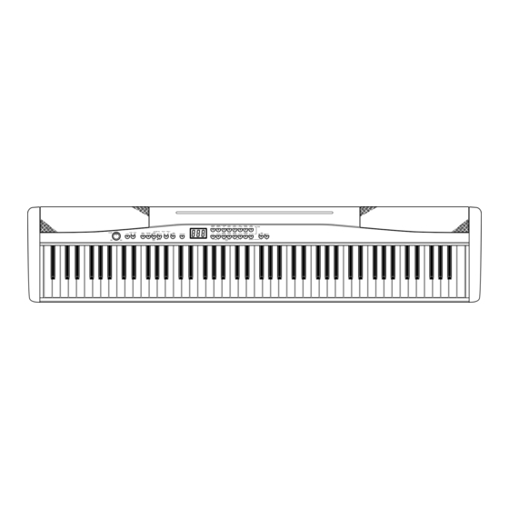
Casio PX-300 Service Manual
High-grade keyboard
Hide thumbs
Also See for PX-300:
- User manual (37 pages) ,
- Safety precautions (2 pages) ,
- Guía del usuario (36 pages)
Table of Contents
Advertisement
Quick Links
Advertisement
Table of Contents

Summary of Contents for Casio PX-300
- Page 1 PX-300 NOV. 2003 PX-300 HIGH-GRADE KEYBOARD INDEX Ver.5 : Jul. 2008...
-
Page 2: Table Of Contents
CONTENTS Specifications ---------------------------------------------------------------------------------------------- 1 Block Diagram --------------------------------------------------------------------------------------------- 2 Circuit Description --------------------------------------------------------------------------------------- 3 Printed Circuit Board ------------------------------------------------------------------------------------ 5 Disassembly ------------------------------------------------------------------------------------------------ 8 Diagnostic Program ------------------------------------------------------------------------------------ 12 Schematic Diagrams ----------------------------------------------------------------------------------- 14 Exploded View ------------------------------------------------------------------------------------------- 22 Parts List --------------------------------------------------------------------------------------------------- 23... -
Page 3: Specifications
Auto Accompaniment Number of Rhythms: Tempo Range: 30 to 255 Controllers: START/STOP, INTRO/ENDING, SYNCHRO/FILL-IN Modes: Normal; CASIO CHORD; FINGERED; FULL RANGE CHORD Accompaniment Volume: Adjustable Built-in Tunes Number of Tunes: 25 preset + 10 loaded song data Tempo: 30 to 255... -
Page 4: Block Diagram
BLOCK DIAGRAM — 2 —... -
Page 5: Circuit Description
CIRCUIT DESCRIPTION KEY MATRIX A0#1 C1#1 D1#1 A0#2 C1#2 D1#2 F1#1 G1#1 A1#1 F1#2 G1#2 A1#2 C2#1 D2#1 F2#1 G2#1 C2#2 D2#2 F2#2 G2#2 A2#1 C3#1 D3#1 A2#2 C3#2 D3#2 F3#1 G3#1 A3#1 F3#2 G3#2 A3#2 C4#1 D4#1 F4#1 G4#1 C4#2 D4#2 F4#2... - Page 6 BUTTON MATRIX MUSIC PERC ORGAN CHOIR PLAY/STOP G.PIANO 1 LIBRARY STRINGS TENORSAX METRONOME NORMAL G.PIANO 2 SONG AC.GUITAR FLUTE EASY HONKYTONK MEMORY LEFT/TRACK1 REVERB/ VIBRAPHONE AC.BASS E.PIANO 1 RIGHT/TRACK2 CHORUS HARPSICHORD GM TONES PIPE ORGAN E.PIANO 2 CONTROL VARIATION SPLIT —...
-
Page 7: Printed Circuit Board
PRINTED CIRCUIT BOARDS MAIN PCB M412-MAA1 — 5 —... - Page 8 Console PCB M412-CNA1 Vollume PCB M412-CNA2 Sub PCB M412-PS1 JACK PCB M412-PSA2 Power Switch PCB M412-PSA3 Pedal PCB M412-PSB4 — 6 —...
- Page 9 KEY PCB (MCPK-KYA1,KYB2,KYA3) — 7 —...
-
Page 10: Disassembly
DISASSEMBLY AND ASSEMBLY(*EQUIVALENT MODEL PX-500) 1. Remove 34 screws A at the bottom and then the base plate. 2. Remove ten screws B. Screw A × Screws B ( × Screws B ( Screw A 3. Turn the unit over so that the keyboard faces upward. 4. - Page 11 Removing the speaker 10. Remove two connectors and eight screws and then remove the speaker. Connector Connector Removing the MAIN PCB (M412-MAA1) 11. Remove five connectors and then the FPC. 12. Remove four screws and then the MAIN PCB (M412-MAA1). Connector Connector Removing the Volume PCB (M412-CNA2)
- Page 12 Removing the JACK PCB (M412-PSB4) 18. Remove three connectors. 19. Remove six screws and then the LED PCB (MCPK-LDC9). ConnectorÅ~2 Removing the JACK PCB (M412-PSB4) 20. Remove three connectors. 21. Remove five screws and then the LED PCB (MCPK-LDC9). Removing the keyboard 22.
- Page 13 Removing the LED PCB (MPCK-LDA1~LDA4, LDB5~LDB8) 23. Remove four connectors. 24. Remove four screws and the PCB for each PCB. * As for MPCK-LDA4 only, remove five screws. MPCK-LDA1 PCB MPCK-LDA2 PCB Connector MPCK-LDB5 PCB MPCK-LDB6 PCB MPCK-LDA3 PCB MPCK-LDA4 PCB Connector MPCK-LDB7 PCB MPCK-LDB8 PCB...
-
Page 14: Diagnostic Program
DIAGNOSTIC PROGRAM Initial Setup 1. Connect an AC adaptor. 2. Connect a Sustain pedal. 3. "Main" volume: MAX. NOTE: If there is no pedal or MIDI cable, pedal or MIDI check can be skipped. How to start diagnostic program 1. Press the “POWER” button while pressing the “REVERB/CHORUS KEY” buttons. 2. - Page 15 4. Headphone check 1 Press “CONTROL” button. *The confirmation chord of C4, E4 and G4 sounds. 2 Connect the headphone to the LEFT jack. * “CHORUS” LED lights. 3 Remove the headphone from the jack. * “REVERB” LED lights. 4 Connect the tuning meter to the RIGHT jack. * “CHORUS”...
-
Page 16: Schematic Diagrams
SCHEMATIC DIAGRAMS Main PCB M412-MAA1 — 14 —... - Page 17 Sub PCB M412-PS1 — 15 —...
- Page 18 Console PCB M412-CNA1 — 16 —...
- Page 19 JACK PCB M412-PSA2 — 17 —...
- Page 20 Volume PCB M412-CNA2 Pedal PCB M412-PSB4 Power Switch PCB M412-PSA3 — 18 —...
- Page 21 Key PCB MPCK-KYA1 — 19 —...
- Page 22 Key PCB MPCK-KYB2 — 20 —...
- Page 23 Key PCB MPCK-KYA3 — 21 —...
-
Page 24: Exploded View
EXPLODED VIEW — 22 —... -
Page 25: Parts List
PARTS LIST PX-300 Notes: This parts list does not include the cosmetic parts, which parts are marked with item No. "R-X" in the exploded view. Contact our spare parts department if you need these parts for refurbish. Prices and specifications are subject to change with- out prior notice. - Page 26 P r i c e I t e m Parts code Parts Name Specification Remarks Code MAIN PCB MAA1 10143170 PCB ASSY/MAIN TK-RJM503529*001 23902576 DIODE RB501V-40TE-17 10133383 DIODE 02DZ2.7-Z(TPH3) 10089360 TC7SZ02FU(TE85L) IC11,12 10047445 NJM2068M-D(T1) IC13 10129081 MEMORY CY62136VLL-55ZIT IC14 21056665 UPD63200GS-E1 IC15 69320063...
- Page 27 P r i c e I t e m Parts code Parts Name Specification Remarks Code E201 69324021 RELAY G5PA-28DC5V IC201 10040646 TC74HCT04AF(EL) IC202 69320061 PQ1CG21H2FZ IC203 10062671 LA4636 L201 10071755 COIL R187-860400 L202,203 10056228 COIL R2318-RB53-856397 Jack PCB PSB4 10143172 PCB ASSY/JACK TK-RJM503531*001...
- Page 28 P r i c e I t e m Parts code Parts Name Specification Remarks Code 10135272 KNOB/ROTARY RJM502503-004V01 10129871 BUTTON-TACT-M412A(2P) RJM502858-011V01 10129872 BUTTON-TACT-M412A(6P) RJM502858-012V01 10129873 BUTTON-TACT-M412A(1P) RJM502858-013V01 10129874 BUTTON-TACT-M412A(2P) RJM502858-014V01 69245260 BUTTON/POWER M340318-1 10143173 PCB ASSY/PSA TK-RJM503538*001 CN401 10136859 CONNECTOR HDC-052S-03 CN402...
- Page 29 Replacement of the EXPLODED VIEW (P22) Replacement of the PARTS LIST (P26) Ver.5 : Jul. 2008 Replacement of the EXPLODED VIEW (P22) Replacement of the PARTS LIST (P25) CASIO COMPUTER CO.,LTD. Overseas Service Division 6-2, Hon-machi 1-Chome Shibuya-ku, Tokyo 151-8543, Japan...


