
Related Manuals for LAWO A mic8

Summary of Contents for LAWO A mic8
- Page 1 A__mic8 / A__digital8 User Guide Version: 10.0.0/4 Edition: Wednesday, April 17, 2019 To obtain the latest documentation and software downloads, please visit: www.lawo.com/downloads...
- Page 2 All rights reserved. Permission to reprint or electronically reproduce any document or graphic in whole or in part for any reason is expressly prohibited, unless prior written consent is obtained from the Lawo AG. All trademarks and registered trademarks belong to their respective owners. It cannot be guaranteed that all product names, products, trademarks, requisitions, regulations, guidelines, specifications and norms are free from trade mark rights of third parties.
-
Page 3: Table Of Contents
Table of Contents Table of Contents 1. Introduction ............................4 2. Important Safety Instructions ........................ 5 3. Overview ............................. 6 4. Controls, Connectors & Indicators ......................7 5. The Streaming Ports ..........................9 6. Synchronization ..........................12 7. Installing the Unit ..........................14 8. -
Page 4: Introduction
· Lawo IP Networking Guide - more about the data network requirements and suitable components for AoIP. All Lawo manuals are available from the Downloads area at www.lawo.com (after Login). Look out for the following which indicate: Notes - points of clarification. -
Page 5: Important Safety Instructions
2. Important Safety Instructions Important Safety Instructions Please observe all of the instructions provided in the "General Safety Information for Lawo Equipment" booklet delivered with your devices. Double-click here to open the same information (as a pdf). A__mic8 / A__digital8 User Guide Version: 10.0.0/4... -
Page 6: Overview
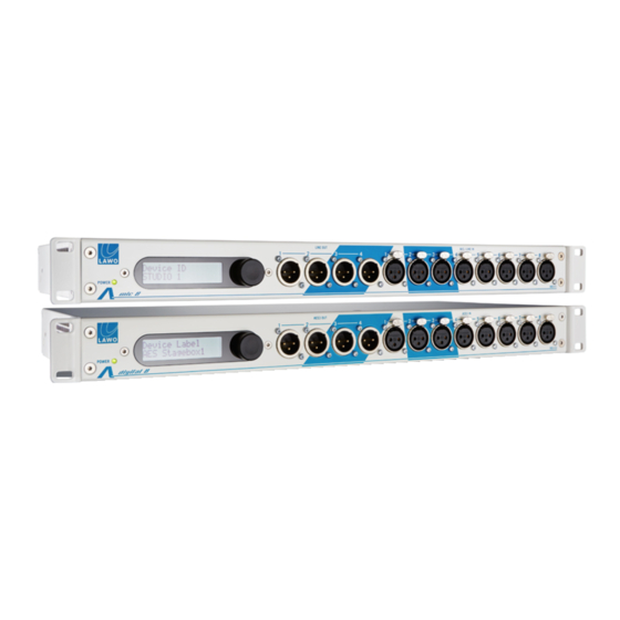
3. Overview Overview The A__mic8 and A__digital8 are members of Lawo's A__line series. Each 1RU, 19-inch unit provides a range of local inputs and outputs, plus two dual-redundant streaming ports for Audio over IP (AoIP). By networking multiple nodes, signals can be easily distributed between different device locations. -
Page 7: Controls, Connectors & Indicators
4. Controls, Connectors & Indicators Controls, Connectors & Indicators A__mic8 Status Display & Menu Control From here you can view and edit basic parameters such as the IP address of each streaming port. The POWER LED illuminates as soon as power is applied. 4 x LINE OUT Four line level outputs (XLR) for connection to local devices (balanced;... - Page 8 4. Controls, Connectors & Indicators The Wordclock output can be used to distribute the active sync source to other units via BNC. A__digital8 The A__digital8 is identical to the A__mic8 except for: 4 x AES3 OUT Four stereo AES3 outputs (XLR) for connection to local devices (balanced; floating; galvanic isolated; 110 Ω output impedance).
-
Page 9: The Streaming Ports
Please DO NOT attempt to connect RAVENNA interfaces using an unqualifying IP network, as correct streaming operation cannot be guaranteed. You can find more details about the data network requirements in the Lawo IP Networking Guide. Network Cables & Connectors... - Page 10 To configure SMPTE 2022-7 within a RAVENNA streaming network, will need to create the two separate paths for each data stream. This means doubling the network's infrastructure and then connecting each sending and receiving device to both paths. Within Lawo systems, the two paths are usually known as the primary (red) and secondary (blue) networks.
- Page 11 5. The Streaming Ports Port Labeling On the rear connector panel, the two streaming ports are labeled as ETHERNET A and ETHERNET B. However, on the front panel display and within the RAVENNA Web UI, they appear as ra0 and ra1. This is important to know when editing settings from the front panel or using the Web UI: Rear Connector Panel Network Interfaces (in the Web UI)
-
Page 12: Synchronization
6. Synchronization Synchronization Sync Reference Options The active sync source for the A__mic8 / A__digital8 is selected using the RAVENNA Web UI: Sync source options (A__mic8) Sync source options (A__digital8) For the A__mic8, you can choose one of three options: ·... - Page 13 RAVENNA Web UI (as described earlier). Installing a Grandmaster Device If you wish to install a third-party PTP master device, then Lawo recommends Meinberg clock generators. Alternatively, for networks utilizing SMPTE 2022-7, you could install a Lawo A__madi4. This brings a number of advantages: ·...
-
Page 14: Installing The Unit
1 x CAT5 to Coax Converter (optional) · 19" rack-mounting kit (optional) Please check the contents, and in the event of any transport damage, please contact your local Lawo representative or email support@lawo.com.. Install the frame. The unit is delivered with rack-mounting ears fitted to the sides of the frame - this is ideal for mounting the unit in a 19"... - Page 15 7. Installing the Unit Getting Operational Once the unit has booted the next steps are: Check and edit the network settings using the front panel display. IMPORTANT: Each streaming port must be given a unique IP address before it is connected to the network (to avoid IP conflicts).
-
Page 16: Front Panel Parameters
8. Front Panel Parameters Front Panel Parameters The front panel display and rotary control provide access to local device parameters: Turn the control to scroll through the available menus. Then push down to access the next level or edit the value. In each case, you can confirm all changes by pressing down on the o (ok) symbol. - Page 17 8. Front Panel Parameters Network Settings Device ID The Device ID must be a unique ID which identifies the unit within the IP network. Short, descriptive names are recommended. Use only normal characters, numbers and "_" or "-" without spaces. Up to 31 characters are permitted.
- Page 18 8. Front Panel Parameters System Menu The System menu provides access to the following options: Reboot Press down and then confirm to reboot the device. Once the reboot is complete, the latest settings will be restored. Factory Defaults Press down and then confirm to reset the device to the factory default settings. This operation will overwrite all existing settings and, therefore, should be used with caution! 18/66 Version: 10.0.0/4...
-
Page 19: Connecting A Service Computer
You can check the IP address of each streaming port from the device's front panel display. Ø Subnet Mask The Subnet Mask must match that of the port you are connecting to. In all Lawo systems, the default Subnet Mask = 255.255.255.0. Ø... -
Page 20: The Landing Page
10. The Landing Page The Landing Page The Landing Page provides access to all of resources required to configure the system. Note that the page does not adjust any settings directly, but provides a gateway to the HTML resources. 10.1 Opening the Landing Page Open your browser software, and enter the IP address of the device's ETHERNET port into the URL field. - Page 21 NEO CS data directory & Database - pages useful for Lawo support. · GPIOs - local GPIO control. · Service Support - can be used to download a snapshot of the settings (useful for Lawo support if there is a problem with the device). 10.3 Opening a HTML Resource...
-
Page 22: The Ravenna Web Ui
11. The RAVENNA Web UI The RAVENNA Web UI This chapter describes the RAVENNA Web UI, otherwise known as the "Butler" interface. 11.1 Applications For A__mic8 or A__digital8 devices, the RAVENNA Web UI is used for three main tasks: · To check and, if necessary, update the device firmware. - Page 23 11. The RAVENNA Web UI 11.4 Navigating to Other RAVENNA Devices Once the Home page is open, you can navigate to any other discovered device on the network. Click on Other RAVENNA Devices at the top right of the Home page: Choose an option from the drop-down list of devices - its Home page will open.
- Page 24 Up to 31 characters are permitted. To the right of the Lawo logo, you will also see a description of the device and the MAC address of the ra0 interface. These fields are for information only and cannot be edited.
- Page 25 11. The RAVENNA Web UI Network This area defines the network settings of the streaming ports. If the device supports SMPTE 2022-7 (streaming redundancy), then the ports are grouped into their SPS pairs. For example: strm0 = ra0 + ra1. Note that the group and port names are fixed and cannot be changed. For the A__mic8 / A__digital8, the IP Address, Network Mask and Gateway can be edited using the Web UI.
- Page 26 11. The RAVENNA Web UI Media This area lists all of the media which can be used for streaming. If the device supports more than one network interface, then each media is grouped into pairs: e.g. Audio-strm 0 = ra0 + ra1; Audio-strm 1 = ra2 + ra3. Note that this configuration is fixed;...
- Page 27 11. The RAVENNA Web UI 11.8 Defining the Network Interfaces From the Network area, click on an interface (e.g. ra0) to view its individual settings: Or, click on Other network settings to view the general settings applied to all ports: Use the fields to type in a value or select a menu option.
- Page 28 11. The RAVENNA Web UI 11.8.1 Network Interface Settings Ø Configuration The Configuration defines the network mode. The options are: · Static - select this mode to enter the IP Address, Network Mask and Gateway manually. · DHCP - select this mode to receive an IP Address automatically from the network's DHCP server. ·...
- Page 29 If you make a change, select Apply to confirm (or Cancel). Please refer to the Lawo IP Networking Guide for a more detailed explanation of PTP and how it should be implemented. Here we will provide a general description of the parameter fields.
- Page 30 11. The RAVENNA Web UI 11.10 Defining the Media From the Media area, click to view or edit the media's settings - options include the sample rate, sync source and PTP clock source. Note that these parameters will be applied to all of the media's sending (TX) streams. If the media has already been assigned to an active TX or RX stream, then it will be locked as shown below: To unlock a media, first close the window and use the Toggle...
- Page 31 11. The RAVENNA Web UI 11.10.1 Media Settings Ø Sample rate The Sample rate sets the sample rate of the RAVENNA media. For an A__line device, you can choose any of the available options. However, note that to sync to an external reference, the clocking signal MUST match the sample rate of the device.
- Page 32 11. The RAVENNA Web UI 11.11 TX Streams 11.11.1 Creating a TX Stream To publish audio from the device to the network, you will need to create a TX stream. Click on the Create button to open the TX stream properties: Use the fields to edit the properties.
- Page 33 11. The RAVENNA Web UI 11.11.2 TX Stream Properties Stream Settings Ø Name The Name will identify the stream to other network users and, therefore, cannot be edited later. It is recommended to use 6 characters or less with no special characters or spaces. Ø...
- Page 34 11. The RAVENNA Web UI The diagram below illustrates how the TX stream properties relate to other parts of the configuration: 34/66 Version: 10.0.0/4 A__mic8 / A__digital8 User Guide...
- Page 35 This results in a lower sending latency, but also a higher demand on the network's bandwidth. In Lawo devices, the Frame Size limits the number of TX streams which can be created by each device.
- Page 36 11. The RAVENNA Web UI 11.11.4 Interrogating & Editing TX Streams If you click on existing TX stream, then the fields can be edited as described earlier, apart from the following exceptions: Stream Settings · Name - the name cannot be edited once a stream has been published to the network. ·...
- Page 37 11. The RAVENNA Web UI 11.12 RX Streams 11.12.1 Creating a RX Stream To use audio from the network, you will need to create a RX stream. Click on the Connect button and choose a stream name from the drop-down menu - the 'RX Stream Properties' window appears.
- Page 38 OR switch one of the interfaces to not subscribed to receive the stream without redundancy. On all Lawo devices, you can use either interface of a streaming pair to receive single streams from the network. 38/66 Version: 10.0.0/4...
- Page 39 Syntonized mode should be enabled if the clock signal is missing from the SDP information, or if you have a different clock source selected at the sender and receiver. Syntonized mode should always be enabled for connections between Lawo audio and V__line devices. Syntonized mode should be disabled for AES67 or SMPTE 2110-30 compliance.
- Page 40 11. The RAVENNA Web UI 11.12.3 Using a Custom URL Whenever a TX stream is created, it's SDP (Session Description Protocol) information is announced to the rest of the network using RTSP / mDNS protocols. This means that providing the receiving device uses mDNS to collect SDP information AND can "see"...
- Page 41 11. The RAVENNA Web UI 11.12.4 Copying & Pasting SDP / RTSP URLs To copy and paste the SDP information from a sending device: Open a Web UI connection to the sending device, and click on the TX stream: At the bottom of the window, click on the SDP button to copy the stream's SDP information to the clipboard.
- Page 42 11. The RAVENNA Web UI A similar method can be used to copy and paste the RTSP URLs: On the sending device, use the RTSP URL buttons in the 'TX Stream Properties' window to copy the address for the sending interface. Then on the receiving device, paste the clipboard contents into the Stream Source field: If the TX stream is redundant, copy and paste the URL for the each of the sending interfaces separately - enter the ra0 URL into the upper field and the ra1 URL into the lower field.
- Page 43 11. The RAVENNA Web UI 11.12.5 The Statistics Window On the Home page, each RX stream name is color-coded to indicate the health of the stream: · Green = correct operation. · Red = there is either no connection or no data. ·...
- Page 44 11. The RAVENNA Web UI For a healthy stream (green) or one experiencing drop-outs (orange) you can click on Show Graphs for further details: Healthy RX Stream (Show Graphs) · Fractional Lost Packets - the number of lost packets over the last few seconds. ·...
- Page 45 11. The RAVENNA Web UI 11.13 Creating SMPTE 2022-7 Compatible Streams To support SMPTE 2022-7 (streaming redundancy), a stream must be transmitted and received via two separate network paths. For an A__line device, the TX or RX interfaces are ETHERNET A (ra0) + ETHERNET B (ra1). TX Stream Properties First, open a RAVENNA Web UI connection to the sending device and make sure that the 'TX Stream Properties' are configured to use both RAVENNA interfaces.
- Page 46 11. The RAVENNA Web UI RX Stream Properties: Pre-configured Now open a RAVENNA Web UI connection to the receiving device and, if possible, select the TX stream from the Connect menu - the 'RX Stream Properties' window opens. The Stream Source will be completed automatically from the stream's SDP information, and the Receiver Settings will be pre-configured according to the default settings.
- Page 47 11. The RAVENNA Web UI RX Stream Properties: Using a Custom URL If the TX stream does not appear in the Connect menu, then you will need to select Using a Custom URL define the Stream Source fields manually. As before, the simplest way to do this is to copy and paste the SDP or RTSP URLs from the sending device.
- Page 48 11. The RAVENNA Web UI 11.14 The Routing Matrix The Routing Matrix maps the device's local audio signals to and from the RAVENNA media. Together with the Recording track assignments (for TX streams) and Play track assignments (for RX streams), this determines the audio path to and from the network.
- Page 49 11. The RAVENNA Web UI 11.15 Batch Create The Batch Create function can be used to quickly create a series of similarly-configured TX or RX streams. For example: Use the Create button to open the 'TX Stream Properties' window and enter the parameters required for the first stream.
- Page 50 11. The RAVENNA Web UI 11.16 Selecting Streams You will need to select a stream to delete it or make it active or inactive via the Toggle button. In each case, the following methods can be applied to either TX or RX streams: Click on an individual entry to select (or deselect) the stream - the complete line is highlighted whenever a stream is selected.
- Page 51 11. The RAVENNA Web UI 11.18 Expert Settings Menu Once expert mode is enabled, you can click on Expert Settings to reveal the following options: Ø Disable edit mode Returns to the normal mode of operation. This is ideal if you wish to interrogate the configuration but do not need to edit any settings.
- Page 52 To check the Image version, select About from the headline at the top of the Home page to open the 'About' dialog box. To perform an update: Download the update file onto your computer. All releases are available from the Downloads area at www.lawo.com (after Login). Please check that the downloaded file ends with .tar.gz Some browsers, such as Safari, tend to unzip the file automatically after download which makes the file invalid.
-
Page 53: Adjusting Local Parameters
12. Adjusting Local Parameters Adjusting Local Parameters The Device Parameters and GPIO pages allow you to remotely control the audio and GPIO parameters from your service computer. Note that the latest values are stored locally on the device, and are re-instated following a power cycle or reboot. - Page 54 12. Adjusting Local Parameters 12.2 Device Parameters: A__mic8 On the left of the page, each Mic/Line In (1 to 8) is represented by a vertical channel strip, with MIC / LINE input selection. When switched to MIC, each input provides: ·...
- Page 55 12. Adjusting Local Parameters 12.3 Device Parameters: A__digital8 Across the top of the page, each AES3 In (1 to 8) is represented by a stereo channel with SRC ON / OFF to enable or disable the sample rate conversion, and input metering (in dBFS) for the left and right sides of the AES3 input.
- Page 56 12. Adjusting Local Parameters 12.4 GPIOs This page is identical for both the A__mic8 and A__digital8. At the top left, enable the GPIO Test Mode to loop all inputs to outputs. This can be useful for testing purposes. For normal operation, the Test Mode should be OFF. The two lower rows represent each individual input and output: ·...
-
Page 57: Software Tools & Diagnostics
13. Software Tools & Diagnostics Software Tools & Diagnostics 13.1 Configuration Backup & Restore This tool will backup and restore the complete RAVENNA configuration. It is ideal if you need to exchange a device. Note that this function is identical to the Backup and restore config function available from the Expert Settings menu of the RAVENNA Web UI. - Page 58 13. Software Tools & Diagnostics Ø To restore a configuration file: Open the Configuration backup & restore home page as before, but this time on the replacement unit. When you restore a configuration, you will override all of the device's RAVENNA settings. Therefore, make sure that you are connected to the correct unit before performing a restore! Click on the Browse button, select the backup file and then click on Open.
- Page 59 13. Software Tools & Diagnostics 13.2 Service Support This tool will download a current snapshot of the device settings into a "snaphot.sh" file. The file can be useful for Lawo support when diagnosing a problem. Ø To download the snapshot file: Open the Landing page in service mode, select Service Support and then click on the graphical preview.
- Page 60 All parameters within the A__mic8 / A__digital8 are accessible via Ember+. This allows an external control system, such as a Lawo console or VSM, to remotely control or respond to parameter changes within the device. From Image Version 10.0.0, this includes the internal Routing Matrix which maps the device's local IO signals to and from the RAVENNA streams.
- Page 61 13. Software Tools & Diagnostics 13.4 Running a PING Test The PING command is a built-in Windows and Mac function, that allows you to test whether you have a valid network connection to and from any networked device. Make sure that your computer is connected to the correct network port, and that you have configured the TCP/IP settings of your computer's network interface card.
- Page 62 13. Software Tools & Diagnostics Ø Ping Test Fail If the ping test fails, then the request will time out, and you will not receive any successful packets: There is something wrong with your network configuration, so check the network connections, and TCP/IP settings again.
-
Page 63: Glossary
Lawo's RAVENNA IO cards. DALLIS Digital and Line Level Interface System. The name of Lawo's configurable IO device. Each DALLIS frame can be fitted with a combination of plug-in IO cards. DHCP Dynamic Host Configuration Protocol Commonly used in data networks to dynamically allocate IP addresses from a central server. - Page 64 Network Interface Card A computer interface that connects to external network devices. Nova73 A stand alone routing matrix with networking capabilities; this is a large matrix related to the mc series of Lawo consoles. 64/66 Version: 10.0.0/4 A__mic8 / A__digital8 User Guide...
- Page 65 Remote MNOPL The remote control protocol RemoteMNOPL is a LAN based client-server network byte order protocol to enable third party systems to control Lawo’s digital mixing consoles or standalone routers. Real-time Transport Protocol A networking protocol that defines a standard packet format for delivering audio and video over data networks.
- Page 66 Time-Division Multiplexing A common method of transporting signals via a point-to-point connection. In Lawo devices, TDM is used internally to transport audio along the backplane - e.g. from a IO or DSP card to the routing matrix, and vice versa.