Table of Contents
Advertisement
Quick Links
Advertisement
Table of Contents

Summary of Contents for HIKVISION DS-TMT202-D
- Page 1 Exit Ticket Station (DS-TMT202-D) Quick Start Guide...
- Page 2 Exit Ticket Station • Quick Start Guide Symbol Conventions The symbols that may be found in this document are defined as follows. Symbol Description Provides additional information to emphasize or supplement important points of the main text. Indicates a potentially hazardous situation, which if not avoided, could result in equipment damage, data loss, performance degradation, or unexpected results.
-
Page 3: Chapter 1 Introduction
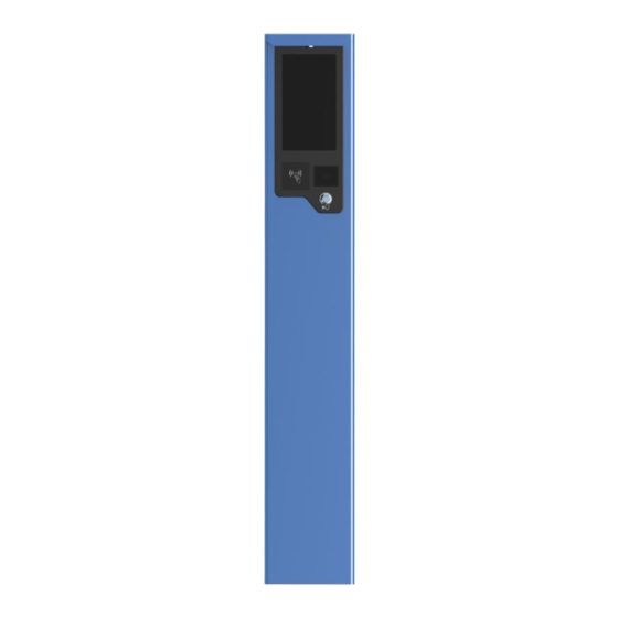
Exit Ticket Station • Quick Start Guide Chapter 1 Introduction Product Introduction Exit Ticket Station (hereinafter referred to as device) is used for data collection and management of exit and parking lot. Through interaction with the software, the device can control the exit, manage the parking lot effectively, and charge parking fee. - Page 4 Exit Ticket Station• Quick Start Guide Scanning area Scan QR code to pay parking fee. Loudspeaker Play voice prompt such as welcome.
-
Page 5: Chapter 2 Device Installation
Exit Ticket Station• Quick Start Guide Chapter 2 Device Installation Installation Environment Select the appropriate position for installing the device according to your actual requirement. Pay attention to the following tips. ● Install the device on horizontal ground. ● Installation surface requirements: ○... - Page 6 Exit Ticket Station• Quick Start Guide The pipe diameter of the pre-embedded cable should be no more than 60 mm. 2. Take the three M12 × 150 expansion screws out from the package. Punch the screws into the marked positions on refuge island. Fasten the nuts to make the screws expand to grip the ground.
- Page 7 Exit Ticket Station• Quick Start Guide Fix Device Wiring Cut off power before wiring. Steps 1. Connect the laid network cable to the network interface. 2. Connect the laid power cord (RVV3 × 1.5 mm² or above) to the power input of the device. 3.
- Page 8 Exit Ticket Station• Quick Start Guide 3. Lock the back cover with key. Lock Back Cover...
-
Page 9: Chapter 3 Device Configuration
Exit Ticket Station • Quick Start Guide Chapter 3 Device Configuration Scan the QR code below to get the user manual for detailed configuration. User Manual QR Code... - Page 10 UD35318B...