Table of Contents
Advertisement
Advertisement
Table of Contents

Related Manuals for Craftsman 917.2933


Summary of Contents for Craftsman 917.2933
- Page 1 Owner's Manual 17 iNCH TI WroTH COUNTER ROTATI TmLLE Model No. 917.293300 o Safety Assembly Operation o Maintenance Repair Parts CAUTION: Read and follow all Safety Rules and Instructions before operating this equipment Sears, Roebuck and Co., Hoffman Estates, IL 60179 ®...
- Page 2 Maintenance ... LIMITED TWO YEAR WARRANTY ON CRAFTSMAN TILLER For two (2) years from date of purchase, when this Craftsman Tiller is maintained, lubri- cated, and tuned up according to the operating and maintenance instructions in the owner's manual, Sears will repair free of charge any defect in material or workmanship.
-
Page 3: Operation
Always refer to the operator's guide instructionsfor important details if the tiller is to be stored for an extended peri- CAUTION: Always disconnect spark plug wire and place wire where it cannot contact spark plug in order to prevent acci- dental starting when setting up, transport- ing, adjusting or making repairs. -
Page 4: Spark Plug
These accessories were available when the tiller was purchased. able at most Sears Retail outlets and Service Centers. repair parts for you when you provide the model number of your tiller. ENGINE SPARK PLUG TILLER PERFORMANCE '"... -
Page 5: Operator's Position
Your new tiller has been assembled at the factory with exception of those parts left unassembled for shipping purposes. To ensure safe and proper operation of your tiller all parts and hardware you assemble must be tightened securely. Use the correct tools as necessary to insure proper tightness. - Page 6 Be sure handle lock remains in gearcase notch, Slide handle assembly into position, • Rotate handle assembly down. Insert rear carriage bolt first, with head of bolt on L,H. side of tiller and loosely assem- ble Iocknut. _;_,_, Handle Assembly ":".:..:. _._ ,,, .UP PosllJon _ "::_...
- Page 7 ° Tilt tiller forward by lifting handle. Separate cardboard cover from leveling shield° Cables o Rotate tiller handle to the right and pull tiller out of carton. CHECK TIRE PRESSURE The tires on your unit were overinflated at the factory for shipping purposes, and equal tire pressure is important for best tilling performance.
-
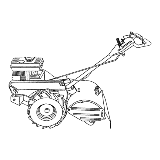
Page 8: Know Your Tiller
These symbols may appear on your Tiller or in literature Learn and understand their meaning, NEtrtRAL REVERSE CAUI'_GN OR WARNI_'_G KNOW YOUR TILLER READ THIS OWNER'S MANUALAND TILLER° Compare the illustrations with your tiller to familiarize ous controls and adjustments,... - Page 9 The operation of any tiller can result in foreign objects thrown into the eyes, which can result in severe eye damage. Always wear safety glasses or eye shields before starting your tiller and while tilling. We recommend a wide vision safety mask over the spectacles or standard safety glasses.
- Page 10 (both sides). Retighten nuts. TO TRANSPORT ,_kCAUTION: Before lifting or transport- ing, allow tiller engine and muffler to cool. Disconnect spark plug wire. Drain gaso- line from fuel tank. AROUND THE YARD ° Release the depth stake pin. Move the depth stake down to the top hole for transporting the tiller.
-
Page 11: To Start Engine
° Tilling is digging into, turning over, and breaking up packed soil before planting. Loose, unpacked soil helps root growth. Best tilling depth is 4" to 6". A tiller will also clear the soil of unwanted vegeta- tion. The decomposition of this veg- etable matter enriches the soil. - Page 12 T_NI= SHEAR PiNS The tine assemblies on your tiller are secured to the tine shaft with shear pins (See "TINE REPLACEMENT" Service and Adjustments section of this manual).
-
Page 13: Lubrication Chart
1 - Ch_,nga more oftenwhenoperating undera heavyload or in highambienttemperatures, 2- Servicemore oftenwhenoperating In dirtyor dust't c ortdtUons, GENERAL RECOMMENDATIONS The warranty on this tiller does not cover items that have been subjected to opera- tor abuse or negligence. To receive full value from the warranty, the operator must... -
Page 14: Air Filter
Change the oil after ever,./50 hours of operation or at least once a year if the tiller is not used for 50 hours in one year. Check the crankcase oil level before start- ing the engine and after each five (5) hours of continuous use. -
Page 15: Cooling System
° Retighten handle lock lever securely after adjusting. MUFFLER Do not operate tiller without muffler. Do not tamper with exhaust system_ Damaged mufflers or spark arresters could create a fire hazard. Inspect periodically and re- place if necessary. If your engine is... -
Page 16: Tire Care
When mounting tires, unless beads are seated, overinflation can cause an explosion. o Maintain 20 pounds of tire pressure. If tire pressures are not equal, tiller will pull to one side; o Keep tires free of gasoline or oil which can damage rubber. -
Page 17: Tine Replacement
Tines are sharp. Wear gloves or other protection when handling tines. A badly wom tine causes your tiller to work harder and dig more shallow. Most impor- tant, worn tines cannot chop and shred organic matter as effectively nor bury it as deeply as good tines. - Page 18 ENGINE Maintenance, repair, or replaceent of the emission control devices and systems, which are being done at the customers expense, may be performed by any non- road engine repair establishment or indi- vidual. Warranty repairs must be per- formed by an authorized engine manufac- turer's sercie outlet.
-
Page 19: Engine Oil
Allow the engine to cool before storing in any enclosure, TILLER o Clean entire tiller (See "CLEANING" the Customer Responsibilities this manual). o Inspect... - Page 20 CAUSE PROBLEM Will not start 1, Out of fuelo 2. Engine not "CHOKED" properly, 3, Engine flooded. 4. Dirty air cleaner. 5. Water in fuel. 6, Clogged fuel tank, 7. Loose spark plug wire. 8, Bad spark plug or improper gap, 9.
- Page 21 Ground too wet. Soil bails up or clumps 1,, "line control is not engaged° Engine runs but tiller won't move 2. V-belt not correctly adjusted. 3. V-belt is off pulley(s). 1_ Tilling too deep,, Engine runs but labors when tilling 2.
- Page 22 TILLER -- MODEL HANDLES PART DESCRIPTION 148583 Throttle, Control 141406 Gdp, Handle 110673X Grommet, Handle 127254X Bar, Drive Conirol Assembly 6712J Cap, Vinyl 137119 Panel, Control 110641X Bushing, Split 711910D8 *Screw, Pan Head #t0-24 72010520 *Boll, 5116-18 x 2-1t2 110646X...
-
Page 23: Left Side
TILLER - - MODEL MAINFRAME, LEFT SIDE DESCRIPTION PART STD541431 Nut, Keps 5/t6-18 STD551137 *Washer, Lock 3/8 STD541037 *Nut, Hex 3/8-16 74930568 Bolt, Hex 5/16-18 x 4-!!4 154734 Screw Shift Lever 110111X Lever, Shift STD532505 *Bolt, Carriage 1/'4-20 x 112Gr. - Page 24 TILLER .. - MODEL MAINFRAME, RIGHT SIDE PART DESCRIPTION STD54143t *Nut,Keps 5/16-18 102332X Bracket, R einforcement 7476O524 Bolt, H ex 5116o18 x 1-1/2 102t73X CounterWeight, RH° STD551137 *Washer, L ock 3/8 STD541037 *Nut, Hex 3/8-16 STD624003 "Clip,Hairpin 126875){ Rivet,Drilled 5015,t...
- Page 25 T6LLER - - MODEL TRANSMISSION DESCRIPTION PART 154354 TransmissionAssembly (Includes Key Nos.. 2-52) 150698 Gearcase, LH. w/Bearing (Includes Key No. 4) 106211X Gasket, Gearcase 5020J Beadng, Needle 1370H Washer, Thrust 5/8 x 1.10 x 1/32 137335 Pinion, Input 145101 Shaft, Input 4895H Bearing, Needle 154467...
- Page 26 TILLER = = MODEL NUMBER 917.293300 TINE SHIELD PART DESCRIPTION 98000129 Nut,Range 5/16_18 t61415x574 Shield,Side,OuterL. H. 8393J Pin,Stake,Depth 12000036 Ring,Klfp STD533107 *Bolt,Carriage5/16-18x 3/4 Gr 8394J Spring Bracket, L atch 8392J 109230)( Spring,DepthStake 124289X574 Shield, *Bolt,Carriage5/16-t8 x I Gro 5 STD533110...
-
Page 27: Tine Assembly
TILLER - - MODEL TINE ASSEMBLY PART DESCRIPTION 44593 Tine, Outer, LH. 132673 Pin, Shear 6554j Tine, Inner, LHo STD624008 *Clip, Halrptn 132727 Assembly, Hub and Plate, Loll. 73610600 Nut, Hex 316-24 STD551137 *Washer, Lock 3/8 74610616 Bolt, Hex 3/8-24 x 1... - Page 28 TILLER - =MODEL NUMBER 917.293300 DECALS PART DESCRIPTION 158096 Decat, Logo 157991 Decal, Logo 157990 Decal, Logo 157984 Decal, Description 137539 Decal, Caution, Drive Control 12043tX Decal, Hand Placement 102180X Decal, Shift Indicator 147592 Decal, Operation and Lubrication 163094 Decal, Depth Stake...
- Page 29 i = w_n_w_v_ww ENGINE, BRIGGS & ST_ATTON - - MODEL NUMBER 134402, TYPE NO. 1113-E1 _" REQUIRES SPECIAL TOOLS TO INSTALL, SEE REPAIR 337_ INSTRUCTION MANUAL _562 ... _184...
- Page 30 TILLER - - MODEL NUMBER 917.293300 ENGINE, BRIGGS & STRATTON- .. MODEL NUMBER 134402, TYPE NO. 1113-E1 219 _ l_r REQUIRES SPECLAL TOOLS TO INSTALL SEE REPAIR INSTRUCTION MANUAL,...
- Page 31 TRLLER - - MODEL NUMBER 917.293300 ENGINE, BRIGGS & STRATTON _) 634 634A 111_:_ lo9_ ... VALVE OVERHAUL GASKET SET 634A @oo,® 977 CARBURETOR GASKET SET - - MODEL NUMBER 134402, TYPE NO. 1"113-E1 358 GASKET SET 121 CARBURETOR KIT , llll u,,_..2 634A...
- Page 32 TILLER .,- MODEL NUMBER 917.293300 ENGINE, BRIGGS & STRATTON - - MODEL NUMBER 134402, TYPE NO. 1113-E1 _305 843A...
- Page 33 TILLER - - MODEL NUMBER 917.293300 ENGINE, BRIGGS & STRATTON PART DESCRIPTION 495133 CylinderAssembSy 399268 Bushing 299819 Seal, Oil 214040 Head, Cylinder 272157 Gasket, Cylinder Head 495774 BreathsrAssembly 27549 Gasket, Breather 94621 Screw, Breather Mounting 66578 Grommet 270080 Gasket, Crankcase, .O15" Thick...
- Page 34 TRLLER - - MODEL ENGINE, BRIGGS & STRATTON - - MODEL NUMBER 134402, TYPE NO. 1113-E1 PART DESCRIPTION 498593 Shaft, Choke 280871 Support, Air Cleaner Gasket, Air Cleaner 272537 281247 Manifold, Intake 94692 Nut, Wing 224669 Bracket, Fue! Tank Screw, Hex Head 94905 Nut, Hex 94010...
- Page 36 For the repair or replacement parts you need delivered directly to your home Call 7 am - 7 pro, 7 days a week 1-800=306-PART (1-800-366-7278) Para ordenar piezas con entrega a domicilio - 1-800-659-7084 For in-house major brand repair service Call 24 hours a day, 7 days a week 1-800-4oREPAHR (1-800-473-7274)