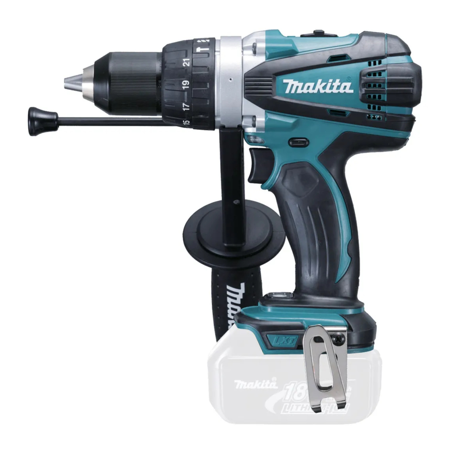
Makita BHP448, BHP458 - Cordless Hammer Driver Drill Manual
- Instruction manual (65 pages) ,
- Technical information (12 pages) ,
- Instruction manual (17 pages)
Advertisement
- 1 Explanation of general view
- 2 SPECIFICATIONS
- 3 General Power Tool Safety Warnings
- 4 CORDLESS HAMMER DRIVER DRILL SAFETY WARNINGS
- 5 IMPORTANT SAFETY INSTRUCTIONS FOR BATTERY CARTRIDGE
-
6
FUNCTIONAL DESCRIPTION
- 6.1 Installing or removing battery cartridge
- 6.2 Battery protection system (Lithium-ion battery with star marking)
- 6.3 Switch action
- 6.4 Lighting up the front lamp
- 6.5 Reversing switch action
- 6.6 Speed change
- 6.7 Selecting the action mode
- 6.8 Adjusting the fastening torque
- 6.9 Empty signal for remaining battery capacity
- 7 ASSEMBLY
- 8 OPERATION
- 9 MAINTENANCE
- 10 OPTIONAL ACCESSORIES
- 11 Documents / Resources
Explanation of general view
![]()
- Red indicator
- Button
- Battery cartridge
![]()
- Star marking
![]()
- Switch trigger
![]()
- Lamp
![]()
- Reversing switch lever
![]()
- Speed change lever
![]()
- Action mode changing ring
- Arrow
![]()
- Adjusting ring
- Graduation
- Arrow
![]()
- Button
- LED indicator
![]()
- Groove
- Protrusion
- Steel band
- Grip base
- Side grip
![]()
- Sleeve
![]()
- Bit holder
- Bit
![]()
- Depth rod
- Clamp screw
![]()
- Groove
- Hook
- Screw


![]()
- Blow-out bulb
![]()
- Limit mark
![]()
- Rear cover
- Screws
![]()
- Arm
- Spring
- Recessed part
![]()
- Carbon brush cap
![]()
- Hole
- Carbon brush cap


SPECIFICATIONS
| Model | BHP448 | BHP458 | |
| Capacities | Drilling into concrete | 14 mm | 16 mm |
| Drilling into steel | 13 mm | 13 mm | |
| Drilling into wood | 65 mm | 76 mm | |
| Fastening wood screw | 8 mm x 75 mm | 10 mm x 90 mm | |
| Fastening machine screw | 6 mm | ||
| No load speed | High (2) | 0 - 1,800 min-1 | 0 - 2,000 min-1 |
| Low (1) | 0 - 350 min-1 | 0 - 400 min-1 | |
| Blows per minute | High (2) | 0 - 27,000 min-1 | 0 - 30,000 min-1 |
| Low (1) | 0 - 5,200 min-1 | 0 - 6,000 min-1 | |
| Overall length | 225 mm | ||
| Net weight | 2.2 kg | 2.3 kg | |
| Rated voltage | D.C. 14.4 V | D.C. 18 V | |
- Due to our continuing program of research and development, the specifications herein are subject to change without notice.
- Specifications and battery cartridge may differ from country to country.
- Weight, with battery cartridge, according to EPTA-Procedure 01/2003
Intended use
The tool is intended for impact drilling in brick, concrete and stone. It is also suitable for screw driving and drilling without impact in wood, metal, ceramic and plastic.
Noise
The typical A-weighted noise level determined according to EN60745:
Model BHP448
Sound pressure level (LpA): 82 dB(A)
Sound power level (LWA): 93 dB(A)
Uncertainty (K): 3 dB(A)
Model BHP458
Sound pressure level (LpA): 84 dB(A)
Sound power level (LWA): 95 dB(A)
Uncertainty (K): 3 dB(A)
Wear ear protection
Vibration
The vibration total value (tri-axial vector sum) determined according to EN60745:
Model BHP448
Work mode: impact drilling into concrete
Vibration emission (ah, ID): 8.5 m/s2
Uncertainty (K): 1.5 m/s2
Work mode: drilling into metal
Vibration emission (ah, D): 2.5 m/s2 or less
Uncertainty (K): 1.5 m/s2
Model BHP458
Work mode: impact drilling into concrete
Vibration emission (ah, ID): 9.5 m/s2
Uncertainty (K): 1.5 m/s2
Work mode: drilling into metal
Vibration emission (ah, D): 2.5 m/s2 or less
Uncertainty (K): 1.5 m/s2
- The declared vibration emission value has been measured in accordance with the standard test method and may be used for comparing one tool with another.
- The declared vibration emission value may also be used in a preliminary assessment of exposure.

- The vibration emission during actual use of the power tool can differ from the declared emission value depending on the ways in which the tool is used.
- Be sure to identify safety measures to protect the operator that are based on an estimation of exposure in the actual conditions of use (taking account of all parts of the operating cycle such as the times when the tool is switched off and when it is running idle in addition to the trigger time).
General Power Tool Safety Warnings
Read all safety warnings and all instructions. Failure to follow the warnings and instructions may result in electric shock, fire and/or serious injury.
Save all warnings and instructions for future reference.
CORDLESS HAMMER DRIVER DRILL SAFETY WARNINGS
- Wear ear protectors with impact drilling. Exposure to noise can cause hearing loss.
- Use auxiliary handle(s), if supplied with the tool. Loss of control can cause personal injury.
- Hold power tool by insulated gripping surfaces, when performing an operation where the cutting accessory may contact hidden wiring. Cutting accessory contacting a "live" wire may make exposed metal parts of the power tool "live" and could give the operator an electric shock.
- Hold power tool by insulated gripping surfaces, when performing an operation where the fastener may contact hidden wiring. Fasteners contacting a "live" wire may make exposed metal parts of the power tool "live" and could give the operator an electric shock.
- Always be sure you have a firm footing. Be sure no one is below when using the tool in high locations.
- Hold the tool firmly.
- Keep hands away from rotating parts.
- Do not leave the tool running. Operate the tool only when hand-held.
- Do not touch the bit or the workpiece immediately after operation; they may be extremely hot and could burn your skin.
- Some material contains chemicals which may be toxic. Take caution to prevent dust inhalation and skin contact. Follow material supplier safety data.
SAVE THESE INSTRUCTIONS.
DO NOT let comfort or familiarity with product (gained from repeated use) replace strict adherence to safety rules for the subject product. MISUSE or failure to follow the safety rules stated in this instruction manual may cause serious personal injury.
IMPORTANT SAFETY INSTRUCTIONS FOR BATTERY CARTRIDGE
- Before using battery cartridge, read all instructions and cautionary markings on (1) battery charger, (2) battery, and (3) product using battery.
- Do not disassemble battery cartridge.
- If operating time has become excessively shorter, stop operating immediately. It may result in a risk of overheating, possible burns and even an explosion.
- If electrolyte gets into your eyes, rinse them out with clear water and seek medical attention right away. It may result in loss of your eyesight.
- Do not short the battery cartridge:
- Do not touch the terminals with any conductive material.
- Avoid storing battery cartridge in a container with other metal objects such as nails, coins, etc.
- Do not expose battery cartridge to water or rain.
A battery short can cause a large current flow, overheating, possible burns and even a breakdown.
- Do not store the tool and battery cartridge in locations where the temperature may reach or exceed 50ºC (122º F).
- Do not incinerate the battery cartridge even if it is severely damaged or is completely worn out. The battery cartridge can explode in a fire.
- Be careful not to drop or strike battery.
- Do not use a damaged battery.
SAVE THESE INSTRUCTIONS.
Tips for maintaining maximum battery life
- Charge the battery cartridge before completely discharged.
Always stop tool operation and charge the battery cartridge when you notice less tool power. - Never recharge a fully charged battery cartridge.
Overcharging shortens the battery service life. - Charge the battery cartridge with room temperature at 10ºC - 40ºC (50º F - 104º F). Let a hot battery cartridge cool down before charging it.
- Charge the battery cartridge once in every six months if you do not use it for a long period of time.
FUNCTIONAL DESCRIPTION

- Always be sure that the tool is switched off and the battery cartridge is removed before adjusting or checking function on the tool.
Installing or removing battery cartridge
Fig.1
- Always switch off the tool before installing or removing of the battery cartridge.
To remove the battery cartridge, slide it from the tool while sliding the button on the front of the cartridge.
To install the battery cartridge, align the tongue on the battery cartridge with the groove in the housing and slip it into place. Insert it all the way until it locks in place with a little click. If you can see the red indicator on the upper side of the button, it is not locked completely.
- Always install the battery cartridge fully until the red indicator cannot be seen. If not, it may accidentally fall out of the tool, causing injury to you or someone around you.
- Do not use force when installing the battery cartridge. If the cartridge does not slide in easily, it is not being inserted correctly.
Battery protection system (Lithium-ion battery with star marking)
Fig.2
Lithium-ion batteries with a star marking are equipped with a protection system. This system automatically cuts off power to the tool to extend battery life.
The tool will automatically stop during operation if the tool and/or battery are placed under one of the following conditions:
- Overloaded:
The tool is operated in a manner that causes it to draw an abnormally high current.
In this situation, release the switch trigger on the tool and stop the application that caused the tool to become overloaded. Then pull the switch trigger again to restart.
If the tool does not start, the battery is overheated. In this situation, let the battery cool before pulling the switch trigger again. - Low battery voltage:
The remaining battery capacity is too low and the tool will not operate. In this situation, remove and recharge the battery.
Switch action
Fig.3
- Before inserting the battery cartridge into the tool, always check to see that the switch trigger actuates properly and returns to the "OFF" position when released.
To start the tool, simply pull the switch trigger. Tool speed is increased by increasing pressure on the switch trigger. Release the switch trigger to stop.
Lighting up the front lamp
Fig.4
- Do not look in the light or see the source of light directly.
Pull the switch trigger to light up the lamp. The lamp keeps on lighting while the switch trigger is being pulled. The lamp goes out 10 -15 seconds after releasing the trigger.
NOTE:
- Use a dry cloth to wipe the dirt off the lens of lamp. Be careful not to scratch the lens of lamp, or it may lower the illumination.
Reversing switch action
Fig.5
This tool has a reversing switch to change the direction of rotation. Depress the reversing switch lever from the A side for clockwise rotation or from the B side for counterclockwise rotation.
When the reversing switch lever is in the neutral position, the switch trigger cannot be pulled.
- Always check the direction of rotation before operation.
- Use the reversing switch only after the tool comes to a complete stop. Changing the direction of rotation before the tool stops may damage the tool.
- When not operating the tool, always set the reversing switch lever to the neutral position.
Speed change
Fig.6
To change the speed, first switch off the tool and then slide the speed change lever to the "2" side for high speed or, "1" side for low speed. Be sure that the speed change lever is set to the correct position before operation. Use the right speed for your job.
- Always set the speed change lever fully to the correct position. If you operate the tool with the speed change lever positioned halfway between the "1" side and "2" side, the tool may be damaged.
- Do not use the speed change lever while the tool is running. The tool may be damaged.
Selecting the action mode
Fig.7
This tool employs an action mode changing ring. Select one of the three modes suitable for your work needs by using this ring.
For rotation only, turn the ring so that the arrow on the tool body points toward the  mark on the ring.
For rotation with hammering, turn the ring so that the arrow points toward the  mark on the ring.
For rotation with clutch, turn the ring so that the arrow points toward the ![]() mark on the ring.
mark on the ring.
- Always set the ring correctly to your desired mode mark. If you operate the tool with the ring positioned halfway between the mode marks, the tool may be damaged.
Adjusting the fastening torque
(screwdriver mode " ![]() ")
")
Fig.8
The fastening torque can be adjusted in 21 steps by turning the adjusting ring so that its graduations are aligned with the pointer on the tool body.
First, slide the action mode change lever to the position of ![]() symbol.
symbol.
The fastening torque is minimum when the number 1 is aligned with the pointer, and maximum when the marking is aligned with the pointer. The clutch will slip at various torque levels when set at the number 1 to 21.
Before actual operation, drive a trial screw into your material or a piece of duplicate material to determine which torque level is required for a particular application.
NOTE:
- The adjusting ring does not lock when the pointer is positioned only halfway between the graduations.
Empty signal for remaining battery capacity
Fig.9
Stop the tool and with the tool stopped press the button on the switch panel and the remaining battery capacity will be signaled on the panel.
The status displayed on the switch panel and the remaining battery capacity is shown in the following table.
| LED indicator status | Remaining battery capacity |
 | About 50% or more |
 | About 20% - 50% |
 | About less than 20% |
NOTE:
- Before checking the remaining battery capacity, be sure to stop the tool.
ASSEMBLY
- Always be sure that the tool is switched off and the battery cartridge is removed before carrying out any work on the tool.
Installing side grip (auxiliary handle)
Fig.10
Always use the side grip to ensure operating safety.
Insert the side grip so that the protrusions on the grip base and steel band fit in between the grooves on the tool barrel. Then tighten the grip by turning clockwise.
When you turn the side grip, loosen and remove the grip, then turn the grip and insert it again.
Installing or removing driver bit or drill bit
Fig.11
Turn the sleeve counterclockwise to open the chuck jaws. Place the bit in the chuck as far as it will go. Turn the sleeve clockwise to tighten the chuck. To remove the bit, turn the sleeve counterclockwise.
Installing bit holder
Fig.12
Fit the bit holder into the protrusion at the tool foot on either right or left side and secure it with a screw.
When not using the driver bit, keep it in the bit holders. Bits 45 mm long can be kept there.
Adjustable depth rod
Fig.13
The adjustable depth rod is used to drill holes of uniform depth. Loosen the clamp screw, set to desired position, then tighten the clamp screw.
Hook
Fig.14
The hook is convenient for temporarily hanging the tool. This can be installed on either side of the tool.
To install the hook, insert it into a groove in the tool housing on either side and then secure it with a screw.
To remove, loosen the screw and then take it out.
OPERATION
Fig.15

Hammer drilling operation
- There is a tremendous and sudden twisting force exerted on the tool/bit at the time of hole break-through, when the hole becomes clogged with chips and particles, or when striking reinforcing rods embedded in the concrete. Always use the side grip (auxiliary handle) and firmly hold the tool by both side grip and switch handle during operations. Failure to do so may result in the loss of control of the tool and potentially severe injury.
First, slide the action mode change lever so that it points to the ![]() marking. The adjusting ring can be aligned in any torque levels for this operation.
marking. The adjusting ring can be aligned in any torque levels for this operation.
Be sure to use a tungsten-carbide tipped bit.
Position the bit at the desired location for the hole, then pull the switch trigger. Do not force the tool. Light pressure gives best results. Keep the tool in position and prevent it from slipping away from the hole.
Do not apply more pressure when the hole becomes clogged with chips or particles. Instead, run the tool at an idle, then remove the bit partially from the hole. By repeating this several times, the hole will be cleaned out and normal drilling may be resumed.
Blow-out bulb (optional accessory)
Fig.16
After drilling the hole, use the blow-out bulb to clean the dust out of the hole.
Screwdriving operation
First, slide the action mode change lever so that it points to the ![]() marking. Adjust the adjusting ring to the proper torque level for your work. Then proceed as follows.
marking. Adjust the adjusting ring to the proper torque level for your work. Then proceed as follows.
Place the point of the driver bit in the screw head and apply pressure to the tool. Start the tool slowly and then increase the speed gradually. Release the switch trigger as soon as the clutch cuts in.
NOTE:
- Make sure that the driver bit is inserted straight in the screw head, or the screw and/or bit may be damaged.
- When driving wood screw, predrill a pilot hole 2/3 the diameter of the screw. It makes driving easier and prevents splitting of the workpiece.
- If the tool is operated continuously until the battery cartridge has discharged, allow the tool to rest for 15 minutes before proceeding with a fresh battery.
Drilling operation
- Pressing excessively on the tool will not speed up the drilling. In fact, this excessive pressure will only serve to damage the tip of your bit, decrease the tool performance and shorten the service life of the tool.
- There is a tremendous force exerted on the tool/bit at the time of hole break through. Hold the tool firmly and exert care when the bit begins to break through the workpiece.
- A stuck bit can be removed simply by setting the reversing switch to reverse rotation in order to back out. However, the tool may back out abruptly if you do not hold it firmly.
- Always secure small workpieces in a vise or similar hold-down device.
- If the tool is operated continuously until the battery cartridge has discharged, allow the tool to rest for 15 minutes before proceeding with a fresh battery.
First, slide the action mode change lever so that it points to the ![]() marking. The adjusting ring can be aligned in any torque levels for this operation. Then proceed as follows.
marking. The adjusting ring can be aligned in any torque levels for this operation. Then proceed as follows.
Drilling in wood
When drilling in wood, the best results are obtained with wood drills equipped with a guide screw. The guide screw makes drilling easier by pulling the bit into the workpiece.
Drilling in metal
To prevent the bit from slipping when starting a hole, make an indentation with a center-punch and hammer at the point to be drilled. Place the point of the bit in the indentation and start drilling.
Use a cutting lubricant when drilling metals. The exceptions are iron and brass which should be drilled dry.
MAINTENANCE
- Always be sure that the tool is switched off and the battery cartridge is removed before attempting to perform inspection or maintenance.
- Never use gasoline, benzine, thinner, alcohol or the like. Discoloration, deformation or cracks may result.
Replacing carbon brushes
Fig.17
Replace when they wear down to the limit mark. Keep the carbon brushes clean and free to slip in the holders. Both carbon brushes should be replaced at the same time. Use only identical carbon brushes.
Fig.18
Use a screwdriver to remove two screws then remove the rear cover.
Fig.19
Raise the arm part of the spring and then place it in the recessed part of the housing with a slotted bit screwdriver of slender shaft or the like.
Fig.20
Use pliers to remove the carbon brush caps of the carbon brushes. Take out the worn carbon brushes, insert the new ones and replace the carbon brush caps in reverse.
Fig.21
Make sure that the carbon brush caps have fit into the holes in brush holders securely.
Reinstall the rear cover and tighten two screws securely. To maintain product SAFETY and RELIABILITY, repairs, any other maintenance or adjustment should be performed by Makita Authorized Service Centers, always using Makita replacement parts.
OPTIONAL ACCESSORIES
- These accessories or attachments are recommended for use with your Makita tool specified in this manual. The use of any other accessories or attachments might present a risk of injury to persons. Only use accessory or attachment for its stated purpose.
If you need any assistance for more details regarding these accessories, ask your local Makita Service Center.
- Drill bits
- Hammer drill bits
- Screw bits
- Blow-out bulb
- Safety goggles
- Makita genuine battery and charger
- Grip assembly
- Depth rod
- Hook
- Rubber pad assembly
- Wool bonnet
- Foam polishing pad
- Battery protector
NOTE:
- Some items in the list may be included in the tool package as standard accessories. They may differ from country to country.

Documents / ResourcesDownload manual
Here you can download full pdf version of manual, it may contain additional safety instructions, warranty information, FCC rules, etc.
Download Makita BHP448, BHP458 - Cordless Hammer Driver Drill Manual
Advertisement
Thank you! Your question has been received!


Need Assistance?
Do you have a question about the BHP448 that isn't answered in the manual? Leave your question here.