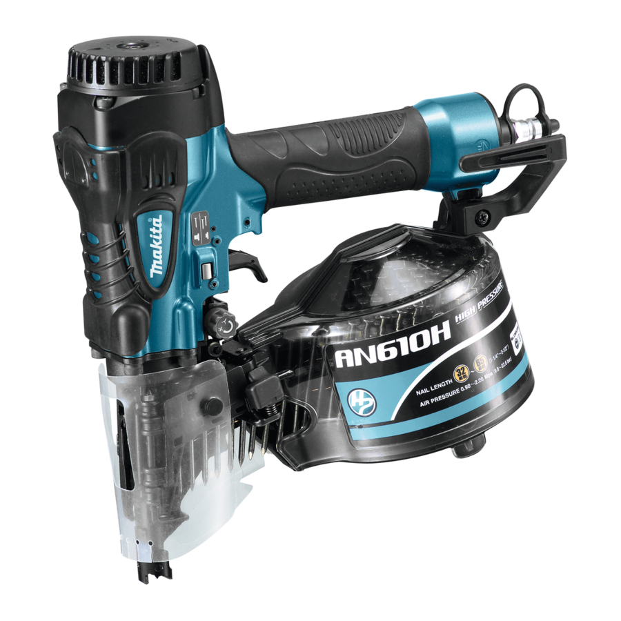
Makita AN610H - Construction Nailer Manual
- Instruction manual (65 pages) ,
- Instruction manual (61 pages) ,
- Instruction manual (57 pages)
Advertisement
Explanation of general view
![]()
- Adjuster
- Shallow
- Deep
![]()
- Too deep
- Flush
- Too shallow
![]()
- Hook
![]()
- Hole
- Protrusion
- Nose adapter
![]()
- Magazine cap
- Latch lever
- Door
![]()
- Adjustfit
- Change plate
- Arrow
![]()
- Door
- Nail guide
- Feeder
![]()
- Trigger
- Contact element
![]()
- Trigger
- Contact element
![]()
- Change lever
- Trigger
![]()
- Change lever
- Trigger
![]()
- 0.7 mm or less thick for a steel plate
- Thickness of workpiece
- 10 mm or more
- C-shaped steel (Thickness 1.6 mm - 2.3 mm)
![]()
- Nail driven to a proper depth
- Nail driven too deep will cause deformation of workpieces
![]()
- Nail length
- Wood thickness
- Concrete range 10 - 15 mm
![]()
![]()
- Small rod
![]()
- Screwdriver
![]()
- Cap
![]()
- Drain cock


SPECIFICATIONS
| Model | AN610H |
| Air pressure | 0.98 - 2.26 MPa (9.8 - 22.6 bar) |
| Nail length | Wire-collated coil nail 32 mm - 65 mm Sheet-collated coil nail 32 mm - 65 mm |
| Nail capacity | Wire-collated coil nail 250 pcs., 300 pcs., 400 pcs. Sheet-collated coil nail 200 pcs. |
| Min. hose diameter | 5.0 mm |
| Pneumatic tool oil | ISO VG32 or equivalent |
| Dimensions (L X H X W) | 282 mm X 277 mm X 136 mm |
| Net weight | 1.9 kg |
- Due to our continuing program of research and development, the specifications herein are subject to change without notice.
- Specifications may differ from country to country.
- Weight according to EPTA-Procedure 01/2003
Symbols
The following show the symbols used for the equipment. Be sure that you understand their meaning before use.
 |
|
 |
|
 |
|
Intended use
The tool is intended for the preliminary interior work such as fixing floor joists or common rafters and framing work in 2 "x 4" housing.
Noise
The typical A-weighted noise level determined according to EN792:
Sound pressure level (LpA): 86 dB (A)
Sound power level (LWA): 99 dB (A)
Uncertainty (K): 3 dB (A)
Wear ear protection
Vibration
The vibration total value determined according to EN792:
Vibration emission (ah): 3.0 m/s2
Uncertainty (K): 1.5 m/s2
- The declared vibration emission value has been measured in accordance with the standard test method and may be used for comparing one tool with another.
- The declared vibration emission value may also be used in a preliminary assessment of exposure.

- The vibration emission during actual use of the power tool can differ from the declared emission value depending on the ways in which the tool is used.
- Be sure to identify safety measures to protect the operator that are based on an estimation of exposure in the actual conditions of use (taking account of all parts of the operating cycle such as the times when the tool is switched off and when it is running idle in addition to the trigger time).
Pneumatic nailer/stapler safety warnings
Read all safety warnings and all instructions. Failure to follow the warnings and instructions may result in serious injury, electric shock and/or fire.
Save all warnings and instructions for future reference.
For personal safety and proper operation and maintenance of the tool, read this instruction manual before using the tool.
General safety
- Do not permit those uninstructed to use the tool. No horseplay. Respect the tool as a working implement.
- Do not operate when under the influence of
- alcohol, drugs or the like.
- Never alter the tool.
Personal protective equipments
- Always wear safety glasses to protect your eyes from dust or fastener injury.
![]()
It is an employer's responsibility to enforce the use of safety eye protection equipment by the tool operators and by other persons in the immediate working area.
For Australia and New Zealand only Always wear safety glasses and face shield to protect your eyes from dust or fastener injury. The safety glasses and the face shield should conform with the requirements of AS/NZS 1336.

- Wear hearing protection to protect your ears against exhaust noise and head protection. Also wear light but not loose clothing. Sleeves should be buttoned or rolled up. No necktie should be worn.

Work area safety
- Keep work area clean and well lit. Cluttered or dark areas invite accidents.
- Do not operate the tool in explosive atmospheres, such as in the presence of flammable liquids, gases or dust. Operating the tool can create sparks which may ignite the dust or fumes.
- Keep children and bystanders away while operating the tool. Distractions can cause you to lose control.
- Illuminate the work area sufficiently.
- There may be local regulations concerning noise which must be complied with by keeping noise levels within prescribed limits. In certain cases, shutters should be used to contain noise.
Safety devices
- Make sure all safety systems are in working order before operation. The tool must not operate if only the trigger is pulled or if only the contact arm is pressed against the wood. It must work only when both actions are performed. Test for possible faulty operation with fasteners unloaded and the pusher in fully pulled position.
- Do not play with the contact element: it prevents accidental discharge, so it must be kept on and not removed. Securing the trigger in the ON position is also very dangerous. Never attempt to fasten the trigger. Do not operate a tool if any portion of the tool operating controls is inoperable, disconnected, altered, or not working properly.
- Do not attempt to keep the contact element depressed with tape or wire. Death or serious injury may occur.
- Always check contact element as instructed in this manual. fasteners may be driven accidentally if the safety mechanism is not working correctly.
Loading fasteners
- Do not load the tool with fasteners when any one of the operating controls is activated.
- Use only fasteners specified in this manual. The use of any other fasteners may cause malfunction of the tool.
Power source
- Never connect the tool to compressed air line where the air pressure can exceed the suitable air pressure range of the tool, specified in the "SPECIFICATIONS" table, by 10%. Make sure that the pressure supplied by the compressed air system does not exceed the suitable air pressure range of the tool. Set the air pressure initially to the lower value of the suitable air pressure range.
- Operate the tool at the lowest pressure required for the application, in order to prevent unnecessarily high noise levels, increased wear and resulting failures.
- Never use the tool with other than compressed air. If bottled gas (carbon dioxide, oxygen, nitrogen, hydrogen, air, etc.) or combustible gas (hydrogen, propane, acetylene, etc.) is used as a power source for this tool, the tool will explode and cause serious injury.
- Always disconnect the air hose and remove all of the fasteners:
- when unattended;
- before performing any maintenance or repair;
- before cleaning a jam;
- before moving the tool to a new location.
- Use only pneumatic tool oil specified in this manual.
Operational safety
- Always check the tool for its overall condition and loose screws before operation. Tighten as required.
- Handle the tool carefully, as there is high pressure inside the tool that can be dangerous if a crack is caused by rough handling (dropping or striking). Do not attempt to carve or engrave on the tool.
- Stop the operation immediately if you notice something wrong or out of the ordinary with the tool. An improperly functioning tool must not be used.
- Do not point the ejection port at anyone in the vicinity. Keep hands and feet away from the ejection port area.
- Always assume that the tool contains fasteners.
- Never point the tool toward yourself or anyone whether it contains fasteners or not.
- Do not rush the job or force the tool. Handle the tool carefully.
- Do not activate the tool unless the tool is placed firmly against the workpiece.
- Never hold or carry the tool with a finger on the trigger or hand it to someone in this condition. Accidental firing can cause serious injury.
- Never use fastener driving tools marked with the symbol "Do not use on scaffoldings, ladders" for specific application for example:
- when changing one driving location to another involves the use of scaffoldings, stairs, ladders, or ladder alike constructions, e.g. roof laths;
- closing boxes or crates;
- fitting transportation safety systems e.g. on vehicles and wagons.
- when changing one driving location to another involves the use of scaffoldings, stairs, ladders, or ladder alike constructions, e.g. roof laths;
- Check walls, ceilings, floors, roofing and the like carefully to avoid possible electrical shock, gas leakage, explosions, etc. caused by striking live wires, conduits or gas pipes.
- Do not use the tool for fastening electrical cables. It is not designed for electric cable installation and may damage the insulation of electric cables thereby causing electric shock or fire hazards.
- Watch your footing and maintain your balance with the tool. Make sure there is no one below when working in high locations, and secure the air hose to prevent danger if there is sudden jerking or catching.
- On rooftops and other high locations, drive fasteners as you move forward. It is easy to lose your footing if you drive fasteners while inching backward. When driving fasteners against perpendicular surface, work from the top to the bottom. You can perform driving operations with less fatigue by doing so.
- A fastener will be bent or the tool can become jammed if you mistakenly drive fastener on top of another fastener or strike a knot in the wood. The fastener may be thrown and hit someone, or the tool itself can react dangerously. Place the fasteners with care.
- Do not leave the loaded tool or the air compressor under pressure for a long time out in the sun. Be sure that dust, sand, chips and foreign matter will not enter the tool in the place where you leave it setting.
- Never attempt to drive fasteners from both the inside and outside at the same time. Fasteners may rip through and/or fly off, presenting a grave danger.
Service
- Perform cleaning and maintenance right after finishing the job. Keep the tool in tip-top condition. Lubricate moving parts to prevent rusting and minimize frictionrelated wear. Wipe off all dust from the parts.
- Ask Makita authorized service center for periodical inspection of the tool.
- To maintain product SAFETY and RELIABILITY, maintenance and repairs should be performed by Makita Authorized Service Centers, always using Makita replacement parts.
SAVE THESE INSTRUCTIONS.
DO NOT let comfort or familiarity with product (gained from repeated use) replace strict adherence to safety rules for the subject product. MISUSE or failure to follow the safety rules stated in this instruction manual may cause serious personal injury.
INSTALLATION
Selecting compressor

The air compressor must comply with the requirements of EN60335-2-34.
Select a compressor that has ample pressure and air output to assure cost-efficient operation. The graph shows the relation between nailing frequency, applicable pressure and compressor air output.
Thus, for example, if nailing takes place at a rate of approximately 50 times per minute at a compression of 1.76 MPa (17.6 bar), a compressor with an air output over 90 liters/minute is required.
Pressure regulators must be used to limit air pressure to the rated pressure of the tool where air supply pressure exceeds the tool's rated pressure. Failure to do so may result in serious injury to tool operator or persons in the vicinity.
Selecting air hose

Fig.1
Use a high pressure resistant air hose.
Use an air hose as large and as short as possible to assure continuous, efficient nailing operation.

- Low air output of the compressor, or a long or smaller diameter air hose in relation to the nailing frequency may cause a decrease in the driving capability of the tool.
Lubrication
Before and after use, oil the tool with pneumatic tool oil by placing two or three drops into the air fitting. For proper lubrication, the tool must be fired a couple of times after pneumatic tool oil is introduced.

Fig.2
FUNCTIONAL DESCRIPTION
- Always disconnect the air hose before adjusting or checking function on the tool.
Adjusting the nailing depth
- Always disconnect the hose before adjusting the depth of nailing.

Fig.3

Fig.4
If nails are driven too deep, turn the adjuster clockwise. If nails are driven too shallow, turn the adjuster countercolockwise.
The adjustable range is 0 - 6 mm. (One full turn allows 0.8 mm adjustment.)
Hook
- Always disconnect the hose when hanging the tool using the hook.
- Never hang the tool on a waist belt or like. Dangerous accidental firing may result.

Fig.5
The hook is convenient for hanging the tool temporarily. This hook can be installed on either side of the tool. When changing the installation position, remove the screw with a screwdriver. Install the hook on another side for installation and then secure it with the screw.
Use the nose adapter
- Always disconnect the hose before installing or removing the nose adapter.

Fig.6
If you like to protect the surface of worpiece, attach the nose adapter of contact trip.
When nailing workpieces with easily-marred surfaces, use the nose adapter. To attach the nose adapter to the contact arm, press it onto the contact arm until the protrusion in three places inside the nose adapter fit in three holes in the contact arm.
ASSEMBLY
- Always disconnect the air hose before loading the nailer.
Loading the nailer
- Make sure that the coil support plate is set to the correct step for used nails.

Fig.7
Disconnect the air hose from the tool. Select nails suitable for your work. Depress the latch lever and open the door and magazine cap.
Lift and turn the coil support plate so that the arrow with nail size indicated on the coil support plate will point to the corresponding graduation increment marked on the magazine. If the tool is operated with the coil support plate set to the wrong step, poor nail feed or malfunction of the tool may result.

Fig.8
Place the nail coil over the coil support plate. Uncoil enough nails to reach the feed claw. Place the first nail in the driver channel and the second nail in the feed claw. Place other uncoiled nails on feeder body. Close the magazine cap slowry until it lock after checking to see that the nail coil is set properly in the magazine.

Fig.9
Connecting air hose
Slip the air socket of the air hose onto the air fitting on the nailer. Be sure that the air socket locks firmly into position when installed onto the air fitting. A hose coupling must be installed on or near the tool in such a way that the pressure reservoir will discharge at the time the air supply coupling is disconnected.
OPERATION
- Make sure all safety systems are in working order before operation.
- To drive a nail, you may place the contact element against the workpiece and pull the trigger, or
![]()
Fig.10
![]()
Fig.11 - Pull the trigger first and then place the contact element against the workpiece.
- No. (1) method is for intermittent nailing, when you wish to drive a nail carefully and very accurately. No. (2) method is for continuous nailing.
![]()
However when the tool is set to the "Intermittent Nailing" mode, WITH THE TRIGGER HELD IN A HALF-PULLED POSITION, an unexpected nailing could occur, if contact element is allowed to recontact against the workpiece or the other surface under the influence of recoil.
In order to avoid this unexpected nailing, perform as follows;- Do not place the contact element against the workpiece with excessive force.
- Pull the trigger fully and hold it on for 1-2 seconds after nailing.
- For No. (1) method, set the change lever to the
![]() position.
position.
For No. (2) method, set the change lever to the![]() position.
position.
After using the change lever to change the nailing method, always make sure that the change lever is properly set to the position for the desired nailing method.
![]()
Fig.12
![]()
Fig.13


Nailing of steel plate
- Use 2.3 mm or les steel for C-shaped one. The tool will bounce severely and a nail struck back, causing serious injuries.
- Use hardened nails only for steel plate.
Using other purposed nails may cause serious injuries. - When nailing, hold the tool so that it stands upright to the driving surface.
Slanted nailing may cause nails to strike back, causing serious injuries. - When fastening a corrugated zinc plate on the Cshaped steel, use 0.7 mm or less thick plate and 32 mm long hardened nails. Failure to do so may cause nails to strike back, causing serious injuries.
- Do not use the tool for nailing on ceiling or roof. Choose and use nails more than 10 mm longer than total thickness of all workpiece to be fastened by referring to the table below.
| Material thicknes (mm) | Nail length (mm) |
| 1.8-22 | 32 |
| 10-27 | 38 |
| 15-30 | 45 |
| 15-38 | 50 |

Fig.14

Fig.15
- Depending on the hardness and total thickness of all workpiece in combination to be fastened, enough fastening may not be obtained. Nailing on steel plate to excessive depth may extremely reduce the fastening force. Before nailing, adjust the nailing depth properly.
- In the nailing on the steel plate, the driver may be clogged due to susceptibility to wear. When it is worn, sharpen it or replace it with a new one.
Nailing of concrete
- Use hardened nails only for concrete. Using other purposed nails may cause serious injuries. Do not nail directly on the concrete or do not use to fasten directly the steel plate to the concrete. Failure to do so may cause concrete fragments to fly off or nails to strike back, causing serious injuries.
- When nailing, hold the tool so that it stands upright to the driving surface.
Slanted nailing may cause concrete fragments to fly off or nails to strike back, causing serious injuries. - Do not use on the surface that objects hang from, such as area where hangers for sewer pipe, dust pipe etc. are set up
Choose and use nails so that the penetration amount into concrete ranges 10 mm - 15 mm by referring to the table below.
| Wood thickness (mm) | Nail length (mm) | Concrete (mm) |
| 20 | 32 | Approx. 12 |
| 25 | 38 | Approx. 13 |
| 30 | 45 | Approx. 15 |
| 35 | 50 | Approx. 15 |

Fig.16
- Use this tool only for soft concrete built up not so long before. Using on the hard concrete may cause nail bending or nailing to insufficient depth.
- When the penetration amount into concrete comes to more than 15 mm, nailing to the sufficient length may not be obtained.
Cutting off the sheet

Fig.17
- Always disconnect the hose before cutting off the sheet.
Tear off the output sheet in the direction of the arrow when using the sheet collated nails.
MAINTENANCE
- Always disconnect the air hose from the tool before attempting to perform inspection or maintenance.
- Never use gasoline, benzine, thinner, alcohol or the like. Discoloration, deformation or cracks may result.
Jammed nailer

Fig.18

Fig.19
- Always disconnect the air hose and remove the nails from the magazine before cleaning a jam.
When the nailer becomes jammed, do as follows: Open the magazine cap and remove the nail coil. Insert a small rod or the like into the ejection port and tap it with a hammer to drive out the nail jamming from the ejection port. Reset the nail coil and close the magazine cap.
Drain tool
Remove the hose from the tool. Place the tool so that the air fitting faces down to the floor. Drain as much as possible.
Cleaning of tool
Iron dust that adhere to the magnet can be blown off by using an air duster.
Cap
When not in use, disconnect the hose. Then cap the air fitting with the cap.

Fig.20
Storage
When not in use, the nailer should be stored in a warm and dry place.
Maintenance of compressor and air hose

Fig.21
After operation, always drain the compressor tank. If moisture is allowed to enter the tool, It may result in poor performance and possible tool failure.
Keep the air hose away from heat (over 60°C, over 140°F), away from chemicals (thinner, strong acids or alkalis). Also, route the hose away from obstacles which it may become dangerously caught on during operation. Hoses must also be directed away from sharp edges and areas which may lead to damage or abrasion to the hose.

To maintain product SAFETY and RELIABILITY, repairs, any other maintenance or adjustment should be performed by Makita Authorized Service Centers, always using Makita replacement parts.
OPTIONAL ACCESSORIES
- These accessories or attachments are recommended for use with your Makita tool specified in this manual. The use of any other accessories or attachments might present a risk of injury to persons. Only use accessory or attachment for its stated purpose. If you need any assistance for more details regarding these accessories, ask your local Makita Service Center.
- Nails
- Air hoses
- Safety goggles
NOTE:
- Some items in the list may be included in the tool package as standard accessories. They may differ from country to country.

Documents / ResourcesDownload manual
Here you can download full pdf version of manual, it may contain additional safety instructions, warranty information, FCC rules, etc.
Advertisement
Thank you! Your question has been received!


Need Assistance?
Do you have a question about the AN610H that isn't answered in the manual? Leave your question here.