Advertisement
Specifications
Product name and model
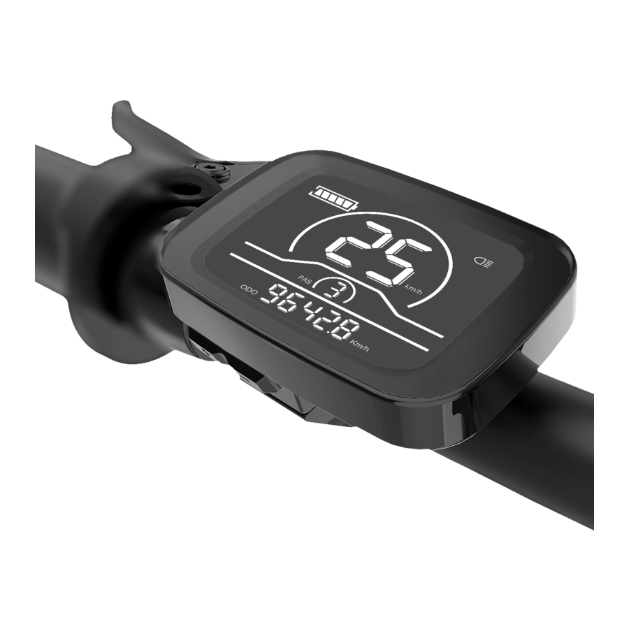
Intelligent LCD display for e-bike; model: YL81C.
- 36V/48V power supply
- Rated working current 15mA
- Maximum working current 30mA
- Leakage current at power-off <1uA
- Working current at the supply controller end 50mA
- Working temperature -20~60
- Storage temperature -30~70
Appearance and dimensions

Function overview and functional area layout
Function overview
Display YL81C provides a variety of functions to meet the riding needs of users, including:
- Battery level indicator
- Assist level adjustment and indication
- Headlight indicator
- Speed indicator (including real-time speed, maximum speed (MAXS) and average speed (AVG))
- Distance indicator (including ODO and trip distance (Trip))
- Error code indicator
- Bluetooth connection indicator (reserved)
- Parameter setting function
Functional area layout

Button definitions
There are three buttons on the operating unit of display YL81C, i.e., the on/off button ![]() , plus button
, plus button ![]() and minus button
and minus button ![]() .
.
General operation
Power on/off
By pressing and holding the button ![]() , the display will start to work and the working power supply of the controller will be turned on. In the power-on state, by pressing and holding the button
, the display will start to work and the working power supply of the controller will be turned on. In the power-on state, by pressing and holding the button ![]() , your e-bike will be powered off. In the power-off state, the display will no longer use the battery power, and its leakage current will be less than 1uA.
, your e-bike will be powered off. In the power-off state, the display will no longer use the battery power, and its leakage current will be less than 1uA.
- If your e-bike is not used for more than 10 minutes, the display will be automatically powered off.
Display interface
After the display is turned on, the display will show the real-time speed (km/h) and the trip distance (km) by default.
By pressing the button ![]() , the information displayed will be switched between the trip distance (km), ODO (km), maximum speed (km/h) and average speed (km/h).
, the information displayed will be switched between the trip distance (km), ODO (km), maximum speed (km/h) and average speed (km/h).
When the distance reaches 9999.9 km, it will be automatically reset to zero.

Push assistance
By pressing and holding the button ![]() , the electric push assistance mode will be enabled. Your e-bike will run at the constant speed of 6km/h. The display will show level P. By releasing the button
, the electric push assistance mode will be enabled. Your e-bike will run at the constant speed of 6km/h. The display will show level P. By releasing the button ![]() , your e-bike will immediately stop power output and return to the state before push assistance.
, your e-bike will immediately stop power output and return to the state before push assistance.

Headlight on/off
By pressing and holding the button ![]() , the controller will turn on the headlights and the display backlight will turn dark. By pressing and holding the button
, the controller will turn on the headlights and the display backlight will turn dark. By pressing and holding the button ![]() again, the controller will turn off the headlights and the display backlight will resumes the luminance.
again, the controller will turn off the headlights and the display backlight will resumes the luminance.

Assist level selection
By pressing the button  , the e-bike assist level will be switched to change the motor output power. The assist levels available for the display include: levels 0-3, levels 1-3, levels 0-5, levels 1-5, levels 0-7, levels 1-7, levels 0-9 and levels 1-9.

Battery level indicator
The battery level indicator consists of five segments. When the battery is fully charged, the five segments will be all on. In case of undervoltage, the outline of the battery indicator will flash, which means the battery has to be charged immediately.

Error code indicator
When a fault occurs in the electronic control system of your e-bike, the display will automatically indicate the error code in the distance area in the format of E0**. Detailed definitions of error codes are shown in Schedule 1.

- When an error code appears on the display interface, please conduct troubleshooting in time. Otherwise, your e-bike will not work normally.
General setting
- All parameters can only be set when your e-bike stops.
The steps for general setting are as follows:
In the power-on state, when the display shows the speed of 0.
Trip distance reset
Press and hold the buttons ![]() and
and ![]() at the same time for more than 2 seconds to reset the trip distance.
at the same time for more than 2 seconds to reset the trip distance.
Factory reset
dEF refers to factory reset. dEF-n represents not to restore factory settings, and dEF-y represents to restore factory settings. Press and hold the buttons ![]() and
and ![]() at the same time for more than 2 seconds to enter the factory reset interface, and press the button
at the same time for more than 2 seconds to enter the factory reset interface, and press the button  to select a parameter.

Custom setting
- All parameters can only be set when your e-bike stops.
The steps for custom setting are as follows:
In the power-on state, when the display shows the speed of 0,- Press and hold the buttons
![]() and
and ![]() at the same time for more than 2 seconds to enter the selection interface of custom setting options;
at the same time for more than 2 seconds to enter the selection interface of custom setting options; - Press the button
![]() to switch the selection interface of general setting options, and press the button
to switch the selection interface of general setting options, and press the button ![]() to enter the parameter modification interface;
to enter the parameter modification interface; - Press the button
![]() for parameter selection;
for parameter selection; ![]() Press the button to save the parameter and return to the selection interface of custom setting options;
Press the button to save the parameter and return to the selection interface of custom setting options;- Press and hold the button
![]() to save the parameter and exit the selection interface of custom setting options.
to save the parameter and exit the selection interface of custom setting options.
- Press and hold the buttons
 to switch the selection interface of general setting options, and press the button
  for parameter selection;
Rated voltage setting
P1 refers to the rated voltage setting option. Available values include: 36V and 48V. Press the button ![]() to enter the parameter modification interface. Press the button
to enter the parameter modification interface. Press the button  for parameter selection. Press the button
 ![]() to save the parameter and return to the selection interface of general setting options.
to save the parameter and return to the selection interface of general setting options.

Wheel diameter setting
P2 refers to the wheel diameter setting option. Available parameters include: 8-32 inches. Press the button ![]() to enter the parameter modification interface. Press the button
to enter the parameter modification interface. Press the button  for parameter selection. Press the button
 ![]() to save the parameter and return to the selection interface of general setting options.
to save the parameter and return to the selection interface of general setting options.

Speed limit setting
P3 represents the speed limit setting option. The adjustable range is 10~40km/h. Press the button ![]() to enter the parameter modification interface. Press the button
to enter the parameter modification interface. Press the button  for parameter selection. Press the button
 ![]() to save the parameter and return to the selection interface of general setting options.
to save the parameter and return to the selection interface of general setting options.

Metric/imperial system setting
P4 refers to the metric/imperial system setting option. 00 represents the metric system, and 01 represents the imperial system. Press the button ![]() to enter the parameter modification interface. Press the button
to enter the parameter modification interface. Press the button  for parameter selection. Press the button
 ![]() to save the parameter and return to the selection interface of general setting options.
to save the parameter and return to the selection interface of general setting options.

Speed sensor setting
P5 refers to the speed sensor setting option, which can be set according to the number of magnetic heads installed on the wheels of your e-bike. The setting range is 1-63. Press the button ![]() to enter the parameter modification interface.
to enter the parameter modification interface.
Press the button  for parameter selection. Press the button
 ![]() to save the parameter and return to the selection interface of general setting options.
to save the parameter and return to the selection interface of general setting options.

Current limit setting
P6 refers to current limit setting. The adjustable range is 1-25A. Press the button ![]() to enter the parameter modification interface. Press the button
to enter the parameter modification interface. Press the button  for parameter selection. Press the button
 ![]() to save the parameter and return to the selection interface of general setting options.
to save the parameter and return to the selection interface of general setting options.

Assistance sensor setting
P7 refers to the assistance sensor setting option, where the number of steel magnets of the assistance magnetic disk can be set. The adjustable range is 5, 6, 7, 8, 9, 10 and 12. Press the button ![]() to enter the parameter modification interface.
to enter the parameter modification interface.
Press the button for parameter selection. Press the button ![]() to save the parameter and return to the selection interface of general setting options.
to save the parameter and return to the selection interface of general setting options.

Power-on password setting
P8 refers to the power-on password setting option. PSd-Y means that a power-on password is required, and PSd-N means that no power-on passwords are required. The default value of the display is PSd-N. Press the button ![]() to enter the modification interface, and press the button
to enter the modification interface, and press the button  to enter the selection interface.
If PSd-N is selected, press the button ![]() to return to the selection interface of custom setting options;
to return to the selection interface of custom setting options;
If PSd-Y is selected, press the button ![]() to enter the password setting interface. If you don t want to change the password, press and hold the button
to enter the password setting interface. If you don t want to change the password, press and hold the button ![]() to exit the custom setting interface. If you want to change the password, press the button
to exit the custom setting interface. If you want to change the password, press the button ![]() for cursor movement and the button
for cursor movement and the button  for figure selection, and then press the button
 ![]() to return to the selection interface of custom setting options.
to return to the selection interface of custom setting options.

Quality commitments and warranty scope
Warranty information
- For the faults caused by the quality of the product under normal use, the Company will be responsible for providing limited warranty during the warranty period.
- The warranty period of the product is within 12 months from delivery.
Non-warranty scope
- The enclosure is opened
- The connector is damaged
- The enclosure is scratched or damaged after delivery
- The outgoing line of the display is scratched or broken
- Faults or damage caused by force majeure (such as fires, earthquakes, etc.) or natural disasters (such as lightning strikes, etc.)
- The warranty period has expired
Outgoing line connection diagram
Wiring sequence of standard connector

Wiring Sequence of Standard Connector
| Standard wiring sequence | Standard wire color | Function |
| 1 | Red (VCC) | Power cord of display |
| 2 | Blue (Kp) | Power control line of controller |
| 3 | Black (GND) | Ground wire of display |
| 4 | Green (RX) | Data receiving line of display |
| 5 | Yellow (TX) | Data transmission line of display |
- The outgoing lines of some products adopt waterproof connectors, and users cannot see the outgoing line color inside the wire harnesses.
Considerations
Please use safely, and do not plug or unplug the display when it is powered on.
- Please avoid bumping as far as possible.
- Please do not alter the background parameter settings of the display at will, otherwise normal riding cannot be guaranteed.
- If the display fails to work normally, it should be repaired as soon as possible.
- Due to product upgrades of the Company, part of the displayed contents or functions of the product you bought may be different from the manual, depending on the actual model.
Error Code Definitions
| Error codes for protocols YL-01 and YL-02: | |||
| Error codes | Definition | Error codes | Definition |
| E001for | Controller Abnormality | E004 | Throttle Abnormality |
| E002 | Communication Abnormality | E005 | Brake Abnormality |
| E003 | Motor Hall Signal Abnormality | E006 | Motor Phase Abnormality |
| Error codes for protocols YL-05, KDS and YL-J: | |||
| Error codes | Definition | Error codes | Definition |
| E021for | Current Abnormality | E024 | Motor Hall Signal Abnormality |
| E022 | Throttle Abnormality | E025 | Brake Abnormality |
| E023 | Motor Phase Abnormality | E030 | Communication Abnormality |
Tel: 022-86838795
Fax: 022-86838795
Email: yolin@yolintech.com
Website: www.yolintech.com
Address: Plant 52-1, Yougu Xinke Park, East of Jingfu Road, Pharmaceuticals and Medical Equipment Industrial Park, Beichen
Economic Development Zone, Beichen District, Tianjin

Documents / Resources
References

Download manual
Here you can download full pdf version of manual, it may contain additional safety instructions, warranty information, FCC rules, etc.
Advertisement
Thank you! Your question has been received!


Need Assistance?
Do you have a question about the YL81C-B that isn't answered in the manual? Leave your question here.