Bosch ISW-ZPR1-WP13 - Wireless PIR Motion Detector Manual
- Installation manual (2 pages)
Advertisement
Overview
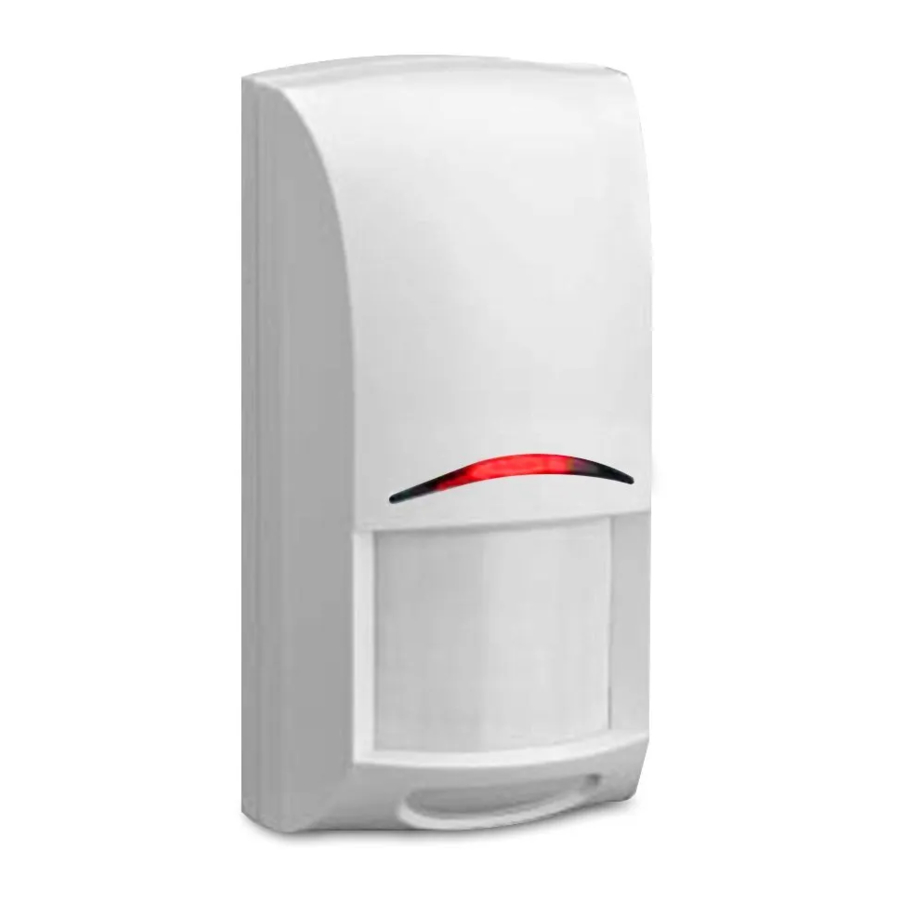
The ISW-ZPR1-WP13 is a wireless PIR motion detector.

Callout ― Description
- Ceiling mount bracket holes
- Surface mount holes
- Wall mount bracket holes
- Cam lock
- Wall tamper hole
- Corner mount holes
- Battery compartments
- Tamper switch
- Look-down tab
Installation considerations
Point away from:
- Direct and indirect sunlight
- Glass exposed to the outdoors
- Objects that may change temperature rapidly such as heat sources or air conditioning outlets
Do not install:
- Near objects that can block the field of-view
- Near direct hot or cold drafts
- In areas with high humidity
Do install:
- On solid, vibration free surface
- Within recommended mounting height range measured from the floor
- Where an intruder is most likely to cross through the coverage pattern
Pet immunity:
- 1 pet up to 31 lbs (14kg)
Notice:
- For indoor use only
- Use of a bracket may reduce range and increase dead zone areas
- PIR technology won't detect through glass
Installation
Open the detector and mount the base to either a flat surface, a corner, or a bracket. The wall tamper option is available for flat surface mounting only.
Opening the detector:
- Turn the cam lock at the bottom of the detector to the open position.
- Hold the base and slide the unit body down to remove it from the base.
Mounting the base:
- Identify the mounting surface; flat or corner. Determine if an optional mounting bracket is needed. Compatible brackets include the B328, B335 and B338. Optional mounting brackets are sold separately.
- Identify which mounting holes to use based on the mounting surface. Refer to Figure 1.1.
- Break away the appropriate mounting hole coverings in the base and install the base of the detector to the surface with screws.
Enabling the look-down:
- Locate the removable tab on the detector body directly below the battery compartments.
- For Pet Immunity, leave the tab intact. If Pet Immunity is not desired, enable the look-down zone. To enable the lookdown zone, pull the tab and remove it completely. Refer to Figure 1.1.
Installing the batteries:
The batteries are not installed in the detector when it is shipped.
- Insert the batteries with the ribbon underneath to ensure easy removal in the future.
- Observe proper polarity when installing the batteries or the sensor will not function. Refer to the diagram on the detector body located between the battery chambers.
Mounting the detector:
Slide the detector body onto the base. Do not lock the bottom of the detector at this time.
Pair the detector
When the batteries are installed, the unit immediately begins to power up.
- The LED lights for two seconds, then the detector enters pairing mode.
- The LED flashes three times every fi ve seconds until the controller discovers the detector. Complete the remaining steps within three minutes to limit battery consumption.
- As soon as the detector enters pairing mode, go to the controller and complete the pairing process according to the controller manufacturer's instructions.
 NOTICE!
If the controller does not discover the detector within three minutes, the detector exits pairing mode and restarts when motion is detected again.
Walk test the detector
To start walk test mode, slide the detector off of the base, then slide it back on.
Performing the walk test:
- Once started, the detector remains in walk test mode for 90 seconds. Begin walk testing during this time. The 90 second timer restarts each time the sensor detects motion during the walk test.
- Once the walk test completes, do not disturb the detector's coverage pattern for 80 seconds.
- After 80 seconds, the detector flashes to indicate the walk test time is about to expire.
- After flashing for 10 seconds, the detector exits walk test mode.
Complete the set up:
When the installation and testing are complete, twist the lock at the bottom of the detector to the closed position.
Operation and maintenance
In the normal operating mode, an alarm is transmitted only after three minutes have passed since the previous alarm restoral. This three minute lockout time reduces unnecessary RF transmissions in high traffic areas thereby extending battery life.
Low battery
If the controller shows a trouble condition it could be the result of low batteries. To trouble-shoot the condition, begin by replacing the batteries.
Opening the detector:
- Turn the cam lock at the bottom of the detector to the open position.
- Hold the base and slide the unit body down to remove it from the base.
Changing the batteries:
- Lift the ribbon to remove all batteries and replace with four new 1.5 V AA batteries.
- Insert the batteries with the ribbon underneath to ensure easy removal in the future.
- Observe proper polarity when installing the batteries or the sensor will not function. Refer to the diagram on the detector body located between the battery chambers.
Replacing the detector:
- Slide the detector body back on to the base. Do not lock the detector at this time.
- The LED starts fl ashing and enters warm up. The sensor requires a 5 second period of inactivity to stabilize. The LED stops fl ashing when the detector is ready to test.
- After the sensor stabilizes, it automatically enters walk test mode. Complete all steps in Section "Walk test the detector".
Detector reset
To reset the detector and return settings to factory default, unlock and open the detector then follow the steps below:
- Remove only the top battery from each of the battery compartments.
- Press and hold the tamper switch.
- Reinsert the batteries in the following order: battery on the right side first, battery on the left side second.
- Release the tamper switch within four seconds after the batteries are reinserted.
- Slide the detector body onto the base. Do not lock the detector at this time.
- Repeat sections "Pair the detector" and "Walk test the detector" completely.
Specifications
| Dimensions | 2.4 in x 4.8 in x 2.1 in (61 mm x 122 mm x 53 mm) |
| Batteries | 6 V (4 x 1.5 V ) Alkaline: Duracell MN1500 AA or Panasonic AM-3PIX AA |
| Operating temperature | +32°F to +120°F (0°C to +49°C) |
| Non-condensing humidity | 0% to 93% |
| Mounting height | 7.5 ft to 9 ft (2.2 m to 2.7 m) |

Bosch Security Systems, Inc.
130 Perinton Parkway
Fairport, NY 14450
USA
Bosch Sicherheitssysteme GmbH
Robert-Bosch-Ring 5
85630 Grasbrunn
Germany

Documents / Resources
References
Download manual
Here you can download full pdf version of manual, it may contain additional safety instructions, warranty information, FCC rules, etc.
Download Bosch ISW-ZPR1-WP13 - Wireless PIR Motion Detector Manual
Advertisement
Thank you! Your question has been received!


Need Assistance?
Do you have a question about the ISW-ZPR1-WP13 that isn't answered in the manual? Leave your question here.