Advertisement
Available languages
Available languages
Table of Contents
- 1 Control Functions
- 2 Mower Deck Removal/Installation
- 3 Clean Deck/Check/Replace Mower Blades
- 4 Check/Change Engine Oil/Filter
- 5 SERVICE Air FILTER PRE-CLEANER
- 6 Replace Air Filter
- 7 Replace Spark Plug/Fuel Filter
- 8 Mower Deck Leveling Adjustments
- 9 Mower Belt Replacement
- 10 Parts Lists
- Download this manual
Operator's Manual
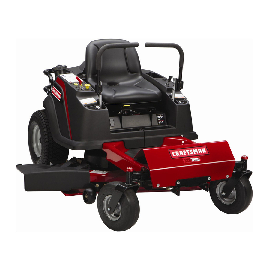
ZT 7000
Zero-Turn Rear Engine Rider
18 HP, 50" Mower
Electric Start
Model No.
107.277700
CAUTION:
Before using this product,
read
the manual and follow all its Safety Rules
and Operating
Instructions,
For answers to your questions
about this
product, call:
1-800-659-5917
Sears Craftsman
Help Line
5 am - 5 pm, Mon - Sat
Nota: Una traducci6n
en espaSol
de este Manual
del Operador
puede encontrarse
en la pAgina
33.
Sears, Roebuck and Co., Hoffman Estates, IL 60179
U.S.A.
Visit our Craftsman website: www.sears.com/craftsman
TP 199-3928-07-CZ-C
1726431-07
Advertisement
Table of Contents

Related Manuals for Craftsman ZT 7000 107.2777


Summary of Contents for Craftsman ZT 7000 107.2777
- Page 1 CAUTION: Before using this product, the manual and follow all its Safety Rules and Operating Instructions, Sears, Roebuck and Co., Hoffman Estates, IL 60179 Visit our Craftsman website: www.sears.com/craftsman For answers to your questions read product, call: 1-800-659-5917 Sears Craftsman...
- Page 2 For your convenience, IN HOME warranty service will still be available after the first 30 days of purchase, but a trip charge will apply. This charge will be waived if the Craftsman product is dropped off at an authorized Sears loca- tion.
- Page 3 Read thesesafety rulesandfollow themclosely. F ailure toobeytheserulescouldresult i n lossofcontrol of unit,severe personal injury or deathtoyou,or bystanders, or damage toproperty or equipment. This mowing deck is capable of amputating hands and feet and throwin og_bjb'ects. The triangle _ in text signifies important cautions or warnings which must be followed. GENERAL OPERATION t.
- Page 4 SLOPE OPERATION Slopes are a major factor related to loss-of-control and tip- over accidents, which can result in severe injury or death. Operation on all slopes requires extra caution, if you cannot back up the slope or if you feel uneasy on it, do not operate on it.
- Page 5 SERVICE AND MAINTENANCE Safe Handling of Gasoline 1. Extinguish all cigarettes, cigars, pipes, and other sources of ignition. 2. Use only approved gasoline containers. 3. Never remove the gas cap or add fuel with the engine running. Allow the engine to cool before refueling. 4.
- Page 6 SAFETY & OPERATION This unit has been designed and manufactured to pro- vide you with the safety and reliability you would expect from an industry leader in outdoor power equipment manufacturing. Although reading this manual and the safety instructions it contains will provide you with the necessary basic knowledge to operate this equipment safely and effec- tively, we have placed several safety labels on the unit to remind you of this important information while you are...
- Page 7 The identification tag is located on the underside of the seat deck. Tilt the seat deck forward to access the ID tag. For answers to your questions about this product, call: 1-800-659-5917 Sears Craftsman Help Line, 5 am - 5 pm, Monday-Saturday. Model Description Name/Number Stock Number...
- Page 8 - Twin Bag Grass Catcher - Headlight • Bumper • Wheel Weights Setup instructions - English Setup in 6 E_y Step: Troubleshooting Keys Setup instructions - Operator's Spanish Book - English/Spanish Oper_toCsManu_l Setup i_, _ _asv Step_: Z_ 7OOO ,,=_ _, _ri, 2._ _2:_:_ s._ _2_)_u_ Troubleshooting...
- Page 9 Read The Operator's Manual • Read the operator's manual. You should always read and follow the instructions in the Operator's manual. Proper care, performance tips, and safety information is located in this important document. Always Check the Oil Level Check the engine oil level. The engine in your tractor has been shipped, from the factory, already filled with 10W-30 weight oil for use during the engine...
-
Page 10: Control Functions
Speed Lever _Left Ground Ground Speed Levers - Ground Speed Levers - DRIVE Positons PARK Positons CONTROL FUNCTIONS The information below briefly describes the function of individual controls. Starting, stopping, driving, and mowing require the combined use of several controls applied in specific sequences. To learn what combination and sequence of controls to use for various tasks please read the entire section. - Page 11 Mower Height of Cut Adjustment To adjust cutting height, rotate the turn crank clockwise to raise the mower deck and counterclockwise the mower deck. ignition Switch The ignition switch starts and stops the engine; it has three positions: Stops the engine and shuts off the electrical system.
- Page 12 CHECKS BEFORE STARTING • Check that the crankcase oil is filled to full mark on dipstick. • Adjust the seat position and make certain you can reach all controls. Fill the fuel tank with fresh fuel. FUEL RECOMMENDATIONS For daily operation: Use only unleaded gasoline with a pump sticker octane rating of 87 or higher.
- Page 13 EMERGENCY STOPPING In the event of an emergency the engine can be stopped by simply turning the ignition switch to STOR Use this method only in emergency situations. shut down follow the procedure given in STOPPING THE RIDER AND ENGINE. STOPPING THE RIDER &...
- Page 14 DRiViNG PRACTICE- BASIC DRIVING WARNING: Never operate on slopes greater than 17.6% (10°). See SLOPE OPERATION in the safety section. Zero turn riders operate differently from other bur- wheeled vehicles. The drive wheels are also your steer- ing wheels. If you cannot drive the unit on a hill, you will not be able to steer the unit on it.
- Page 15 Practice Turning Around a Corner While traveling forward allow one handle to gradually return back toward neutral. Practice several times before mowing. NOTE." To prevent piveting directly on the tire tread, it is best to keep both wheels going at least slightly forward. Executing Turns Figure 7.
-
Page 16: Mower Deck Removal/Installation
MOWER DECK REMOVAL INSTALLATION NOTE: Perform mower removal and installation on a hard, level surface such as a concrete floor. WARNING Engage parking brake, disengage PTO, stop engine and remove key before attempting install or remove the mower. Removing Mower Deck 1. - Page 17 MAINTENANCE SCHEDULE The following schedule should be followed for normal care of your rider and mower. You will need to keep a record of your operating time. Determining operating time is easily accomplished by observing the elapsed time recorded by the hour meter.
- Page 18 Rider Maintenance CLEAN DEBRIS FROM RIDER AND ENGINE COMPARTMENT Service IntervaJ: Before each use. CAUTION: if debris is not removed from the engine compartment and other hot surfaces, it creates a fire hazard. Before starting the unit at the beginning of the mowing session, remove any grass clippings, dirt, leaves, or other debris from the unit.
- Page 19 LUBRiCATiON Service Interval: 25 hours. Lubricate the unit at the locations shown in Figures 15 through 17 as well as the following lubrication points. Grease: • front wheel bushings • mower pivots . front wheel grease fittings • mower arbors Use grease fittings when present.
-
Page 20: Clean Deck/Check/Replace Mower Blades
CLEAN DECK & CHECK / REPLACE MOWER BLADES Service Intervah 25 hours or as required. WARNING For your personal safety, do not handle the sharp mower blades with bare hands. Careless or improper handling of blades may result in serious injury. - Page 21 CLEANING THE BATTERY AND CABLES WARNING Be careful when handling the battery. Avoid spilling electrolyte. Keep flames and sparks away from the battery. When removing or installing battery cables, disconnect the negative cable FIRST and reconnect it LAST. if not done in this order, the positive terminal can be shorted to the frame by a tool.
- Page 22 CHECK / ADJUST PTO CLUTCH • ILWARNING To avoid serious injury, perform adjustments with engine stopped, key removed and tractor on level ground. Service interval: 200 Hours. The PTO clutch is engaged and disengaged by the PTO switch. The clutch powers and brakes the mower blades. Check the PTO clutch adjustment every 200 hours of operation.
-
Page 23: Check/Change Engine Oil/Filter
Engine Maintenance CHECK ENGINE OIL LEVEL Service Interval: Before each use, and every 8 hours. 1. Turn the engine off, and set the parking brake to PARK. 2. Clean the area around the dip stick (C, Figure 25). Remove the dip stick (C) and clean it with a paper towel. -
Page 24: Service Air Filter Pre-Cleaner
SERVICE AiR FILTER PRE-CLEANER Service Interval: 25 Hours or as required. 1. Loosen the air filter cover knob and remove the cover (A, Figure 26). Clean out any debris from around the air filter. Inspect the condition of the sealing surfaces of the air filter element (D) and filter base. -
Page 25: Replace Spark Plug/Fuel Filter
REPLACE SPARK PLUG Service Interval: 200 Hours. Replacement Spark Plug: Champion RC12YC or equiv- alent Spark Plug Gap: .040" (lmm) 1. Stop the engine and allow it to cool. 2. Clean the area around the spark plug (A, Figure 28). 3. - Page 26 Figure 29. Seat Adjustment A. Seat Adjustment Knob (Underside of Seat Deck) SEAT ADJUSTMENTS The seat and ground speed control levers should be adjusted so the ground speed control levers can be moved through their full range of motion. The seat can be adjusted forward and back. Loosen the adjustment knob (A, Figure 29) located on the underside of the seat deck, move the seat to the desired position, then tighten the knob.
- Page 27 CUTTING HEIGHT ADJUSTMENT Turn the cutting height adjustment crank (A, Figure 31) clockwise to raise the mower deck and counterclockwise to lower it. If the crank is difficult to turn, thoroughly clean and lubricate it. PTO CLUTCH ADJUSTMENT See CHECK / ADJUST PTO CLUTCH in the Maintenance Section.
-
Page 28: Mower Deck Leveling Adjustments
MOWER DECK LEVELING ADJUSTMENTS WARNING Before checking mower, shut off PTO and engine. Allow all moving parts to stop. Remove ignition key, then disconnect the spark plug wire and fasten it away from the spark plug. If the cut is uneven, the mower may need leveling. Unequal or improper tire pressure may also cause an uneven cut. -
Page 29: Mower Belt Replacement
Figure 36. Orient Blades Front-to-Back Front To Back Leveling 1. Turn the blades front-to-back as shown in Figure 36. Measure the distance from the ground to front tip of center blade, and from ground to rear tips of left hand and right hand blades (Figures 33 &... - Page 30 STO RAG E Before you store your unit for the off-season, read the Maintenance and Storage instructions in the Safety Rules section, then perform the following steps: • Disengage the PTO, set the parking brake, & remove the key. Check all fluid levels. Check all maintenance items. •...
- Page 31 While normal care and regular maintenance will extend the life of your equipment, prolonged or constant use may eventually require that service be performed to allow it to continue operat- ing properly. The troubleshooting guide below lists the most common problems, their causes and remedies. If you prefer, all of these procedures can be performed for you by a Sears Parts &...
- Page 32 Engine Transmission release levers in PUSH runs, but rider will not 9ositions. drive. Drive belt slips. Belt is broken. Parking brake is not fully released. Rider drive belt Pulleys or belt greasy or oily. slips. Belt stretched or worn. Parking brake Parking brake is incorrectly adjusted.
- Page 33 Para obtener respuestas sobre este producto, diferente- fono-(sin cobro) siguiente: 1-800-659-5917 Servicio de ayuda Sears Craftsman 5 am - 5 pro, Lunes a Sabado a qualquier pregunta Ilame al num6ro de tel&...
- Page 34 GARANTIA LIMITADA DEL EQUIPO MONTABLE DE CRAFTSMAN Pot dos (2) aOos a partir de la fecha de compra, si este equipo montable de Craftsman es mantenido, lubricado y afinado conforme alas instrucciones en el manual del propietario, Sears repararb, o reemplazarb, sin costo alguno cualquier parte que se encuentre defectuosa en material o mano de obra conforme a los lineamientos de la cobertura enumerada a contin- uaciOn.
- Page 35 Lea estas reglas de seguridad y sigalas con cuidado. No obedecer estas reglas puede resultar en la perdida del control sobre la unidad, lesiones severas a la persona o la muerte de usted o espectadores, o dahos a la propiedad o al equipo. Esta cubierta de la podadora es capaz de amputar El trib,ngulo...
- Page 36 OPERACION EN CUESTAS Las cuestas son un factor importante relacionado con los acci- dentes pot perdida de control y volcaduras, Io cual puede resultar en lesiones severas o la muerte. Cualquier operaci6n en cuestas exige precauciones extremas. Si usted no puede dar marcha atrAs en una cuesta o se siente inquieto en ella, no opere en ella.
- Page 37 SERV]C]O Y MANTENilVI[ENTO Manejo Seguro de la Gasolina 1. Apague todos los cigarros, puros, pipas y otras fuentes de ignicion. 2. Use solo los contenedores aprobados para gasolina. 3. Nunca quite el tapon de la gasolina ni ponga combustible con el motor encendido. Permita que el motor se enfrie antes de poner combustible.
- Page 38 CALCOMANiAS DE SEGURIDADY OPERACION Esta unidad fue diseSaday fabricada para ofrecerle la seguridad y confiabilidad que usted esperarfa de un Nder en la indus- tria de la fabricacidn de equipos motorizados para el exterior. Aunque leer este manual y las medidas de seguridad que contiene le proporcionara, el conocimiento ba.sico necesario para operar este equipo sin percances y eficazmente, hemos colocado varias etiquetas de seguridad en la unidad para...
- Page 39 Para obtener respuestas a sus preguntas sobre el pro- ducto, Ilame ah 1-800-659-5917 Servicio Telef6nico de Asistencia de Sears Craftsman, 5 am - 5 pm, Lunes - Sgtbado. o infor= Nombre/Numero de Descripci6n del Modelo...
- Page 40 - Recolector de Hierba con Bolsa - Faro delantero Instrucciones Disposici6n - Ingles Setup in 6 E_y _tep: Troubleshooting Llaves Gemela Instrucciones Disposici6n - EspaSol Setup ,,=_ _, 2._ _2:_:_ s._ _2_)_u_ Troubleshooting O_l_Wt_'s MANU_L Cot_t_D SER_S CW_ C_, _W_, CV_, CW_,CW_, Manual del Motor IVlanual del Operador y Libro de...
- Page 41 Leer el Manual Operador Usted siempre debe leer y seguir las instrucciones en el manual del Operador. En este importante docu- mento encuentra informaci6n sobre el debido cuidado, consejos de rendimiento y seguri- dad. Siempre Verificar el Nivel del Aceite El motor en su tractor fue embarca- do, de fabrica, Ileno con aceite 10W- 30 de peso para usar durante el...
- Page 42 Velocidad Izquierda Palanca de Perilla de Ajuste del Asiento Tapdn del Tanque de Gaeolina Palancas de Velocidad Palancas de Velocidad - - Posici6n de DRIVE - Posici6n de PARK FUNClONES DE CONTROL La informaci6n abajo describe brevemente la funci6n de los controles individuales. Arrancar, detenerse, conducir y podar el c6sped requiere del uso combinado de vafios controles aplicados en secuencias especificas.
- Page 43 Ajuste de AJtura de Corte Para ajustar la altura de corte, gire la manivela a la derecha para subir la cubierta de la podadora y a la izquierda para bajar la cubierta de la podadora. Interrupter de Encendido El interrupter de encendido arranca y detiene el motor; tiene tres posiciones: OFF (apagado) Detiene el motor y corta el sistema el6ctrico.
- Page 44 VERIFICACIONES ANTES DE ARRANCAR • Verifique que el aceite del cb,rter est6 en la marca de Ileno de la varilla de nivel de aceite. • Ajuste la posici6n del asiento y cerci6rese de poder alcanzar todos los controles. • Llene el tanque de gasolina con combustible fresco. RECOMENDACIONES DE COMBUSTIBLE Para operaciSn diaria:...
- Page 45 PARO DE EMERGENCIA En el caso de una emergencia, el motor puede detenerse simplemente girando el interruptor de encendido a STOR Use este metodo s61o en situaciones de emergencia. Para apagar el motor normalmente, sJga el procedimien- to dado en DETENER EL TRACTOR Y EL MOTOR. DETENER EL TRACTOR Y EL MOTOR 1.
- Page 46 PR. ,CTICA DE IVIANEJO - MANEJO BASlCO ADVERTENClA: Nunca opere en cuestas mayoras a 17.6% (10°). Vea OPERACION EN CUESTAS en la secci6n de seguridad. Los tractores de giro cero operan de modo difer- ente a otros vehiculos de cuatro ruedas. Las ruedas de trac- ci6n tambien son sus ruedas de direcci6n.
- Page 47 Prbctica de dar Vuelta en una Esquina Mientras viaja hacia adelante permita que una palanca regrese gradualmente en direcci6n del neutral. Practique varias veces antes de podar el cesped. NOTA: Para evitar girar directamente sobre la banda de rodamiento, es mejor mantener /as dos ruedas en mar- cha hacia adelante aunque sea ligeramente.
- Page 48 REMOCION E INSTALACION CUBIERTA DE LA PODADORA NOTA:Ejecute la remocidn e instalacidn de la podadora sobre una supefficie dura y nivelada como un piso de concreto. ADVERTENCIA Accione el freno de mano, desacople detenga el motor y quite la llave antes de intentar instalar o quitar la podadora.
- Page 49 PROGRAIVIA DE MANTENllVilENTO El siguiente programa debe seguirse para el cuidado normal de su tractor y podadora. Serb, necesario que mantenga un registro de su tiempo de operaci6n. transcurrido en el medidor de horas. ELEMENTOS DE MANTENI= MIENTO DELTRACTOR Limpiar despojos del tractor y del com- partimiento del motor * Limpiar despojos del area de enfriamien- to del motor y del filtro de aire *...
- Page 50 Elementos de Mantenirniento del Tractor LIMPIAR DESPOJOS DEL TRACTOR Y DEL COMPARTIMIENTO DEL MOTOR Intervalo de Servicio: Antes de cada uso. PRECAUCION: Si no se quitan los despojos del com- partimiento del motor y otras superficies calientes, se crea un peligro de incendio. unidad al inicio de la sesi6n de podado de c_sped, elim- ine cualquier hierba cortada, mugre, hojas u otros despojos de la unidad.
- Page 51 LUBRICACION Intervalo de Servicio: 25 horas. Lubrique la unidad en los lugares mostrados en las Figuras 15 a 17 asi como en los siguientes puntos de lubricaci6n. Grasa: • engrasadores de la rueda delantera • bujes de la rueda delantera •...
- Page 52 LilVlPIAR CUBIERTAY VERIFICAR/ REEMPLAZAR ASPAS DE PODADORA Intervalo de Servicio: 25 horas o segQn se requiera. ADVERTENCIA Para su seguridad personal, no maneje las aspas afHadas de la podadora con las manos descubiertas. El manejo imprudente de las aspas puede resuitar en lesiones ADVERTENCIA Para su seguridad personal, los tornillos de cabeza hexagonal...
- Page 53 LIMPIAR BATERiAY CABLES ADVERTENCIA Tenga cuidado al manejar la bateda. Evite derramar el electrolito. Mantenga chispas lejos de la bateria. Cuando quite o instale los cables de la bateria, desconecte PRIMERO el cable negativo y con_ctelo al ULTIMO. Si no se hace en este orden, la terminal causar un cortocircuito al bastidor...
- Page 54 VERIFICAR/AJUSTAR EMBRAGUE DEL PTO ADVERTENCIA Para evitar lesiones graves, s61o haga los ajustes con el motor detenido, la Ilave quitada y el tractor en terreno niveiado. Intervalo de Servicio: 200 horas. El embrague del PTO se embraga y desembraga con el interruptor PTO.
- Page 55 Elementos de Mantenirniento del Motor VERIFICAR NIVEL DE ACEITE DEL MOTOR Intervalo de Servicio: Antes de cada uso y cada 8 horas. 1. Apague el motor y ponga el freno de mano en PARK. 2. Limpie el b.rea alrededor de la varilla de nivel de aceite (C, Figura 25).
- Page 56 DAR SERVlCIO AL PRE-LIIVlPIADOR FILTRO DE AIRE Intervalo de Servicio: 25 horas o segOn se requiera. 1. Afloje la perilla de la tapa del filtro de aire y quite la tapa (A, Figura 26). Limpie cualquier suciedad en el interior y alrededor del filtro de aire. Inspeccione la condici6n de las superficies selladas del elemento del filtro de aire (D) y la base del filtro.
- Page 57 REEIVIPLAZAR BUJiA IntervaJo de Servicio: 200 horas. Bujia de Repuesto: Champion RC12YC Entrehierro de Bujia: .040" (1ram) 1. Detenga el motor y permita que se enfrfe. 2. Limpie el Area alrededor de la bujia (A, Figura 28). 3. Quite la bujia e inspecci6nela. gastada, reempl_.cela.
- Page 58 Figura 29. Ajuste del Asiento Perilla de Ajuste del Asiento (Abajo del Asiento) AJUSTES AL ASIENTO El asiento y las palancas del control de velocidad deben estar ajustados de modo que las palancas del control de velocidad puedan moverse pot el arco completo de movilidad.
- Page 59 AJUSTE DE LA ALTURA DE CORTE Gire la manivela del ajuste de la altura de corte (A, Figura 31) a la derecha para subir la cubierta de la podadora y a la izquierda para bajarla. Si se le dificulta girar la manivela, limpiela bien y lubriquela. AJUSTE DEL EMBRAGUE Vea VERIFICAR/AJUSTAR...
- Page 60 AJUSTE DE NIVEL DE LA CUBIERTA DE LA PODADORA ADVERTENCIA Antes de verificar la podadora, apague el PTO y el motor. Permita que se detengan todas las partes en movimiento. Quite la llave del encendido, luego desconecte el cable de la bujia y suj_telo lejos de la bujia.
- Page 61 Figura 36. Orientar las Aspas de Adelante hacia Atrbs Nivelado de Adelante hacia Atr_s 1. Gire las aspas de adelante hacia atrb, s como se muestra en la Figura 38. Mida la distancia delantera del aspa central, y del suelo a la punta trasera de las aspas izquierda y derecha (Figuras 33 y 38).
- Page 62 ALMACENAMIENTO Antes de almacenar su unidad en la temporada instrucciones de Mantenimiento y Almacenamiento ci6n de Reglas de Seguridad, luego realice los siguientes pasos: ,, Desacople el PTO, ponga el freno de mano y quite la Ilave. Verifique el nivel de todos los fiuidos. Verifique todos los elementos de mantenimiento.
- Page 63 Si bien el cuidado normal y el mantenimiento derAn la vida de su equipo, el uso prolongado o constante hath, que eventualmente se deba realizar un servicio para permitir que contint]e operando debidamente. abajo enumera los problemas mAs comunes, sus causas y remedios.
- Page 64 El motoropera Laspalancas d edesembrague de la _eroel tractor transmisi6n e nposici6n de EMPUJAR. no avanza. Labandadetracci6n sebarre. LabandaestArota. Freno demanonoestAdesaccionadoContacte Partes y Reparaciones deSears. Bandadetrac- Poleas o labanda congrasao aceite. Limpie segQn se requiera. ci6n se barre. La banda esta estirada o desgastada. El freno de mano El freno de mano esta mal ajustado.
- Page 65 RepairParts PTS - 1...
-
Page 66: Parts Lists
Frame, Body & Seat Group (986460) NOTE: Unless noted otherwise, use the standard hardware torque specification chart, / 85 / 63 Torque Capscrew to 72-77 Ft. Lbs. PTS - 2 ZT 7000 107.277700... - Page 67 Frame, Body & Seat Group REF NO PART NO. QTY. DESCRIPTION 1726018SM SEAT ASSEMBLY, wth Arm Rests (Includes Ref. No. 68) 1726305SM DECK, Seat 1722293SM CAPSCREW, 1726369SM PLATE, Pod Control 1673320SM RIVET, Pop 1708504SM SCREEN, Seat Deck 1960715SM SCREW, Truss Head Torx Drive, 1/4-20 x 3/4 1920397SM NUT, Hex Lock ESNA Light, 1/4-20 1960694SM...
- Page 68 Frame, Body & Seat Group (986460) NOTE: Unless noted otherwise, use the standard hardware torque specification chart, / 85 / 63 Torque Capscrew to 72-77 Ft. Lbs. PTS - 4 ZT 7000 107.277700...
- Page 69 Frame, Body & Seat Group REF NO PART NO, QTY, DESCRIPTION 1960368SM LUG NUT, Speed, 1/4-20 1930641SM NUT, Hex Flange Whiz Lock, 1/4-20 1930644SM NUT, Hex Flange Two-Way Lock, 1/2-13 1709235SM SPACER 1716064ASM HOOK & WASHER ASSEMBLY 1726025A PANEL, Footrest 1726306SM PAD, Footrest, Front 1726504SM...
- Page 70 Engine Group (986461) NOTE: Unless noted otherwise, use the standard hardware torque specification chart. See Engine Manuafacturer service parts. Torque 18 Ft. Lbs. PTS - 6 ZT 7000 107.277700 Tighten Ref. No. 12 external thread into internal thread. Tighten an additional revolutions with a wrench.
- Page 71 Engine Group (986461) DESCRIPTION REF NO PART NO. QTY. 1726398SM CONTROL, Throttle ENGINE, 18HP, KOHLER 1726420SM SEAL, Foam 1927187SM CAPSCREW, 1720463SM KEY, Parallel 1719385SM PULLEY 1686880SM CLUTCH, Electric, OGURA 2832747SM TIE, Self Locking 1708264SM WASHER, Hex 1918199SM LOCKWASHER, 2860631SM CAPSCREW, 1726498SM HOSE, Oil Drain 1713502SM...
- Page 72 Carrier Group (986465) NOTE: Unless noted otherwise, use the standard hardware torque specification chart, Torque Nut to 75 Ft. Lbs. I 26 PTS - 8 ZT 7000 - 107.277700 120 Deg tees to idler anm. Torque Nut 75 Ft. Lbs, t _'_...
- Page 73 Carrier Group (986465) DESCRIPTION REF NO PART NO, QTY, 1726470SM V-BELT 1917372SM NUT, Hex, 5/16-18 1917356SM LOCKWASHER, 1924874SM WASHER, 5/16 1715971ASM ARM, Idler 1713588SM SPACER, Powdered Metal 1928957SM CAPSCREW, 1924940SM WASHER, 3/8 2154534SM PULLEY, Idler 1667812SM SPACER, Powered Metal 1726527SM SPRING, Extension 1665699SM SPACER...
- Page 74 Transmission Group (986462) NOTE: Unless noted otherwise, use the standard hardware torque specification chart. Transmission Seal Kit '-" _" "_'_ " PTS - 10 ZT 7000 107.277700 Torque 15 ft. Ibs. Torque to 50-60 ft. Ibs. line up with castle nut, If cotter pin does not...
- Page 75 Transmission Group (986462) DESCRIPTION REF NO PART NO. QTY. 2833098SM CLAMP, Hose, Wire Type E 1719556SM HOSE, Hydraulic 1701011SM TIE, Self Locking 1960294SM NUT, Hex, Whiz Lock, Flange, 1/4-20 1921319SM WASHER, 1/4 1921959SM CAPSCREW, 1719912SM FILTER, Reservoir 1723164SM WASHER, Special 1719557SM HOSE, Hydraulic 1702488SM...
- Page 76 Transmission Group (986462) NOTE: Unless noted otherwise, use the standard hardware torque specification chart. Transmission Seal Kit '-" _" "_'_ " PTS - 12 ZT 7000 107.277700 Torque 15 ft. Ibs. Torque to 50-60 ft. Ibs. line up with castle nut, If cotter pin does not...
- Page 77 Transmission Group (986462) DESCRIPTION REF NO PART NO. QTY. 1960027SM WASHER, 1/2 1715958SM LINK, Control Rear, R.H. 1931335SM CARRIAGE BOLT, 5/16-18 x 1, G5 1703900SM SPACER 1919438SM NUT, Hex ESNA Light Lock, 5/16-18 1725945SM ROD, Control 1715959SM LINK, Control Rear, L.H. 1921333SM CAPSCREW, 1701011SM...
- Page 78 Controls Group (986463) NOTE: Unless noted otherwise, use the standard hardware torque specification chad. Frame PTS - 14 ZT 7000 107.277700...
- Page 79 Controls Group (986463) DESCRIPTION REF NO PART NO. QTY. 1727049SM BRACKET, Mounting, R.H. 1725978SM BRACKET, Switch 1921977SM CAPSCREW, 1919326SM WASHER, 5/16 1726445SM WASHER, Flat Nylon, 1/2 1710437SM SPACER 1725933SM BRACKET, Tube Mount, R.H. 1725934ASM TUBE, Control Wand 1726410SM GRIP, Foam Handle Bar 1960686SM NUT, Hex Flange ESNA, 5/16-18 1720452SM...
- Page 80 Electrical Group (986464) NOTE: Unless noted otherwise, use the standard hardware torque specification chart. Seat Switch Headlig_i (Optional) Electric Clutch PTS - 16 ZT 7000 107.277700 ToEngine Block on Engine TO Engine...
- Page 81 Electrical Group (986464) DESCRIPTION REF NO PART NO. QTY. 1732006SM SWITCH, Push Button 1686734SM SWITCH ASSEBMLY, 1960547SM LOCKWASHER, 1717549SM NUT, Hex Flange, 5/8-32, Ignition Switch 1717550SM COVER, Ignition Switch 1717163SM KEYS (Set of Two Keys) 1731184SM METER, Hour Digital, with Oil & Lube Alarms 1722611SM PLUG, Hole 1722887SM...
- Page 82 Wheels & Tires Group (W986467) NOTE: Unless noted otherwise, use the standard hardware torque specification chart, 'X.>'... "... •-,".: .< -.. PTS-18 ZT 7000 - 107.277700...
- Page 83 Wheels & Tires Group (W986467) REF NO PART NO. QTY. DESCRIPTION 2860202SM WASHER, 3/4 1716099SM NUT, Hex Lock PAL, 3/4-20 1722675SM CAP, Hub 1726383SM WHEEL & TIRE ASSEMBLY, 2172353SM VALVE STEM & CAP 2177725SM NUT, Hex Lug, 7/16-20 1726382SM WHEEL & TIRE ASSEMBLY, 1713167SM BUSHING, Wheel 2812808SM...
- Page 84 Decals Group (D986467) ZT 7000 - 107.277700 NOTE: Unless noted otherwise, use the standard hardware torque specification chart. PTS - 20...
- Page 85 Sealed Hydraulic System Engine 18HP Kohler Do Not Remove Foam Seal Hood Stripe, L.H. Speed Control, L.H. 18 Model ZT 7000 ZT 7000 Parking Brake CRAFTSMAN Panel Upper, Operation Panel Lower, Warning/Danger & Icon Indicator Tracking Speed Control, R.H. Transmission Release Valve...
- Page 86 50" Mower Deck - Clutch & Support NOTE: Unless noted otherwise, use the standard hardware torque specification chart. ARBOR PULLEY Group (986473) PTO Clutch MOVABLE IDLER PULLEY ARBOR DRIVE PULLEY 27 26 PTS - 22 ZT 7000 107.277700...
- Page 87 50" Mower Deck - Clutch & Support DESCRIPTION REF NO PART NO. QTY. 1726472SM V-BELT, Mower Drive 1726471SM V-BELT, P.T.O. 1960339SM NUT, Hex Flange, 3/8-16 2171247SM PULLEY, Idler 1667811SM SPACER, Powdered Metal 1726814SM LEVER & HANDLE ASSEMBLY 1714062SM SPRING, Extension 1923701SM CAPSCREW, 1922918SM...
- Page 88 50" Mower Deck - Height Adjustment Group (986471) ZT 7000 107.277700 NOTE: Unless noted otherwise, use the standard hardware torque specification chart, 24 21 PTS - 24...
- Page 89 50" Mower Deck - Height Adjustment REF NO PART NO. QTY. DESCRIPTION 1931202SM CAPSCREW, 1919381SM WASHER, 5/16 1704114SM ROD, Indicator Height of Cut 1726424ASM PLATE & BRACKET ASSEMBLY, 1724009SM TRUNNION, 1704097SM WASHER, Detent 2816001SM PIN, Spring 1960170SM WASHER, 9/16 1715892SM TRUNNION, 1704314SM FITTING, Lube...
- Page 90 50" Mower Deck - Housing NOTE: Unless noted otherwise, use the standard hardware torque specification chart. Torque Capscrews to 45-55 Ft. Lbs, or 61-75 NM. & Arbor Group (986468) PTS - 26 ZT 7000 107.277700...
- Page 91 50" Mower Deck - Housing REF NO PART NO. QTY. DESCRIPTION 1714419SM NUT, Hex Flange Non-Locking, 9/16-18 1713675SM WASHER, Belleville 1720387SM PULLEY 1713158SM HUB, Spacer, 2-13/32 1713098SM PULLEY 1713533SM HUB, 35/64 1713197SM HUB, Serated, 35/64 1655729ASM HOUSING, Arbor Top 2108202SM BEARING, Ball 1715724SM SPACER, Bearing Sleeve...
- Page 92 Engine Parts Group 1 Crankshaft Group 3 Oil Pan/Lubrication 0--4 3" Group 4 Head/Valve/Breather PTS - 28 ZT 7000-Model No. 107.277700 Group 2 Crankcase...
- Page 93 Engine Parts REF NO. PART NO. QTY. CRANKSHAFT - Group 1 12 014 57-S Crankshaft (Includes 2) 25 139 27-S Plug, cup CRANKCASE - Group 2 12 032 03-S Seal, crankshaft Crankcase (Use: Short Block 12 522 69) 12 445 02-S Strap, lifting M-839025-S Screw, hex.
- Page 94 Engine Parts Group 5 Ignition/Electrical 20 18j\ _>\18 Group 7 Starting System & ZT 7000 =Model No. 107.277700 Group 6 Blower Housing & Baffles Group 8 Fuel System PTS - 30...
- Page 95 Engine Parts REF NO. PART NO. QTY. IGNITION/ELECTRICAL - Group 5 Screw, hex. flange 12 086 14-S Washer, plain 3/8" 12 468 03-S Retainer, grass screen 24 018 03-S Screen, grass 24 162 03-S Bolt, shoulder 25 086 47-S 12 157 06-S X-42-15-S Flywheel 12 025 15-S...
- Page 96 Engine Parts ZT 7000-Model No. 107.277700 Group 10 Group 9 Air Intake/Filtration Engine Controls e_16 0--5 6 ... Group 11 Exhaust PTS - 32...
- Page 97 Engine Parts REF NO. PART NO. QTY. ENGINE CONTROLS - Group 9 12 079 11-S Linkage, choke 12 237 01-S Clamp, cable M-545016-S Screw, hex. flange M5x0.8x16 M-664020-S Screw, lobed socket M6xl .Ox2O 12 536 01-S Control, speed assembly (includes 6-8) 12 086 39-S Screw, pan hd.
- Page 98 Common Hardware Types Hex Head Capscrew Carriage Bolt Standard Hardware Sizing When a washer or nut is identified as 1/2", Nominal size, meaning the inside diameter is 1/2 inch; if a second number is present it represent the threads per inch When bolt or capscrew is identified as 1,/2 - 16 x 2", this means the Nominal size, or body diameter is 1/2 inch;...
- Page 99 U.S.A. call 1-800-4-MY-HOME@ Acuerdo Felicidades por su compra inteligente. Su nuevo produc- to de Craftsman@ fue dise_ado y fabricado para a_os de operaci6n confiable. Pero come todos los productos, es posible que cada cierto tiempo requiera de reparaciones.
- Page 100 For repair-in your home-of lawn and garden equipment, rio matter who made it, rio matter who sold it! For,the replacement owner s manuals that you need to do-it-yourself. For Sears professional and items like garage door openers and water heaters. 1=800=4=MY=HOME Callanytime, day or night (U.S.A.and Canada) www.sears.com...