Advertisement
Quick Links
INSTALLATION AND MAINTENANCE INSTRUCTIONS
NBG-12WL Wireless Pull Station
SPECIFICATIONS
Maximum Operating Voltage:
Maximum Current Draw:
Average Operating Current:
Maximum Transmit RF Power:
Radio Frequency Range:
Temperature Range:
Humidity:
Battery Type:
Battery Life:
Battery Replacement:
Dimensions:
Accessories:
BEFORE INSTALLING
This pull station must be installed in compliance with the control panel sys-
tem installation manual, the SWIFT Wireless Gateway Manual, applicable
NFPA standards, national and local Fire codes and the requirements of the
AHJ (Authority Having Jurisdiction). Regular testing of the devices should be
done in accordance with the appropriate NFPA standards. Pull stations offer
maximum performance when installed in compliance with the National Fire
Protection Association (NFPA); see NFPA 72.
NOTICE: This manual should be left with the owner/user of this equipment.
GENERAL DESCRIPTION
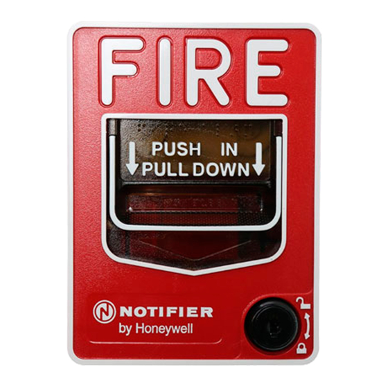
The NBG-12WL wireless, addressable pull station is a UL38-compliant dual-
action manual pull station with a key-lock reset feature intended for use with
a wireless gateway or wireless fire alarm control panel (FACP). (See Figure 1).
It provides NOTIFIER panels one addressable alarm initiating input. The
device communicates through a robust, bi-directional mesh network to the
gateway and/or FACP. Rotary dial switches are provided for setting the pull
station's address. (See Figure 2.) Operating instructions are molded into the
pull station handle along with Braille text. The wireless pull station meets
the Americans with Disabilities Act Accessibility Guidelines (ADAAG) controls
and operating mechanisms guidelines (section 4.1.3[13]), the Americans with
Disabilities Act (ADA) requirement for a 5 lb. maximum pull force to activate
the pull station and conforms to ANSI/UL Standard 38.
Panels offer different feature sets across the various models. As a result, cer-
tain features may be available on some control panels, but not on others. The
possible feature sets available with the wireless pull station include:
• An LED on the wireless pull station is controlled by the panel to indicate
device status. Operational modes include red, green and amber colors in
various solid or blink patterns.
COMPATIBILITY REQUIREMENTS
To ensure proper operation, this module shall be connected to a compatible
Notifier system control panel (list available from Notifier).
FIGURE 1. WIRELESS MANUAL PULL STATION
3.3 VDC
5.0 mA (LED on)
210 µA
17 dBm
902-928 MHz
32°F to 120°F (0°C to 49°C)
10% to 93% Non-condensing
4 Panasonic CR123A or 4 Duracell DL123A
2 year minimum
Upon TROUBLE BATTERY LOW display and/or during annual maintenance
5.6" (142 mm) H x 4.2" (107 mm) W x 2.1" (53 mm) D
Battery Cartridge W-BATCART
C2039-00
BATTERY DOOR
The battery door includes a magnet for activation and tamper resistance. (See
Figure 2.) The battery door magnet activates communication to the panel,
therefore, the battery door must be installed and closed for the pull station
to work properly. The magnet also activates a tamper fault at the panel if the
battery door is opened. Do NOT remove this magnet.
BATTERY REPLACEMENT
Low battery levels on the wireless devices are displayed as a trouble in the
FACP. Therefore when the message "TROUBLE BATTERY LOW" is displayed,
replace the battery in the device. This message is an indication that approxi-
mately one week of battery life remains.
To replace the batteries in a wireless device use the following steps:
1. Have 4 CR123A (or DL123A) batteries available.
2. Use the key to unlock and open the pull station door.
3. Open the battery compartment. (See Figure 2.)
4. Remove the used batteries and replace with new batteries. Batteries can
be inserted directly into the pull station or inserted as a set of 4 batteries
pre-loaded in a battery cartridge available from Notifier. (See Figure 2.) The
battery compartment and cartridge indicate the correct orientation of the
batteries. Carefully align the batteries with these markings, and do not force
them into place.
5. Close the battery compartment cover.
6. Close and lock the pull station door.
FIGURE 2. BATTERY INSTALLATION
Battery Compartment With Door Open
Battery Compartment Door in the Open (Down) Position
Battery Cartridge
1
12 Clintonville Road
Northford, CT 06472-1653
Phone: 203.484.7161
Battery Compartment Door in the Closed (Up) Position
Battery
Magnet
Location
Rotary Address Switches
I56-4266-000
11/06/2017
C2041-00
C2030-00
Advertisement

Related Manuals for Honeywell NOTIFIER NBG-12WL


Summary of Contents for Honeywell NOTIFIER NBG-12WL
- Page 1 INSTALLATION AND MAINTENANCE INSTRUCTIONS 12 Clintonville Road NBG-12WL Wireless Pull Station Northford, CT 06472-1653 Phone: 203.484.7161 SPECIFICATIONS Maximum Operating Voltage: 3.3 VDC Maximum Current Draw: 5.0 mA (LED on) Average Operating Current: 210 µA Maximum Transmit RF Power: 17 dBm Radio Frequency Range: 902-928 MHz Temperature Range:...
- Page 2 LICENSING STATEMENT Use of these products in combination with non-Honeywell products in a wireless mesh network, or to access, monitor or control devices in a wireless mesh nework via the internet or another external wide area network, may require a separate license from Sipco, LLC. For more information, contact Sipco, LLC or Ipco, LLC at 8215 Roswell Rd., Building 900, Suite 950, Atlanta, GA 303350, or at www.sipocollc.com or www.intusiq.com.