
Related Manuals for Husqvarna ST 224P


Summary of Contents for Husqvarna ST 224P
- Page 1 ST 224, ST 227P, ST 230P, ST 224P Default Operator's manual 2-25 ES-MX Manual del usuario 26-51 FR-CA Manuel d’utilisation 52-77...
-
Page 2: Table Of Contents
C C ontents Introduction..............3 Maintenance..............15 Safety................5 Troubleshooting............22 Assembly................ 8 Transportation, storage and disposal......24 Operation..............11 Technical data.............. 25 694 - 002 -... -
Page 3: Introduction
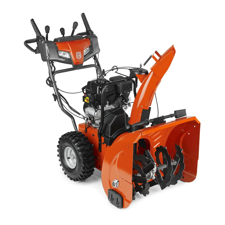
I I ntroduction Product overview 1. Auger engagement 3. Drive speed control lever 2. Discharge chute control lever 4. Deflector remote control lever 694 - 002 -... - Page 4 23. Oil fill (ST 227P, ST 230P), Dipstick (ST 227P) 24. Electric start button ON/OFF key. Insert to start and run. 25. Connection, electric start 26. Oil fill (ST 224, ST 224P), Dipstick (ST 224, ST 230P, ST 224P) P P roduct description Choke closed (start).
- Page 5 Remove spark plug cable before maintenance. Snow discharge. Beware of thrown objects- keep bystanders away. Traction drive off/on. Warning, keep hands away. Warning, keep feet away. Snow discharge off/on. Forward/reverse. Steer left. Rotate left/push down/ rotate right. Product liability As referred to in the product liability laws, we are not Steer right.
- Page 6 G G eneral safety instructions • The product can eject objects and cause injuries. Obey the safety instructions to decrease the risk of • Use the product correctly. Injury or death is a injury or death. possible result of incorrect use. Only use the product •...
- Page 7 Personal protective equipment • Never operate the product at high transport speeds on slippery surfaces. Look behind and use care Always use the correct personal protective equipment when operating in reverse. when you operate the product. This includes, at • Disengage power to the augers when the product is minimum, sturdy footwear, eye protection and hearing transported or not in use.
- Page 8 • Do not start the product if there is fuel or engine oil • Do not put warm objects near the fuel or the engine. on the product. Remove the unwanted fuel/oil and let • Do not add the fuel when the engine is on. the product dry.
- Page 9 Multi-wrench (1) Nylon washer (1) Carriage bolt 5/16-18 x 5/8 (1) Discharge chute (1) ON/OFF key (s) Spring (1) Carriage bolts 5/16-18 x 2 ¼” (2) Shoulder bolt ¼-20 (1) To install the handle Handle knobs (2) 1. Raise the upper handle to the operating position. Locknut 3/8 (1) Cable guide (1) Shear pins ¼-20 x 1-¾...
- Page 10 2. Adjust the handle position to one of the mounting 2. Put the chute rotator head (A) on the chute bracket holes (B) and tighten the handle knobs (C) with the (B). Rotate the chute assembly to align the pins carriage bolts (D).
- Page 11 2. Install the remote cable eyelet (E) to the chute 4. Attach the lever control knobs (N) by pressing them deflector (F) with a shoulder bolt (G), a nylon washer down on the control levers (O). (C), and tighten with a ¼-20 locknut (K). The cable eyelet will be loose on the shoulder bolt.
- Page 12 2. To adjust the snow throwing distance of the chute CAUTION Do not release the grip deflector, move the deflector remote control lever (B) quickly. Move it back to the start position down to decrease the distance and up to increase slowly.
- Page 13 9. If the choke was used to start the engine, release the 1. To engage the auger blades, push the auger electric start button and slowly move the choke (D) engagement (A) to the handle to engage the auger to the OFF position. and throw snow.
- Page 14 To use the choke control 5. If the product has power steering, hold the left steering trigger (D) to turn left. Hold the right steering • Turn the choke (A) to open or close the choke valve. trigger to turn right. Use the choke to start a cold engine.
-
Page 15: Maintenance
2. Remove snow and loose ice from the product. • It is easier and more efficient to remove snow immediately after it falls. 3. Remove snow and loose ice from the base of the • Always throw snow downwind whenever possible. chute. - Page 16 • Apply a small amount of lithium grease to the N N ote It is not necessary to add grease or to do other interlock bosses (C) at the beginning of each season maintenance to the gearbox. or every 25 hours of use. To do a general inspection •...
- Page 17 • If the spark plug is dirty, clean it and make sure that 4. Install a ¼-20 locknut (D) and tighten. Technical data on the electrode gap is correct, see page 25 . • Replace the spark plug if it is necessary. To inspect the augers and the scraper 1.
- Page 18 To replace the scraper bar 4. Install a ¼-20 locknut (D) on the shear pin and tighten. 1. Put the scraper bar (A) in a reversed position when it is worn to the edge of the housing. 2. Replace the scraper bar if it is worn on both sides or if it is damaged.
- Page 19 2. Loosen the lock nut (A) that secures the chute 2. Remove the tensioner spring (A) attached to the rotator head (B) to the mounting bracket (C) to drive belt tensioner arm (B). remove the discharge chute. 3. Remove the return spring (C) holding the swing plate (D) in place.
- Page 20 To remove the auger belt 4. Put the drive belt in the grove of the engine pulley (G) before installing on the engine shaft. 1. Remove the 5/16'' bolts (A) and the lower ¼" bolts 5. Install the pulley bolt (F) and attach the engine pulley (B) from the 2 sides of the frame assembly.
- Page 21 To adjust the auger control cable 5. Install the 5/16'' bolts (A), (C) and tighten (8-12 Ft.Lbs / 11-16 Nm). Note If you do not feel comfortable making this adjustment yourself, please contact an authorized service center. Adjustments can be needed if the impeller and auger rotation is sluggish when engaging the auger control lever, or if the auger belt has been replaced.
-
Page 22: Troubleshooting
To clean the product 2. Remove the wheel from the axle (C). • Clean plastic parts with a clean and dry cloth. • Do not use a high pressure washer to clean the product. • Do not flush water directly on the motor. •... - Page 23 P P roblem Possible cause Solution Decreased power The spark plug cable is not connected. Connect the cable to the spark plug. The product throws too much snow. Decrease the speed and the width of the swath. The fuel tank cap is covered with ice or snow. Remove the ice and the snow on and around the fuel tank cap.
-
Page 24: Transportation, Storage And Disposal
P P roblem Possible cause Solution Loss of traction drive/ The belt slips. Adjust the cable. Adjust the belt. slowing of drive speed The belt is worn. Check / replace the belt. Adjust the pulley. Loss of snow discharge or slowing of snow discharge The belt is off the pulley. -
Page 25: Technical Data
D D isposal • When the product is no longer in use, send it to a Husqvarna dealer or discard it at a recycling • Obey the local recycling requirements and applicable location. regulations. • Discard all chemicals, such as engine oil or fuel, at a service center or at an applicable disposal location. - Page 26 C C ontenido Introducción..............27 Mantenimiento.............. 40 Seguridad..............29 Solución de problemas..........48 Montaje................. 33 Transporte, almacenamiento y eliminación de residuos................ 50 Funcionamiento............36 Datos técnicos.............. 51 694 - 002 -...
-
Page 27: Introducción
I I ntroducción Descripción general de la máquina 1. Acoplamiento del barreno 3. Palanca de ajuste del régimen de velocidad 2. Palanca de control del conducto de expulsión 4. Palanca del control remoto del deflector 694 - 002 -... - Page 28 24. Botón de arranque eléctrico 25. Conexión, arranque eléctrico Llave para encender/apagar la máquina. 26. Llenado del aceite (ST 224, ST 224P), varilla de Colóquela para encender la máquina y nivel (ST 224, ST 230P, ST 224P) ponerla en marcha.
-
Page 29: Seguridad
No retire las protecciones mientras el motor se encuentre funcionando. Retire el cable de la bujía antes del Descarga de nieve. mantenimiento. Tenga cuidado con los ob- jetos que salgan dispara- dos; mantenga a los transeúntes lejos de la máquina. Advertencia: Mantenga las manos alejadas. - Page 30 electromagnético puede causar daños a implantes médicos. Hable con su médico y fabricante del implante antes de utilizar el producto. A A VISO: Daños en el producto. • No deje que un niño utilice el producto. No permita que una persona que no conozca las instrucciones Tenga en cuenta: Esta información hace que el utilice el producto.
- Page 31 los barrenos y todas las piezas móviles se plástico. Siempre coloque los recipientes en el detuvieron. Desconecte el cable de la bujía y suelo, alejados del vehículo, antes de rellenar. manténgalo lejos de la bujía para evitar que alguien • Cuando sea posible, retire el equipo a gasolina arranque el motor accidentalmente.
- Page 32 D D ispositivos de seguridad en el producto • Si derrama combustible en su ropa, cámbiese la ropa inmediatamente. • Asegúrese de realizar el mantenimiento del producto • No permita que le caiga combustible en el cuerpo, frecuentemente. ya que puede causar lesiones. Si le cae combustible en el cuerpo, utilice jabón y agua para quitarlo.
-
Page 33: Montaje
I I nstrucciones de seguridad para el • Accesorios y modificaciones en el producto que no estén aprobados por el fabricante pueden causar mantenimiento lesiones graves o la muerte. No modifique el producto. Siempre utilice accesorios aprobados por ADVERTENCIA: Lea atentamente las el fabricante. - Page 34 Para instalar la empuñadura 1. Levante la empuñadura superior hasta la posición de funcionamiento. Contratuerca de 5/16-18 (1) Contratuerca de ¼-20 (1) Arandela de nailon (1) Tornillo de 5/16-18 x 5/8 (1) Muelle (1) 2. Ajuste la posición de la empuñadura en uno de los orificios de montaje (B) y apriete las perillas de la Perno de tope de ¼-20 (1) empuñadura (C) con los tornillos (D).
- Page 35 3. Instale más tornillos (D) y perillas de la empuñadura 4. Fije una contratuerca (G) en el espárrago roscado y (C) para fijar la empuñadura superior (A) a la apriétela. empuñadura inferior (E). 5. Coloque los cables a través de la guía del cable (F) y del sujetador doble (I) para fijar el cable del rotador (H) a la empuñadura inferior.
-
Page 36: Funcionamiento
3. Instale el muelle (L) entre la tuerca hexagonal (M) en 4. Coloque las perillas de control de la palanca (N) el cabezal del rotador del conducto y el orificio en el presionándolas contra las palancas de control (O). deflector del conducto. Funcionamiento Antes de arrancar el producto AVISO: No utilice gasolina con un octanaje... - Page 37 exceso, espere unos minutos antes 2. Para ajustar la distancia del quitanieves del deflector de intentar arrancarlo y no presione del conducto, mueva la palanca de control remoto del deflector (B) hacia abajo para disminuir la el cebador. distancia y hacia arriba para aumentarla. 5.
- Page 38 6. Conecte el cable de extensión al conector del motor Tenga en cuenta: Cuando se conectan tanto el (G). acoplamiento de la transmisión como el del barreno, el 7. Conecte el otro extremo del cable de extensión en acoplamiento de la transmisión bloqueará el un receptáculo de 120 V CA con conexión a tierra de acoplamiento del barreno en su posición.
- Page 39 Para utilizar el interruptor de 5. Si el producto cuenta con dirección asistida, sostenga el gatillo de dirección izquierdo (D) para combustible girar hacia la izquierda. Sujete el gatillo de dirección derecho para girar hacia la derecha. • Gire el interruptor de combustible para abrir o cerrar el paso de combustible.
-
Page 40: Mantenimiento
3. Apriete la contratuerca (B). 6. Si el producto no tiene arranque eléctrico, tire la empuñadura del cordón de arranque varias veces para quitar el hielo y el agua. 7. Si el producto tiene arranque eléctrico, conecte el producto a la alimentación eléctrica y presione el botón de arranque una vez para quitar el hielo y el agua. - Page 41 M M antenimiento Diario 20 horas 50 horas 100 horas Asegúrese de que no haya fugas de com- bustible o aceite Retire la suciedad u otros objetos extra- ños del barreno Revise la presión de los neumáticos Inspeccione y cambie la bujía 4.
- Page 42 S S ilenciador 3. Si los bordes de los barrenos están desgastados, comuníquese con un centro de servicio autorizado El silenciador mantiene los niveles de ruido al mínimo y para reemplazarlos. envía los gases de escape lejos del operador. Para reemplazar los pasadores fusibles No utilice el producto si el silenciador no está...
- Page 43 1. Libere el acoplamiento del barreno y de la A A VISO: Utilice únicamente los pasadores transmisión al mismo tiempo. fusibles originales que se suministran con el 2. Espere 10 segundos para asegurarse de que los producto. barrenos se detuvieron. 1.
- Page 44 2. Retire el muelle tensor (A) fijado al brazo del tensor T T enga en cuenta: Se recomienda reemplazar la correa de la correa de transmisión (B). de transmisión y la correa del barreno a la vez. Para preparar el reemplazo de las correas 1.
- Page 45 de la polea de transmisión antes de bajar la placa Para quitar la correa del barreno oscilante. 1. Retire los pernos de 5/16'' (A) y los pernos inferiores 3. Instale y apriete el perno superior (I). de ¼" (B) de los dos lados del conjunto del bastidor. No bote los pernos.
- Page 46 5. Instale los pernos de 5/16'' (A), (C) y apriételos (8 a 3. Ajuste hasta que el cable del deflector del conducto 12 pies-libras/11 a 16 Nm). de expulsión (C) quede bien apretado. Apriete las tuercas de inmovilización. Para ajustar el cable de control del barreno Tenga en cuenta: Si no se siente cómodo haciendo este ajuste, póngase en contacto con un centro de servicio...
- Page 47 P P ara quitar las ruedas Para limpiar el producto 1. Extraiga el pasador de la rueda (A) y el pasador de • Limpie las piezas de plástico con un paño limpio y retención (B). seco. • No use limpiadores de alta presión para limpiar el 2.
-
Page 48: Solución De Problemas
S S olución de problemas Solución de problemas Problema Causa posible Solución El producto no arranca La llave de encendido de seguridad no se en- Inserte la llave de encendido de se- cuentra inserta. guridad. El producto no tiene combustible. Llene el depósito de combustible con gasolina nueva y limpia. - Page 49 P P roblema Causa posible Solución Potencia reducida El cable de la bujía no está conectado. Conecte el cable a la bujía. El producto lanza demasiada nieve. Disminuya la velocidad y el ancho de la hilera. La tapa del depósito de combustible está cu- Retire el hielo y la nieve del tapón del bierta de hielo o nieve.
-
Page 50: Transporte, Almacenamiento Y Eliminación De Residuos
P P roblema Causa posible Solución Pérdida de tracción o ra- La correa patina. Ajuste el cable. Ajuste la correa. lentización de la velocidad La correa está desgastada. Revise o reemplace la correa. Ajuste de transmisión. la polea. Pérdida o ralentización de La correa se salió... -
Page 51: Datos Técnicos
Asegure bien el producto durante el transporte para • Cuando el producto se deja de utilizar, envíelo a un evitar daños y accidentes. distribuidor de Husqvarna o deséchelo en un sitio de • Mantenga el producto en un área cerrada para evitar reciclaje. - Page 52 Original instructions Instrucciones originales Instructions d’origine 1159957-49 2018-06-29...