Advertisement
Quick Links
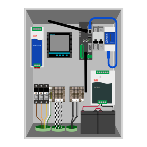
QUICK START GUIDE
WDAS-S3
WHAT'S IN THE BOX
• Wiring diagram
• (2) Antennas
• Mounting hardware
• Desiccant packs
(leave in box)
DAS INSTALLATION
MOUNTING
Attach brackets to the rear of the enclosure.
DO NOT drill holes through the enclosure for mounting.
Always use external mounting brackets.
CONDUIT
If mounted outdoors, ingress conduit ONLY from the bottom of
the enclosure to prevent water ingress into the enclosure.
POT the conduit penetrations according to your project's
guidelines to prevent water and moisture ingress.
DO NOT penetrate in the area marked by a red outline. This is
where batteries will be installed.
POWER
The DAS is powered from L1-N, so L1 and Neutral must be
connected in for the DAS to work correctly.
CURRENT TRANSFORMERS
The WDAS-S3 ONLY supports 333mV CTs.
Note: The Source arrow of the CTs should face toward the grid point
of interconnection (upstream of the inverters).
The current transformers connect via the terminal blocks in the
middle of the enclosure.
Ensure that the mapping of CTs in each terminal block (1-3
from left to right) matches up to the voltage phases (1-3 from
left to right).
REQUIRED TOOLS
• Mounting and drilling tools
• Torque screwdriver capable of
21 in-Ib
WDR-120-24
L1
L2
L3
TORQUE
Connection
Voltage input (breaker, L1/L2/L3)
Voltage input (N/GND)
CT terminals
RS-485 terminals
UPS controller battery terminals
ANTENNAS
Remove the antennas from the materials bag and install them
on the Digi modem as shown above. They should be screwed
onto the SMA connectors "WWAN1" and "WWAN2. "
BATTERY INSTALLATION
MATERIALS
• (2) SLA batteries
• (2) harnesses
Make sure that the DC breaker that enables the UPS power is
OFF. This should be turned on after the batteries are installed.
As shown in picture above, daisy chain the batteries using the
red cable in the materials bag, then attach the batteries to the
UPS using the BAT+/BAT- cables. Kapton or electrical tape on
exposed terminals is recommended.
Note: Measure the voltage on BAT+/BAT- to ensure that the proper
voltage (~24V) is present. The voltage should be positive measuring
from BAT+ to BAT-.
AcuVim II
DUPS40
Torque (in-lb)
21
4.5
4.5
15.5
• Phillips head screwdriver
• Torque screwdriver
capable of 15.5 in-lb
• Multimeter
EDGE
CONTROLLER
7
Advertisement

Summary of Contents for Wattcher WDAS-S3
- Page 1 CURRENT TRANSFORMERS Make sure that the DC breaker that enables the UPS power is The WDAS-S3 ONLY supports 333mV CTs. OFF. This should be turned on after the batteries are installed. Note: The Source arrow of the CTs should face toward the grid point As shown in picture above, daisy chain the batteries using the of interconnection (upstream of the inverters).
- Page 2 SENSOR INSTALLATION PLANE OF ARRAY BLACK SHIELD Mount in the same orientation as the array. Place the sensor near the ORANGE geometric center of the array if possible, or at the end of a row near the center of the array. Ensure that there are no objects that could shade the BROWN sensor at the beginning or end of the day when the sun is low.