Table of Contents
Advertisement
Quick Links
Scroll Compressor Specifications for Vehicle Air Conditioning
Compressor model
Displacement
Refrigerant
Power supply
Applicable standards
<Related Documents>
Detailed precautions when using: Engineering Manual
Installation details: Installation Manual
Be sure to read the above attached documents.
Signature by supplier
Hitachi-Johnson Controls
Air Conditioning,Inc.
2021 12 01
SHIMIZU WORKS
Hitachi-Johnson Controls Air Conditioning, Inc Shimizu Factory
Note: These Specifications are subject to change without notice according to our company's circumstances. However, this may
not apply in a case where contracts are signed and concluded by both the supplier and the purchaser.
be provided by the supplier in advance based on the items specified in this document.
CA47TLA-D2PE3
3
47cm
/rev
3φ380-415V 50Hz
390 Muramatsu, Shimizu-ku, Shizuoka-City, Shizuoka Prefecture
Specification No.: SSTSM-19013
December 1, 2021
CA56TLA-D2PE3
56cm
R134a
3φ380-415V 50Hz
CE、RoHS
Approval and signature by customer
3
/rev
Notice of change will
Advertisement
Chapters
Table of Contents

Related Manuals for Hitachi CA47TLA-D2PE3


Summary of Contents for Hitachi CA47TLA-D2PE3
- Page 1 Air Conditioning,Inc. 2021 12 01 SHIMIZU WORKS Hitachi-Johnson Controls Air Conditioning, Inc Shimizu Factory 390 Muramatsu, Shimizu-ku, Shizuoka-City, Shizuoka Prefecture Note: These Specifications are subject to change without notice according to our company’s circumstances. However, this may not apply in a case where contracts are signed and concluded by both the supplier and the purchaser.
-
Page 2: Table Of Contents
2.RANGE OF DELIVERY AND SPECIFICATIONS 3.GENERAL SPECIFICATIONS 4.RELATED LAWS AND REGULATIONS 5.COMMON SPECIFICATIONS FOR COMPRESSORS 6.WORKING RANGE 7.PERFORMANCE DATA 7-1.Model: CA47TLA-D2PE3 7-2.Model: CA56TLA-D2PE3 8.DIMENSIONAL DRAWING OF SCROLL COMPRESSOR 9.OPTIONAL PARTS LIST 10.ASSEMBLY DRAWING FOR COMPRESSOR VIBRATION PROOF RUBBER 11.DISCHARGE GAS THERMOSTAT SET 11-1.DISCHARGE GAS THERMOSTAT SET... -
Page 3: 1.Scope Of Application
*DGT-D is a standard product. Thermostat set DGT-E DGT-D: Lead wire 300 mm DGT-E: Lead wire 2,500 mm 3.GENERAL SPECIFICATIONS Hermetic type scroll compressor Type CA47TLA-D2PE3 CA56TLA-D2PE3 Model AC three-phase, 380-415V 50Hz Power supply 342 – 456 Operating voltage range R134a... -
Page 4: 4.Related Laws And Regulations
This compressor was examined under the standard installation environment using Vibration Proof Rubber, which is the Hitachi standard mounting assembly and was confirmed to meet the standards “IEC61373 (1999), Category 1, Class B.” When you use a product other than the specified rubber hardness product, it is necessary to confirm that the above standards are met. - Page 5 5.3 Insulation Distance IEC60335-2-34 shall apply. 5.4 Insulation Resistance Insulation resistance should be measured between the charging part and non-charging metal part using the 500V insulation resistance tester at room temperature and normal humidity, and it should be 10MΩ or higher. 5.5 Withstand Voltage After the test in 5.4 is complete, apply AC voltage using the gradually ramp method between the charging part and non-charging metal part (2E + 1000)V, (E: rated voltage).
- Page 6 5.12 Occurrence of Problems If problems occur after delivery, both parties shall raise them promptly and solve them in good faith. 5.13 Warranty Only when production defects are found within two years after production of the compressor, and our company recognizes the production defects, will a replacement product be supplied. Any defects occurred by other causes are not covered by the warranty: ex) when scroll compressors are operated under conditions that deviate from the delivery specifications and the Engineering Manual, or in an environment where moisture, dust, liquid return and...
-
Page 7: 6.Working Range
6.WORKING RANGE (Pressure and Temperature) ET = -1.0 Ps = 0.182 CT = 46.7 Pd = 1.11 Continuously Working Range CT = 38.7 Pd = 0.88 ET = 7.9 Ps = 0.285 Evaporating Temperature ET ( ℃ ) Suction Pressure Ps ( MPaG ) Notes: 1. -
Page 8: 7.Performance Data
7.PERFORMANCE DATA Rating Conditions 7-1. Model: CA47TLA-D2PE3 Power Source Three-phase 380V Frequency 50Hz Refrigerant R134a Return Gas Superheating 11.1K Liquid Subcooling 8.3K Cooling capacity〔kW〕 ET〔 ℃ 〕 〕 ℃ CT〔 3.35 4.20 5.18 6.32 7.63 3.13 3.96 4.91 6.00 7.27 8.73... -
Page 9: Model: Ca56Tla-D2Pe3
7-2. Model: CA56TLA-D2PE3 Rating Conditions Power Source Three-phase 380V Frequency 50Hz Refrigerant R134a Return Gas Superheating 11.1K Liquid Subcooling 8.3K Cooling capacity〔kW〕 ET〔 ℃ 〕 〕 ℃ CT〔 4.12 5.16 6.37 7.76 9.38 3.85 4.86 6.02 7.37 8.93 10.72 3.56 4.54 5.67 6.97... -
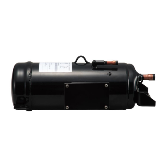
Page 10: 8.Dimensional Drawing Of Scroll Compressor
8.DIMENSIONAL DRAWING OF SCROLL COMPRESSOR Model: CA47TLA-D2PE3, CA56TLA-D2PE3 Refrigerant Discharge Refrigerant Suction Connection Name Plate Connection Terminal Box Note: 1.Unit is mm. -
Page 11: 9.Optional Parts List
9.OPTIONAL PARTS LIST Optional parts are sold separately. Refer to the following table and place an order as needed. Product name Quantity Vibration Proof Rubber Vibration Proof Rubber 1 (Model: VPR-A2) Vibration Proof Rubber 2 Spacer Washer M10 Bolt Spring Washer M10 Nut Discharge Gas Standard specifications... -
Page 12: 10.Assembly Drawing For Compressor Vibration Proof Rubber
10.ASSEMBLY DRAWING FOR COMPRESSOR VIBRATION PROOF RUBBER Name Remarks Compressor (leg) ※ Vibration Proof Rubber 1 Rubber hardness 55° ※ Vibration Proof Rubber 2 Rubber hardness 55° ※ Spacer Base of Unit ※ Washer ※ M10 Bolt tightening torque 35 N・m ※... -
Page 13: 11.Discharge Gas Thermostat Set
11.DISCHARGE GAS THERMOSTAT SET 11-1. DISCHARGE GAS THERMOSTAT : AC250V 3.0A or less ( resistance load ) Contact capacity : UT-430K Thermostat model : OPEN 130 ℃ ± 5 ℃, CLOSE 100 ℃ ± Set temperature 15°C Operating voltage range : AC180-220V, 0.005 - 3.0A and current range DC5 - 24V, 0.005 - 0.020A :... -
Page 14: Protection Rating (Ip Codes)
12.PROTECTION RATING OF THE POWER SUPPLY TERMINAL BOX (IP CODES) Protection rating of the power supply terminal box of this compressor is specified as follows: 12-1.PROTECTION RATING (IP CODES) Applicable standards IEC60529: 2001 Protection rating IP65 12-2.IP65 CRITERIA FOR JUDGEMENT “Protection against water,”... -
Page 15: Scope Of Ip65 Application
12-3.SCOPE OF IP65 APPLICATION With the power supply terminal box as an outline, it shall apply to the portions excluding the cable gland part (dust and water ingress routes illustrated in Fig. 12-1.) *A customer is requested to examine the cable gland part during the prototype test, and confirm the protection rating. -
Page 16: 13.Nameplate Marking Contents
13. NAMEPLATE MARKING CONTENTS 13-1. Model: CA47TLA-D2PE3 13-2. Model: CA56TLA-D2PE3... -
Page 17: 14.Packing Specifications
14.PACKING SPECIFICATIONS * Packing specifications are described in the following drawing. * Eight compressors can be contained per pack. Customers are requested to place an order for every 8 units excluding sample machines. Compressor is screwed to the wooden frame base. (Coach screw, Washer and Rubber sheet) Plastic bag Notes:... - Page 18 – ENGINEERING MANUAL – CA SERIES AND GA SERIES SCROLL COMPRESSOR FOR VEHICLE AIR CONDITIONING R134a MODELS CA47TLA-D2PE3 CA56TLA-D2PE3 GA120TLA-D2PE3 ESTSM-21020 June 9, 2021...
-
Page 19: Revision History Date
Contents 1. RANGE OF APPLICATION AND PRECAUTIONS FOR USE 1-1 RANGE OF APPLICATION 1-2 PRECAUTIONS FOR REFRIGERANT CYCLE DESIGN 1-3.Precautions for Electrical Wiring 1-4.PRECAUTIONS WHEN STORING AND TRANSPORTING 1-5.PRECAUTIONS FOR CONSTRUCTION 2. BASIC ELECTRICAL WIRING DIAGRAM (for 3 phase) 2-1.CONTROL SEQUENCE 2-2. - Page 20 IMPORTANT NOTICE TO USE THE COMPRESSOR PROPERLY, CAREFULLY READ AND FULLY UNDERSTAND THIS MANUAL. CAUTIONARY INSTRUCTIONS IMPORTANT READ THESE “CAUTIONARY INSTRUCTIONS” CAREFULLY BEFORE USING THE COMPRESSOR. 1. INSTALLATION WARNING ** TO AVOID ELECTRICAL SHOCK AND FIRE** Use this compressor on an earthed system only. WARNING ** TO AVOID LEAKAGE OF ELECTRICITY ** Be sure to use an ELB (Earth Leakage Breaker).
- Page 21 WARNING ** TO AVOID EXPLOSION AND FIRE CAUSED BY CHARGING AND MIXING DIFFERENT TYPES OF REFRIGERANTS OTHER THAN THE SPECIFIED ONE ** DO NOT charge or mix different types of refrigerants other than the specified one in the cycle. ・Be sure to use nitrogen gas during the leakage test and the airtightness test. ・Ensure that you use the refrigerant pipes at the time of installation before operating the compressor.
-
Page 22: Range Of Application And Precautions For Use
1.RANGE OF APPLICATION AND PRECAUTIONS FOR USE 1-1.RANGE OF APPLICATION (1) Introduction *This compressor shall be used according to the specifications and specified conditions described in this engineering manual, and it shall not be used based on other specifications. Optional parts shall also be used as specified, and specified parts shall be used for service as well. - Page 23 (10) Temperature of Terminal Plugs The temperature of the terminal plugs should be below 150℃ to ensure safety in all operating conditions. (11) Liquid back to the Compressor Refrigerants to return to the compressor should be superheated in all operating conditions. Liquid return to the compressor is prohibited.
-
Page 24: Precautions For Refrigerant Cycle Design
1-2.PRECAUTIONS FOR REFRIGERANT CYCLE DESIGN (1) Oil Return and Oil Quantity *The refrigerant cycle should be so designed that the oil return to the compressor should always be secured, and oil should not accumulate. *The compressor should be operated by keeping the shaft horizontal, but in reality the compressor should be operated with a maximum of 5.6 degrees (9.8%) inclination in all directions. - Page 25 φ 160 series Unit: mm Power supply terminal box ←Top ←Bottom Oil Sight glass Main model CA47TLA CA56TLA Specified charged capacity [Litter] Top [Litter] 0.95 0.85 Bottom[Litter] 0.35 0.35 * Check the oil level visible in the sight glass. φ 190 series Unit: mm Power supply terminal box ←Top...
- Page 26 (3) Safety Device for Protection from High Pressure and Low Pressure *Be sure to use a high-pressure switch or safety valve. *Be sure to use a low-pressure cut switch. *Considering the tolerance of the pressure switch, the device should be set to values so that it can be within the operation pressure limits stipulated in Clause 6 “Working Range (Pressure and Temperature)”...
-
Page 27: Precautions For Electrical Wiring
1-3.Precautions for Electrical Wiring (1) Earthing Cables Earthing cables should be connected. (2) Over Current Relay The compressor must be protected from over current by using the over current relay. The compressor must be protected to ensure that it will stop at the maximum allowable current or less stipulated in Clause 3 “General Specifications”... -
Page 28: Precautions When Storing And Transporting
1-4.PRECAUTIONS WHEN STORING AND TRANSPORTING (1) Storage *The compressor should be stored in a clean, dry place. *The compressor is a horizontal type. It should be transported and stored in a horizontal position. *Do not store the compressor outdoors or in a place where water-drops from the circumferences are poured on to the compressor. - Page 29 (3) Refrigerant Pipe Connection *The oil in this compressor is synthetic oil, and it has a higher moisture-absorbent than conventional oil. Do not leave the compressor with the suction and discharge pipes open to the air for a long period of time. As a guide, it should be limited to within 3 to 5 minutes. *To avoid the oxidation of pipes, brazing should be carried out while nitrogen flows into the brazing junction.
- Page 30 (8) Precautions When Charging Refrigerant Oil * Because the appropriate amount of refrigerant oil is charged in the compressor before shipping, no additional amount should be charged, in principle. *If you have no choice but to charge additional oil, you will need to meet the requirements for the relationships between refrigerant charged capacity and oil charged capacity prescribed in 1-5.(7).
-
Page 31: Basic Electrical Wiring Diagram (For 3 Phase)
2. BASIC ELECTRICAL WIRING DIAGRAM (for 3 phase) The following electrical wiring diagram shows a typical example of protection designs. The electrical circuits to protect the compressor should be designed in consideration of system designs and the actual usage state. Power Supply:3φ... -
Page 32: Control Sequence
2-1.CONTROL SEQUENCE The compressor is protected by OCR (overcurrent relay for compressor motor) and a DT (discharge gas thermostat). These safety devices are automatically reset. Therefore, all control circuits should be designed to guard against harmful on-off restarting by the installation of the automatic reset safety device. A typical control circuit for the scroll compressors is shown in Clause 2 “Basic Electrical Wiring Diagram (for 3 phase).”... -
Page 33: Power Supply Terminal Box Structure
3.POWER SUPPLY TERMINAL BOX STRUCTURE φ 160 series φ 190 series... - Page 34 Mark Name Remarks Terminal Plug (Power Supply) Terminal Screw (Power Supply) Size: M5, tightening torque: 2.4 - 2.8N・m Connector Block Terminal Box Cover Gasket Silicon sponge Screw Size: M5, tightening torque: 2N・m Terminal Screw (Earthing) Size: M5, tightening torque: 2.4 - 2.8N・m Toothed Lock Washer Washer ※...
-
Page 35: Example Of Standard Refrigerant Cycle
(7) The power lines from the terminal box should not contact the surface of the compressor. If they come into contact with it, the power lines will be damaged. (8) The gasket is installed in the terminal box. The procedures for removing and re-installing the plug cover are as follows: *Removing the Cover When the gasket sticks out on the terminal box side and the cover side respectively and the...