Table of Contents
Advertisement
Quick Links
PRINTED IN EUROPE (ACI) 2008, 02
PART NO.
EM1U1-EN3-1
Operator's Manual
120
class
-3
110
110M
130
130LCN
-3
-3
-3
•
•
•
180
class
-3
160LC
180LC
180LCN
-3
-3
•
•
200
class
-3
210
210LC
210LCN
-3
-3
-3
•
•
270
class
-3
250LC
250LCN
280LC
-3
-3
•
•
330
class
-3
350LC
350LCN
-3
-3
•
Hydraulic Excavator
Serial No.
ZX120
class
080001 and up
-3
ZX180
class
010372 and up
-3
ZX200
class
202803 and up
-3
ZX270
class
021321 and up
-3
ZX330
class
052046 and up
-3
-3
-3
240N
-3
•
280LCN
-3
-3
•
Advertisement
Table of Contents

Related Manuals for Hitachi 120-3 class


Summary of Contents for Hitachi 120-3 class
- Page 1 PART NO. EM1U1-EN3-1 Operator's Manual class 110M 130LCN • • • class 160LC 180LC 180LCN • • class 210LC 210LCN 240N • • • class 250LC 250LCN 280LC 280LCN • • • class 350LC 350LCN • Hydraulic Excavator Serial No. ZX120 class 080001 and up...
- Page 2 CERNING COMPLIANCE. detailed information. Hitachi machine models are classified into 5 classes and 1 model as shown in the table below. When referring to the texts and/or illustrations indicated with the applicable machine class names in this manual, check that the machine models concerned are included using this table.
- Page 3 INDEX MACHINE NUMBERS SAFETY SAFETY SIGNS COMPONENTS NAME OPERATOR’S STATION BREAK-IN OPERATING THE ENGINE DRIVING THE MACHINE OPERATING THE MACHINE TRANSPORTING MAINTENANCE HYDRAULIC CIRCUIT AND ELECTRICAL CIRCUIT MAI N TENANCE UNDER SPECI A L ENVI R ONMENTAL CONDI T I O NS STORAGE TROUBLESHOOTING SPECIFICATIONS...
- Page 5 MACHINE NUMBERS The manufacturing Nos. explained in this group is the individ- ual number (serial No.) given to each machine and hydraulic components. These numbers are requested when inquiring any information on the machine and/or components. Fill these serial Nos. in the blank spaces in this group to immediately make them available upon request.
- Page 6 MACHINE NUMBERS TRAVEL MOTOR TYPE: MFG. NO.: M178-07-047 SWING MOTOR TYPE: MFG. NO.: M178-07-086 HYDRAULIC PUMP TYPE: MFG. NO.: M157-00-004...
-
Page 7: Table Of Contents
CONTENTS MACHINE NUMBERS Beware of Exhaust Fumes............S-27 Precautions for Welding and Grinding ......... S-27 Avoid Heating Near Pressurized Fluid Lines ....... S-28 SAFETY Avoid Applying Heat to Lines Containing Recognize Safety Information ............S-1 Flammable Fluids ..............S-28 Understand Signal Words .............S-1 Remove Paint Before Welding or Heating ...... - Page 8 CONTENTS Horn Switch ..................1-53 Operating in Water or Mud ............4-7 Cigar Lighter ...................1-54 Parking the Machine on Slopes ..........4-8 Cab Light ..................1-55 Parking the Machine ..............4-8 Installing Fire Extinguisher (Optional) ........1-55 OPERATING THE MACHINE Pilot Control Shut-off Lever ............1-56 Engine Stop Switch ..............1-56 Control Lever (Iso Pattern) ............
- Page 9 CONTENTS Maintenance Guide ..............7-10 Change Bucket ...............7-72 A. Greasing ..................7-16 Convert Bucket Connection Into Face Shovel .....7-73 Front Joint Pins ...............7-16 Adjust Bucket Linkage ............7-74 Swing Bearing .................7-18 Remove Travel Levers ............7-75 Swing Internal Gear ..............7-19 Check and Replace Seat Belt Check ........7-75 B.
- Page 10 CONTENTS Bucket Types and Applications (ZX160LC-3) ....12-15 Specifications (ZX130-3 with Blade) ........13-13 Specifications (ZX180LC-3, 180LCN-3) ........12-16 Working Ranges (ZX130-3 with Blade) .......13-14 Working Ranges (ZX180LC-3, 180LCN-3) ......12-17 Shoe Types and Applications Shoe Types and Applications (ZX130-3 with Blade) ............13-15 (ZX180LC-3, 180LCN-3) ............12-19 Offset Arm Front .................13-16 Bucket Types and Applications Offset Direction and Working Range ........13-17...
- Page 11 CONTENTS Lifting Capacities ................13-48 INDEX ....................14-1...
- Page 12 CONTENTS MEMO .......................................................................................................................................................................................................................................................................................................................................................................................................................................................................................................................................................................................................................................................................................................................................................................................................................................................................................................................................................................................................................................................................................................................................................................................................................................................................................................................................................................................................................................................................................................................................................................................................................................................................................................................................................................................................................................................................
-
Page 13: Safety
SAFETY RECOGNIZE SAFETY INFORMATION • These are the SAFETY ALERT SYMBOLS. • When you see these symbols on your machine or in this manual, be alert to the potential for personal injury. • Follow recommended precautions and safe operating practices. 001-E01A-0001 SA-688 UNDERSTAND SIGNAL WORDS... -
Page 14: Follow Safety Instructions
Hitachi Warranty Policy. • Do not use attachments and/or optional parts or equip- ment not authorized by Hitachi. Failure to do so may deteriorate the safety, function, and/or service life of the machine. In addition, personal accident, machine trouble,... -
Page 15: Prepare For Emergencies
SAFETY PREPARE FOR EMERGENCIES • Be prepared if a fire starts or if an accident occurs. • Keep a first aid kit and fire extinguisher on hand. • Thoroughly read and understand the label attached on the fire extinguisher to use it properly. •... -
Page 16: Inspect Machine
SAFETY INSPECT MACHINE • Inspect your machine carefully each day or shift by walking around it before you start it to avoid personal injury. • In the walk-around inspection be sure to cover all points described in the “PRE-START INSPECTION” chapter in the operator’s manual. -
Page 17: Use Handholds And Steps
SAFETY USE HANDHOLDS AND STEPS • Falling is one of the major causes of personal injury. • When you get on and off the machine, always face the machine and maintain a three-point contact with the steps and handrails. • Do not use any controls as hand-holds. •... -
Page 18: Fasten Your Seat Belt
SAFETY FASTEN YOUR SEAT BELT • If the machine should overturn, the operator may become injured and/or thrown from the cab. Additionally the opera- tor may be crushed by the overturning machine, resulting in serious injury or death. • Prior to operating the machine, thoroughly examine web- bing, buckle and attaching hardware. -
Page 19: Operate Only From Operator's Seat
SAFETY OPERATE ONLY FROM OPERATOR'S SEAT • Inappropriate engine starting procedures may cause the machine to runaway, possibly resulting in serious injury or death. • Start the engine only when seated in the operator's seat. • NEVER start the engine while standing on the track or on ground. -
Page 20: Precautions For Operations
SAFETY PRECAUTIONS FOR OPERATIONS • Investigate the work site before starting operations. • Be sure to wear close fitting clothing and safety equip- ment appropriate for the job, such as a hard hat, etc. when operating the machine. • Clear all persons and obstacles from area of operation and machine movement. -
Page 21: Investigate Job Site Beforehand
SAFETY INVESTIGATE JOB SITE BEFOREHAND • When working at the edge of an excavation or on a road shoulder, the machine could tip over, possibly resulting in serious injury or death. • Investigate the configuration and ground conditions of the job site beforehand to prevent the machine from fall- ing and to prevent the ground, stockpiles, or banks from collapsing. -
Page 22: Equipment Of Head Guard, Rops, Fops
SAFETY EQUIPMENT OF HEAD GUARD, ROPS, FOPS In case the machine is operated in areas where the possibility of falling stones or debris exist, equip a head guard, ROPS, or FOPS according to the potential hazardous conditions. (The standard cab for this machine corresponds to ROPS and FOPS.) ROPS: Roll-Over Protective Structure FOPS: Falling Object Protective Structure SA-490... -
Page 23: Drive Machine Safely
SAFETY DRIVE MACHINE SAFELY • Before driving the machine, always confirm that the travel levers/pedals direction corresponds to the direction you wish to drive. • Be sure to detour around any obstructions. • Avoid traveling over obstructions. Soil, fragments of rocks, and/or metal pieces may scatter around the machine. - Page 24 SAFETY • Driving across the face of a slope or steering on a slope may cause the machine to skid or turnover. If the direc- tion must be changed, move the machine to level ground, then, change the direction to ensure safe operation. •...
-
Page 25: Avoid Injury From Rollaway Accidents
SAFETY AVOID INJURY FROM ROLLAWAY ACCIDENTS • Death or serious injury may result if you attempt to mount or stop a moving machine. To avoid rollaways: • Select level ground when possible to park machine. • Do not park the machine on a grade. •... -
Page 26: Avoid Injury From Back-Over And Swing Accidents
SAFETY AVOID INJURY FROM BACK-OVER AND SWING ACCIDENTS • If any person is present near the machine when backing or swinging the upperstructure, the machine may hit or run over that person, resulting in serious injury or death. To avoid back-over and swing accidents: •... -
Page 27: Keep Person Clear From Working Area
SAFETY KEEP PERSON CLEAR FROM WORKING AREA • A person may be hit severely by the swinging front attach- ment or counterweight and/or may be crushed against an other object, resulting in serious injury or death. • Keep all persons clear from the area of operation and machine movement. -
Page 28: Avoid Tipping
SAFETY AVOID TIPPING DO NOT ATTEMPT TO JUMP CLEAR OF TIPPING MA- CHINE---SERIOUS OR FATAL CRUSHING INJURIES WILL RESULT MACHINE WILL TIP OVER FASTER THAN YOU CAN JUMP FREE FASTEN YOUR SEAT BELT • The danger of tipping is always present when operating on a grade, possibly resulting in serious injury or death. -
Page 29: Dig With Caution
SAFETY DIG WITH CAUTION • Accidental severing of underground cables or gas lines may cause an explosion and/or fire, possibly resulting in serious injury or death. • Before digging check the location of cables, gas lines, and water lines. • Keep the minimum distance required, by law, from cables, gas lines, and water lines. -
Page 30: Avoid Power Lines
SAFETY AVOID POWER LINES • Serious injury or death can result if the machine or front at- tachments are not kept a safe distance from electric lines. • When operating near an electric line, NEVER move any part of the machine or load closer than 3 m plus twice the line insulator length. -
Page 31: Protect Against Flying Debris
SAFETY PROTECT AGAINST FLYING DEBRIS • If flying debris hit eyes or any other part of the body, serious injury may result. • Guard against injury from flying pieces of metal or debris; wear goggles or safety glasses. • Keep bystanders away from the working area before strik- ing any object. -
Page 32: Transport Safely
SAFETY TRANSPORT SAFELY • Take care the machine may turn over when loading or un- loading the machine onto or off of a truck or trailer. • Observe the related regulations and rules for safe trans- portation. • Select an appropriate truck or trailer for the machine to be transported. -
Page 33: Practice Safe Maintenance
SAFETY PRACTICE SAFE MAINTENANCE To avoid accidents: • Understand service procedures before starting work. • Keep the work area clean and dry. • Do not spray water or steam inside cab. • Never lubricate or service the machine while it is moving. •... -
Page 34: Warn Others Of Service Work
SAFETY • Sufficiently illuminate the work site. Use a maintenance work light when working under or inside the machine. • Always use a work light protected with a guard. In case the light bulb is broken, spilled fuel, oil, antifreeze fluid, or window washer fluid may catch fire. -
Page 35: Prevent Parts From Flying
SAFETY PREVENT PARTS FROM FLYING • Grease in the track adjuster is under high pressure. Failure to follow the precautions below may result in serious injury, blindness, or death. • Do not attempt to remove GREASE FITTING or VALVE AS- SEMBLY. -
Page 36: Prevent Burns
SAFETY PREVENT BURNS Hot spraying fluids: • After operation, engine coolant is hot and under pressure. Hot water or steam is contained in the engine, radiator and heater lines. Skin contact with escaping hot water or steam can cause severe burns. •... -
Page 37: Avoid High-Pressure Fluids
SAFETY AVOID HIGH-PRESSURE FLUIDS • Fluids such as diesel fuel or hydraulic oil under pressure can penetrate the skin or eyes causing serious injury, blindness or death. • Avoid this hazard by relieving pressure before disconnect- ing hydraulic or other lines. •... -
Page 38: Prevent Fires
SAFETY PREVENT FIRES Check for Oil Leaks: • Fuel, hydraulic oil and lubricant leaks can lead to fires. • Check for oil leaks due to missing or loose clamps, kinked hoses, lines or hoses that rub against each other, damage to the oil-cooler, and loose oil-cooler flange bolts. -
Page 39: Evacuating In Case Of Fire
SAFETY EVACUATING IN CASE OF FIRE • If a fire breaks out, evacuate the machine in the following way: • Stop the engine by turning the key switch to the OFF position if there is time. • Use a fire extinguisher if there is time. •... -
Page 40: Avoid Heating Near Pressurized Fluid Lines
SAFETY AVOID HEATING NEAR PRESSURIZED FLUID LINES • Flammable spray can be generated by heating near pres- surized fluid lines, resulting in severe burns to yourself and bystanders. • Do not heat by welding, soldering, or using a torch near pressurized fluid lines or other flammable materials. -
Page 41: Beware Of Asbestos Dust
• Keep bystanders out of the work site during operation. • Asbestos might be present in imitation parts. Use only SA-029 genuine Hitachi Parts. PREVENT BATTERY EXPLOSIONS • Battery gas can explode. • Keep sparks, lighted matches, and flame away from the top of battery. -
Page 42: Handle Chemical Products Safely
• Improperly disposing of waste can threaten the environ- ment and ecology. Potentially harmful waste used with HITACHI equipment includes such items as oil, fuel, coolant, brake fluid, filters, and batteries. • Use leakproof containers when draining fluids. Do not use food or beverage containers that may mislead someone into drinking from them. -
Page 43: Safety Signs
Use the part No. indicated under the right corner of each safety sign illustration when placing an order of it to the Hitachi dealer. RIGHT WINDOW ZX180-3 class... - Page 44 SAFETY SIGNS/Europe/Asia/Middle and Near East Model Only 1. WARNING! Prior to operation, maintenance, disassembling, and trans- portation of the machine, be sure to read and understand the Operator’s Manual. SS4420332 If the parked machine is unexpectedly moved, serious injury or death due to crushing may result. Be sure to lower the front attachment to the ground, lock the control levers, and remove the engine key before leaving the machine unat- tended.
- Page 45 SAFETY SIGNS/Europe/Asia/Middle and Near East Model Only When moving the seat height/tilt lever downward, press the lever grip with a palm from the top side. Do not grasp the lever grip to operate the lever, possibly resulting in pinch of your fingers into the seat stand.
- Page 46 SAFETY SIGNS/Europe/Asia/Middle and Near East Model Only SS3106039 Sign indicates a hazard of being hit by the working device of the machine. Keep away from machine during operation. SS3089581 Sign indicates a hazard of a flying plug from track adjuster that could cause injury.
- Page 47 SAFETY SIGNS/Europe/Asia/Middle and Near East Model Only Sign indicates a burn hazard from compressed air and spurt- ing hot oil if the oil inlet is uncapped during or right after operation. Read manual for safe and proper handling. SS4459928 Sign indicates a burn hazard from spurting hot water or oil if radiator or hydraulic tank is uncapped while hot.
- Page 48 SAFETY SIGNS/Europe/Asia/Middle and Near East Model Only Sign indicates a crush hazard by rotation of upper structure of the machine. Keep away from swinging area of machine. SS3086090 Sign indicates a burn hazard from spurting hot water or oil if radiator or hydraulic tank is uncapped while hot.
- Page 49 SAFETY SIGNS/Europe/Asia/Middle and Near East Model Only Sign indicates an electrical hazard from handling the cable. Read manual for safe and proper handling. SS4459714 Sign indicates an explosion hazard. Keep fire and open flames away from this area. SS4460067 Skin contact with electrolyte will cause burns. Splashed electrolyte into eyes will cause blindness.
- Page 50 SAFETY SIGNS/Europe/Asia/Middle and Near East Model Only MEMO ....................................................................................................................................................................................................................................................................................................................................................................................................................................................................................................................................................................................................................................................................................................................................................................................................................................................................................................................................................................................................................................................................................................................................................................................................................................................................................................................................................................................................................................................................................................................................................................................................................................................................
-
Page 51: Components Name
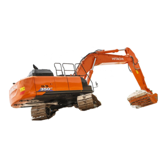
OPERATOR'S STATION COMPONENTS NAME COMPONENTS NAME 1- Bucket 2- Bucket Cylinder 3- Arm 4- Arm Cylinder 5- Boom Cylinder 6- Boom 7- Fuel Tank 8- Hydraulic Oil Tank 9- Engine 10- Counterweight 11- Travel Device 12- Track 13- Front Idler 14- Cab M1U1-01-005... -
Page 52: Operator's Station
OPERATOR'S STATION CAB FEATURES Std. Model 1- Left Control Lever/Horn Switch (On Top of Lever) 2- Left Travel Pedal 3- Left Travel Lever 4- Right Travel Lever 5- Right Travel Pedal 6- Attachment Pedal (Optional) 7- Right Control Lever/Power Boost Switch (Except ZX120-3 class) 8- Multi Function Monitor Panel 9- Switch Panel... -
Page 53: Multi Function Monitor
OPERATOR'S STATION MULTI FUNCTION MONITOR How To Use Screens Displaying Basic Screen IMPORTANT: Start the engine after the basic screen is displayed. When the key switch is turned to the ON position, the starting screen displays for about two seconds and the basic screen displays. -
Page 54: Outline
OPERATOR'S STATION OUTLINE 1 - Work Mode Display 2 - Auto-Idle Display 3 - Overload Alarm Display (Optional) 4 - Auxiliary 5 - Auxiliary 6 - Preheat Display 7 - Work Mode Display 8 - Hour Meter 9 - Auxiliary 10 - Fuel Gauge 11 - Mail Display (Optional) 12 - Auxiliary... - Page 55 OPERATOR'S STATION Display of Meters • Work Mode Items to be displayed 8. Hour Meter 10. Fuel Consumption Gauge 14. Clock 16. Menu 22. Coolant Temperature Gauge Work Mode Display • The attachments being used are displayed. M1U1-01-112 Digging mode T1V1-05-01-108 Attachment mode Breaker...
- Page 56 OPERATOR'S STATION • Auto-Idle Display (2) When selecting auto-idle from the switch panel, the auto- idle display (2) is displayed. When the key is turned ON, the data blinks for 10 seconds. Overload Alarm Display (3) (optional) T1V1-05-02-002 The system measures the load of suspended load from the bottom pressure of boom cylinder.
-
Page 57: Menu Screen (23)
OPERATOR'S STATION Menu Screen (23) Press menu key (16) on the basic screen to display main menu screen (23). Select the desired menu by operating key (25) located under keys on icon display area (24). T1V5-05-01-019... -
Page 58: Hour Meter
OPERATOR'S STATION Hour Meter Total (accumulated) machine operation hours counted since the machine started working, are displayed in the unit of HOUR (h). One digit after the decimal point indicates the tenths of an hour (6 minutes). M81U-01-058 Fuel Gauge The fuel amount in the fuel tank is indicated. -
Page 59: Menu Key
OPERATOR'S STATION Menu Key Shifts the basic screen to the menu screen. M1U1-01-042 Optional Function Key The desired preset optional function can be selected by oper- ating these keys even though the menu key is not operated. F1 : Work Mode Selection F2 : Auxiliary M1U1-01-043 F3 : Mail (Optional) -
Page 60: Coolant Temperature Gauge
OPERATOR'S STATION Coolant Temperature Gauge Indicates the engine coolant temperature. Normally the needle is around the center of the scale during operation. M1U1-01-047 Operating Status Icon Display Displays icons indicating the current status of the attachment (1) selected at the work mode selection screen and operation modes such as the auto-idle system (2) and preheat display (3), etc when these systems are activated. - Page 61 Displaying Basic Screen by Password Input (Optional) IMPORTANT: When required to activate the TEN-key func- tion (ignition block system), consult your nearest Hitachi dealer. If the password ever escapes the customer’s memory, the machine must be modified. Be extra careful not to forget the password.
- Page 62 OPERATOR'S STATION In Case of Inputting an Incorrect Password 1. If inputting an incorrect password, the message “Pass- word is incorrect. ” displays by pushing the determination key. Password Input Screen T1V5-05-01-093 Determination Key Delete Key T1V5-05-01-002 2. Return to the password input screen, by pushing the back key.
- Page 63 OPERATOR'S STATION 3. If inputting an incorrect password three times, a screen displays informing that the security lock has been ap- plied, and a buzzer rings for thirty seconds. During that time, the buzzer does not stop ringing even if turning of the key switch ON/OFF.
- Page 64 OPERATOR'S STATION Extending Password Duration Time IMPORTANT: This operation is applicable only to those machines that display the basic screen based upon password input. By using the password duration screen, password duration time can be set. When you restarting the machine, a pass- word need not be input within that timeframe.
-
Page 65: Alarm Occurrence Screen
OPERATOR'S STATION ALARM OCCURRENCE SCREEN In case any abnormality occurs, the alarm marks are displayed on the basic screen. When the number of alarms is two or less • T1V1-05-01-095 When the number of alarms is three or more • T1V1-05-01-096 1-15... - Page 66 OPERATOR'S STATION In case any abnormality occurs, push the key located under the alarm mark. The monitor displays the corrective action to the alarm situation. Push a Relevant Key T1V1-05-01-095 T1V5-05-01-013 1-16...
-
Page 67: Contents Of Alarms
Stop operation. Run the engine at slow idle speed and lower the cool- ant temperature. M178-01-036 Engine Warning Alarm Engine or engine related parts are abnormal. Consult your nearest Hitachi dealer. M183-01-080 Engine Oil Pressure Alarm Engine oil pressure has decreased. Immediately stop engine. Check engine oil system and oil level. - Page 68 OPERATOR'S STATION • Fuel Sensor Error Display Coolant Temperature Fuel Sensor Error When the fuel sensor is faulty or if the harness between Sensor Error Display Display fuel sensor and monitor unit is broken, the fuel sensor error display is displayed on the fuel gauge. •...
-
Page 69: Clock Setting
OPERATOR'S STATION Clock Setting Press menu key (2) on basic screen (1) to display main menu screen (3). Select time set menu (4) by pressing the key located under keys on icon display area and adjust the clock set. T1V1-05-01-123 Time Adjustment After selecting time set menu (4) by pressing the key locat- ed under... -
Page 70: Attachment Selection (Only Machines Equipped With Optional Parts)
OPERATOR'S STATION ATTACHMENT SELECTION (Only Machines Equipped with Optional Parts) IMPORTANT: Select the attachments from the work mode screen. In order to display the work mode screen, push work mode selection key F1 after basic screen displays, or select from main menu. Selecting an Attachment by Using Work Mode Selection Key F1 1. - Page 71 OPERATOR'S STATION Selecting an Attachment from Main Menu 1. When the basic screen displays, push the menu key and display main menu. 2. Select work mode from main menu by using keys 1 and 2 . Push determination key. Then, the work mode screen displays.
- Page 72 OPERATOR'S STATION Attachment Specification Screen Maximum Pump 2 Flow Rate Breaker 1 Maximum Engine Speed Accumulator Control Solenoid Valve: OFF Secondary Relief Selector Control Solenoid Valve: ON Three way Valve Control Solenoid Valve: ON The three way valve is connected to the hydraulic oil tank.
- Page 73 OPERATOR'S STATION Pulverizer 1 Maximum Pump 1 and 2 Flow Rate Maximum Engine Speed Accumulator Control Solenoid Valve: OFF Secondary Relief Selector Control Solenoid Valve: OFF Three way Valve Control Solenoid Valve: OFF The three way valve is connected to the control valve.
-
Page 74: Pump 2 Flow Rate Adjustment (Only Machines Equipped With Optional Parts)
OPERATOR'S STATION PUMP 2 FLOW RATE ADJUSTMENT (Only Machines Equipped with Optional Parts) IMPORTANT: This operation is effective when attachments are used. 1. When the basic screen displays, push the menu key and display main menu. 2. Select attachment adjustment from main menu by using keys 1 and 2 . -
Page 75: Displaying Operating Conditions
OPERATOR'S STATION DISPLAYING OPERATING CONDITIONS 1. When the basic screen displayed, push the menu key and display main menu. 2. Select operating conditions from main menu by using keys 1 and 2. Push the determination key. Then, the oper- ating conditions screen displays. 3. -
Page 76: Fuel Rate Display/No Display
OPERATOR'S STATION FUEL RATE DISPLAY/NO DISPLAY Fuel Rate Display 1. When the basic screen displays, push the menu key and display main menu. Menu Key Basic Screen T1V1-05-01-123 2. Select fuel rate display/No display from main menu by using keys 1 and 2. Push the determination key. Then, the fuel rate display/No display screen displays. - Page 77 OPERATOR'S STATION 4. Push key 6 , and the fuel rate display will be added to basic screen. Key 6 T1V5-05-01-119 Fuel Rate T1V1-05-01-007 1-27...
- Page 78 OPERATOR'S STATION Fuel Rate No Display 1. When the basic screen displays, push the menu key and display main menu. Fuel Gauge Menu Key Basic Screen T1V1-05-01-007 2. Select fuel rate display/No display from main menu by using keys 1 and 2 .
- Page 79 OPERATOR'S STATION 4. Push key 6 , and return to the basic screen. Key 6 T1V5-05-01-164 Basic Screen T1V1-05-01-123 1-29...
- Page 80 • (Only machines equipped with optional parts) IMPORTANT: When using overload alarm, consult your nearest Hitachi dealer. When the overload alarm switch is turned ON, the system measures load of the suspended load from bottom pressure of the boom cylinder. An alarm message is displayed and buzzer is rung, if overload is detected.
- Page 81 OPERATOR'S STATION Password Change (Optional) 1. After the basic screen is displayed, push the menu key in order to display the main menu. Menu Key Basic Screen T1V1-05-01-123 2. Select password change from main menu by using keys 1 and 2. Push the determination key. Then, the password change screen displays.
- Page 82 OPERATOR'S STATION NOTE: If inputting an incorrect password after pushing the determination key, the message “Password is incorrect.” displays. Push the back key and go back to the previous screen, input the password again. Back Key T1V5-05-01-044 5. The message “Enter password to be registered. ” displays. Then, input a new password with three or four digits and push the determination key.
- Page 83 OPERATOR'S STATION 7. The message “Re-enter password. ” displays. Then, input a new password again and push the determination key. 8. If inputting the password again, push the delete key in order to delete the entered characters. T1V5-05-01-132 Determination Key Delete Key T1V5-05-01-133 9.
-
Page 84: Back Monitor Settings
OPERATOR'S STATION BACK MONITOR SETTINGS IMPORTANT: Image displayed on the back monitor is of auxiliary nature at best. When the machine is operated pay thorough attention to sur- rounding situation. Auto-Control: ON Image on the monitor unit when traveling is automatically switched to that of the back monitor. - Page 85 OPERATOR'S STATION Auto-Control: OFF Set automatic switching function of images between moni- tor unit and back monitor when traveling to OFF. 1. When the basic screen displays, push the menu key and display main menu. Menu Key Basic Screen T1V1-05-01-123 2.
-
Page 86: Maintenance Settings
OPERATOR'S STATION MAINTENANCE SETTINGS 1. When the basic screen displays, push the menu key and display main menu. Menu Key Basic Screen T1V1-05-01-123 2. Select maintenance settings from main menu by using keys 1 and 2 . Push the determination key. Then, the maintenance settings screen displays. - Page 87 OPERATOR'S STATION Change Interval Settings IMPORTANT: Change interval can only be set when main- tenance information display is set to ON. 1. Select change interval by using keys 1 and 2 2. Set time for change interval by using keys 3 and 4 Key 1 3.
- Page 88 OPERATOR'S STATION Resetting Data If data is reset, push key 5 on the Interval ON/OFF set- tings screen. The message “Reset Data. OK?” displays. Then, push the determination key. The value of remaining hours is reset to that of change interval.
- Page 89 OPERATOR'S STATION Screen Display when Maintenance Information Display is ON When only one item displays • 1. If turning the key switch to the ON position, the starting screen displays. Then, the scheduled maintenance screen for the item whose change interval has expired displays for three to ten seconds.
- Page 90 OPERATOR'S STATION When more than two items apply • 1. If turning the key switch to the ON position, the starting screen displays. Then, the scheduled maintenance screen for the items whose change interval has expired displays for three to ten seconds. Finally the basic screen displays. NOTE: For a machine which the basic screen is displayed ac- cording to a password on, the scheduled maintenance screen for the items whose change interval has expired...
-
Page 91: Mail (Optional)
IMPORTANT: This function is available only to a machine equipped with a satellite terminal. When using the mail function, consult your nearest Hitachi dealer. 1. When the basic screen displays, push mail selection key F3 and display mail screen. 2. If pushing a relevant request key, mail information is sent to ICF. - Page 92 OPERATOR'S STATION NOTE: When satellite terminal could not receive the mail, the message “Mail delivery failed.” is displayed on the screen. T1V5-05-01-040 1-42...
-
Page 93: Language Settings
OPERATOR'S STATION LANGUAGE SETTINGS 1. When the basic screen displayed, push the menu key and display main menu. 2. Select language from main menu by using keys 1 . Push the determination key. Then, the language settings screen displays. 3. Select a desired language by using keys 1 and 2 Push the determination key. - Page 94 OPERATOR'S STATION Lists of Display Language Display Languages 1 Language Screen Display Japanese T1V1-05-01-141 English T1V1-05-01-142 Chinese (Simplified) T1V1-05-01-143 Chinese (Traditional) T1V1-05-01-144 Korean T1V1-05-01-145 Indonesian T1V1-05-01-146 Thai T1V1-05-01-147 Vietnamese T1V1-05-01-148 Myanmarese T1V1-05-01-149 Arabic T1V1-05-01-150 Persian T1V1-05-01-151 Turkish T1V1-05-01-152 Display Languages 2 Language Screen Display English...
-
Page 95: Switch Panel
OPERATOR'S STATION SWITCH PANEL 1- Engine Control Dial 2- Auto-Idle Switch 3- Power Mode Switch 4- Travel Mode Switch 5- Work Light Switch 6- Wiper/Washer Switch Std. Model M1U1-01-015 1-45... -
Page 96: Engine Control Dial
OPERATOR'S STATION ENGINE CONTROL DIAL Fast Idle Use engine control dial (1) to adjust engine speed. Turn it clockwise to increase engine speed or counterclockwise to decrease engine speed. Slow Idle The fully clockwise position : Fast idle • The fully counterclockwise position : Slow idle •... -
Page 97: Power Mode Switch
OPERATOR'S STATION POWER MODE SWITCH Three engine speed modes, E, P, and H/P modes, are selected by operating the power mode switch. • E (Economy) Mode Although production is slightly reduced more than in the P mode, the fuel consumption and noise levels are reduced, M178-01-013 allowing the machine to operate efficiently. -
Page 98: Work Light Switch
OPERATOR'S STATION WORK LIGHT SWITCH Work light switch has the following positions: • 1 Position Work light (1) on the base machine will light. Also, the instrument panel illumination will light. • 2 Position M178-01-015 Work light (2) will light in addition. •... -
Page 99: Wiper/Washer Switch
OPERATOR'S STATION WIPER/WASHER SWITCH The wiper and the window washer are operated using the Fast wiper/washer switch. Wiper • Turn the wiper/washer switch to the specified position to operate the wiper. Slow OFF Position: The wiper stops and is retracted. INT Position: The wiper operates intermittently at the interval selected by the switch position as described below. - Page 100 OPERATOR'S STATION • Washer (K Model) (Overhead Window) As long as the wiper washer switch (1) is held down, washer fluid will be squirted from the nozzles on the front window and overhead window. Continue holding the wiper washer switch (1) for more than 2 seconds to automatically operate the front window wiper.
-
Page 101: Switch Panel (Optional)
OPERATOR'S STATION SWITCH PANEL (Optional) Armrest NOTE: • The optional switch locations differ depending on the kinds of optional devices are equipped. Before us- ing the switches on the switch panel, make sure what kind of optional devices are equipped. All available optional devices are shown below. - Page 102 OPERATOR'S STATION Overload Alarm Switch (Optional) During lifting load work with overload alarm switch (4) ON, if overloading is detected, the buzzer sounds and overload alarm indicator (8) on the multi-monitor comes ON. Turn the overload alarm switch OFF to deactivate the overload alarm system function.
-
Page 103: Key Switch
OPERATOR'S STATION KEY SWITCH 1- OFF (Engine Off ) 2- ACC (Horn, Radio etc.) 3- ON (Engine On) 4- START (Engine Start) M178-01-049 POWER BOOST SWITCH (ZX180-3, 200-3, 270-3, 330-3 class) Power boost switch (5) is used to gain maximum digging power, and is located on the top of the right control lever. -
Page 104: Cigar Lighter
IMPORTANT: In case cigar lighter (2) does not pop out au- tomatically 30 seconds after pushing cigar lighter (2) in, pull out cigar lighter (2) manu- ally. Then, consult the your nearest Hitachi dealer. 1. Turn key switch (1) to the ACC or ON position. -
Page 105: Cab Light
Turn the cab light ON or OFF by using switch (1). M1U1-01-022 INSTALLING FIRE EXTINGUISHER (Optional) A fire extinguisher (2) can be installed at the right rear corner inside the cab. Consult your nearest HITACHI dealer to install a fire extinguisher. M1U1-01-023 1-55... -
Page 106: Pilot Control Shut-Off Lever
OPERATOR'S STATION PILOT CONTROL SHUT-OFF LEVER Pilot control shut-off lever (1) functions to prevent the machine from being mistakenly operated when the operator is getting on or off the machine. WARNING: • Pilot control will not be shut-off unless pilot con- trol shut-off lever (1) is completely pulled-up to the LOCK position. -
Page 107: Fuse Box
OPERATOR'S STATION FUSE BOX CONTROLLER OPTION3 9- BACKUP SW. BOX 8- ECM POWER ON 7- LUBRICATOR AIRCON 6- OPTION2 GLOW R M1U1-01-026 5- OPTION1 AUXILIARY 4- SOLENOID FUEL PUMP 3- HEATER LIGHTER 2- WIPER RADIO 1- LAMP HORN M1GR-01-003 1-57... -
Page 108: Auto Air Conditioner
OPERATOR'S STATION AUTO AIR CONDITIONER Distinctive Feature • Temperature Control: Automatically controls the cab temperature to maintain the temperature set by the temperature control switch regardless of outside air temperature and insolation. Max. Cooling and Heating: • Maximum cooling or heating can be obtained by mov- ing the temperature control switch to the full right or left respectively. - Page 109 OPERATOR'S STATION Control Panel Designation and Function • Mode Switch (14): Selects the air vent. The selected air vent is indicated on LCD (7). Air flows out of front vent and the defroster vents. Air flows out of the front and rear vents and M178-01-074 the defroster vents.
- Page 110 OPERATOR'S STATION • When the “FH” symbol is displayed on LCD (7), air flow- in temperature at the vent, air vent (front and rear vents) locations, fresh air suction port, and blower speed are maintained at the highest heating conditions. However, in case the circulation indicator is ON before the “FH”...
- Page 111 OPERATOR'S STATION • Circulation Mode Switch (12): • Fresh Air Mode Switch (13): Changes the air circulation mode and automatically selects the air vent. When fresh air mode switch (13) is pressed, the indicator comes ON and the fresh air circulation mode is selected, allowing fresh air to flow in.
-
Page 112: Cab Heater Operation
OPERATOR'S STATION CAB HEATER OPERATION 1. Operate the AUTO switch. According to signals sent from various sensors, the air conditioner amplifier automatically selects the air flow-in vents, air suction ports, and air flow-in temperature at the vent, and controls the blower speed. 2. -
Page 113: Defroster Operation
OPERATOR'S STATION DEFROSTER OPERATION 1. Press AUTO Switch (9). Temperature-controlled air blows out. During cold weather season when starting the engine, the engine coolant temperature and air tempera- ture in the cab are low. Then, cool air is restricted not to flow in the cab to the minimum (LO) by the Heater Start- Operation Control System. -
Page 114: Tips For Optimal Air Conditioner Usage
OPERATOR'S STATION TIPS FOR OPTIMAL AIR CONDITIONER USAGE For Rapid Cooling Temperature in the cab may rise over 80 °C (176 °F) when the machine is exposed to sun light in the summer. In this case, ventilate air in the cab first by opening the windows for rapid cooling. -
Page 115: Cab Heater (Optional)
OPERATOR'S STATION CAB HEATER (Optional) Part Name and Location 1- Front Vent 2- Foot Vent 3- Defroster Vent 4- Rear Vent 5- Control Panel 6- Mode Switch 7- Fresh Air Vent Switch 8- Temperature Control Switch 9- Blower Switch M1U1-01-025 10- OFF Switch NOTE: Air flow direction can be changed by controlling the louvers at all air vents except for the foot vents. -
Page 116: Cab Heater Operation
OPERATOR'S STATION • Blower Switch (9) The blower speed is controlled from Lo to Hi in 4 steps. When the button is pressed first, the blower starts running in the HI mode. Then, each time the but- ton is pressed, the blower speed is reduced by one step. The blower speed indicator corresponding to the blower speed is lit. -
Page 117: Defroster Operation
OPERATOR'S STATION DEFROSTER OPERATION Press mode switch (6) (either the front or front/rear vent mode switch). Set temperature control switch (8) to the heat operation position. Press fresh air mode switch (7). Press blower switch (9). Warm air will blow out from the front or front/ rear vents. -
Page 118: Am/Fm Radio Operation
OPERATOR'S STATION AM/FM RADIO OPERATION Controls on the radio 1- Power Switch/Volume Control Knob 2- Tone Adjustment Ring 3- AM/FM Switch 4- Station Presets 5- Tuning Switches 6- Display Mode Change Switch 7- Digital Display 8- Time Set Switches M1G6-01-026 Tuning Procedure •... -
Page 119: Digital Clock Setting Procedure
OPERATOR'S STATION Station Presetting Procedure 1. Select the desired station using tuning switches (5). (Refer to the “Tuning Procedure” section.) 2. Press and hold one station preset (4) for more than 1 sec- ond until an electronic tone is heard. Now, the selected station is preset for the selected station preset. -
Page 120: Cab Door Release Lever
OPERATOR'S STATION CAB DOOR RELEASE LEVER CAUTION: • Open the cab door all the way until it securely locks in the latch on the side of the cab. • Do not keep the cab window open when the ma- chine is parked on a slope, or while the wind is blowing hard. -
Page 121: Closing Upper Front Window
OPERATOR'S STATION CLOSING UPPER FRONT WINDOW CAUTION: Avoid possible injury while closing win- dow. Upper front window comes down very forcefully. Close window only when sitting in the operator's seat. Guide window down slowly. 1. Pull out lock pin (3) to unlock window. 2. -
Page 122: Removing And Storing Lower Front Window
OPERATOR'S STATION REMOVING AND STORING LOWER FRONT WINDOW CAUTION: Take care not to pinch yours fingers when handling the lower front window. 1. Open the upper front window beforehand when remov- ing the lower front window. 2. While pulling the lower front widow inward, raise it to remove. -
Page 123: Opening/Closing Overhead Window
OPERATOR'S STATION OPENING/CLOSING OVERHEAD WINDOW (Std. Model) Opening 1. Move lock levers (1) toward center of window. 2. Hold handle (2) and lift window until it rises upright. With the window positioned upright, it will be secured in posi- tion by dampers (3). Closing 1. -
Page 124: Emergency Exit
OPERATOR'S STATION EMERGENCY EXIT Escape from the cab in emergency in the following methods: CAUTION: The danger of downfall is always present when escaping from the cab in emergency, possibly resulting in serious personal injury. Escape from the cab as safely as possible, depending on the posture of machine and the outside situation. -
Page 125: Adjusting The Seat
OPERATOR'S STATION ADJUSTING THE SEAT Seat Height and Angle Adjustment Seat height adjustment range is 60 mm (2.4 in) with steps every 15 mm (0.6 in) (5 positions in total). Moreover, the height of the front part and the rear part of the seat are adjusted independently, thus allowing the angle of the seat to be adjusted. -
Page 126: Seat With A Built-In Heater
OPERATOR'S STATION Armrest Adjustment Armrest (6) can be pulled upright by hand to get on and off the machine easily. The angle of armrest (6) can be adjusted to the desired posi- tion by turning adjusting dial (7) located on the bottom of armrest (6). -
Page 127: Adjusting The Air-Suspension Seat (Optional)
OPERATOR'S STATION ADJUSTING THE AIR-SUSPENSION SEAT (Optional) Seat Height and Angle Adjustment Seat height adjustment range is 60 mm (2.4 in) with steps every 15 mm (0.6 in) (5 positions in total). Moreover, the height of the front part and the rear part of the seat are adjusted independently, thus allowing the angle of the seat to be adjusted. -
Page 128: Seat With A Built-In Heater
OPERATOR'S STATION Armrest Adjustment Armrest (6) can be pulled upright by hand to get on and off the machine easily. The angle of armrest (6) can be adjusted to the desired posi- tion by turning adjusting dial (7) located on the bottom of armrest (6). -
Page 129: Adjusting Console Height
OPERATOR'S STATION ADJUSTING CONSOLE HEIGHT Adjust the console height to the operator’s comfort and/or work conditions. Adjusting console height can be achieved using three positions provided vertically at 20 mm intervals. CAUTION: Before loosening the console, support the console. Otherwise, the console may suddenly drop, possibly causing personal injury. -
Page 130: Seat Belt
OPERATOR'S STATION SEAT BELT WARNING: Be sure to use the seat belt when operat- ing the machine. Before operating the machine, be sure to examine seat belt (1), buckle (2), and attaching hardware. Re- place seat belt (1), buckle (2), or attaching hardware if they are damaged, or worn. -
Page 131: Break-In
BREAK-IN OBSERVE ENGINE OPERATION CLOSELY IMPORTANT: Be extra cautious during the first 50 hours, until you become thoroughly familiar with the sound and feel of your new machine. 1. Operate the machine only in economy (E) mode and limit the engine horsepower up to about 80 % of full load. 2. - Page 132 BREAK-IN MEMO .......................................................................................................................................................................................................................................................................................................................................................................................................................................................................................................................................................................................................................................................................................................................................................................................................................................................................................................................................................................................................................................................................................................................................................................................................................................................................................................................................................................................................................................................................................................................................................................................................................................................................................................................................................................................................................................................................
-
Page 133: Operating The Engine
OPERATING THE ENGINE INSPECT MACHINE DAILY BEFORE STARTING ELECTRICAL SYSTEM Check for worn or frayed wires and loose connections. BOOM, BUCKET, SHEET METAL, TRACKS Check for bent, broken or missing parts. HARDWARE Check for loose or missing parts. FUEL SYSTEM Drain water and deposits from fuel tank. -
Page 134: Before Starting Engine
OPERATING THE ENGINE BEFORE STARTING ENGINE 1. Confirm that pilot control shut-off lever (1) is in the LOCK position. 2. Confirm that all control levers are placed in neutral. 3. Adjust the seat to allow full pedal and control levers stroke with operator’s back against the backrest. -
Page 135: Starting The Engine In Ordinary Temperature
Unless the TEN-key func- tion (ignition block system) is activated, this screen is not displayed. IMPORTANT: When required to activate the TEN-key func- tion (ignition block system), consult your nearest Hitachi dealer. Slow Idle M178-01-049 M1U1-01-033 Password Input Screen... - Page 136 OPERATING THE ENGINE NOTE: When maintenance information display is ON with maintenance setting, the scheduled maintenance screen for the item whose change interval has expired displays for three to ten seconds. Then, the basic screen displays. 7. The basic screen will be displayed on the monitor. Check that the preheat indicator (4) is OFF at this time.
-
Page 137: Starting In Cold Weather
Unless the TEN-key func- tion (ignition block system) is activated, this screen is not displayed. IMPORTANT: When required to activate the TEN-key func- tion (ignition block system), consult your nearest Hitachi dealer. Slow Idle M178-01-049 M1U1-01-033 Password Input Screen... - Page 138 OPERATING THE ENGINE NOTE: When maintenance information display is ON with maintenance setting, the scheduled maintenance screen for the item whose change interval has expired displays for three to ten seconds. Then, the basic screen displays. 7. The basic screen will be displayed on the monitor. The machine will automatically check if preheating is required or not.
-
Page 139: Check Instruments After Starting
OPERATING THE ENGINE CHECK INSTRUMENTS AFTER STARTING Checking lnstruments through Monitor Functions. After starting the engine, check the following points through the monitor functions. Check that 1. Alternator indicator (1) is off. 2. Engine oil pressure indicator (2) is off. 3. -
Page 140: Using Booster Batteries
OPERATING THE ENGINE USING BOOSTER BATTERIES WARNING: An explosive gas is produced while batteries are in • use or being charged. Keep flames or sparks away from the battery area. Charge the batteries in a well ventilated area. Do not continue to use or charge the battery when electrolyte level is lower than specified. - Page 141 OPERATING THE ENGINE Disconnecting the booster batteries 1. Disconnect black negative (–) cable (2) from the machine (Red) frame first. 2. Disconnect the other end of black negative (–) cable (2) from the booster batteries. 3. Disconnect red positive (+) cable (1) from the booster batteries.
-
Page 142: Stopping The Engine
OPERATING THE ENGINE STOPPING THE ENGINE Engine stop procedure 1. Park the machine on a level surface. 2. Lower the bucket to the ground. 3. Turn engine control dial (1) to the slow idle position and run the engine for 5 minutes to cool the engine. SA-390 IMPORTANT: Turbocharger may be damaged if the engine is not properly shut down. -
Page 143: Driving The Machine
DRIVING THE MACHINE DRIVE THE MACHINE CAREFULLY IMPORTANT: During freezing weather, park machine on a hard surface to prevent tracks from freezing to the ground. Clean debris from tracks and track frame. If tracks are frozen to the ground, raise tracks using boom, move machine carefully to prevent damage to drive train and tracks. -
Page 144: Steering The Machine Using Pedals
DRIVING THE MACHINE STEERING THE MACHINE USING PEDALS WARNING: In the standard travel position, the front Front Idler idlers are positioned at the front of the machine and the travel motors at the rear. If the travel motors are positioned at the front of the machine, the control actions of the travel pedals will be reversed. -
Page 145: Steering The Machine Using Levers
DRIVING THE MACHINE STEERING THE MACHINE USING LEVERS WARNING: In the standard travel position, the front Front Idler idlers are positioned at the front of the machine and the travel motors at the rear. If the travel motors are positioned at the front of the machine, the control actions of the travel levers will be reversed. -
Page 146: Travel Mode Switch
DRIVING THE MACHINE TRAVEL MODE SWITCH WARNING: Tipping-over accidents can cause serious personal injury. Do not change travel mode while traveling; especially, changing to the fast mode when descending slopes will create a very dangerous situ- ation. Always stop the machine before changing the travel speed mode. -
Page 147: Operating On Soft Ground
DRIVING THE MACHINE OPERATING ON SOFT GROUND • Avoid traveling on very soft ground that does not have sufficient strength to firmly support the machine. • If the machine is operated on very soft ground or be- comes stuck, it may be necessary to clean the track frame area. -
Page 148: Towing Machine A Short Distance
DRIVING THE MACHINE TOWING MACHINE A SHORT DISTANCE RIGHT Soft Protector CAUTION: Cables, straps, or ropes can break causing serious injury. Do not tow machine with damaged chains, frayed cables, slings, straps, or wire ropes. Always wear gloves when handling cable, straps or wire ropes. -
Page 149: Operating In Water Or Mud
DRIVING THE MACHINE OPERATING IN WATER OR MUD The machine can be operated in water up to the upper edge of the upper rollers only if worksite footing has sufficient strength to prevent the machine from sinking past the upper edge of the upper roller, and only if the water is flowing slowly. -
Page 150: Parking The Machine On Slopes
DRIVING THE MACHINE PARKING THE MACHINE ON SLOPES WARNING: Avoid parking machine on slopes. The machine may tip over, possibly resulting in personal injury. If parking the machine on a slope is unavoidable: • Thrust the bucket teeth into the ground. •... -
Page 151: Operating The Machine
OPERATING THE MACHINE CONTROL LEVER (ISO PATTERN) WARNING: Never place any part of body beyond win- dow frame. It could be crushed by the boom if boom control lever is accidentally bumped or otherwise engaged. If window is missing or broken, replace im- mediately. -
Page 152: Attachment Pedal (Hydraulic Breaker) (Optional)
OPERATING THE MACHINE ATTACHMENT PEDAL (HYDRAULIC BREAKER) (OPTIONAL) The breaker can be operated using attachment pedal (1) lo- cated on the right front of the seat, as illustrated. CAUTION: Be sure to lock attachment pedal (1) with pedal lock (2) when the attachment pedal is not in use. -
Page 153: Attachment Pedal (Hydraulic Crusher) (Optional)
OPERATING THE MACHINE ATTACHMENT PEDAL (HYDRAULIC CRUSHER) (OPTIONAL) Machine stability, applicable hydraulic oil pressure and oil quantity for crusher, etc. must be examined when selecting a crusher. Be sure to consult your authorized dealer when selecting a crusher. For operational instructions, refer to the crusher instruction manual. -
Page 154: Pilot Control Shut-Off Lever
OPERATING THE MACHINE PILOT CONTROL SHUT-OFF LEVER Pilot control shut-off lever (1) functions to prevent mis-oper- ation of the machine from occurring if the control levers are accidentally moved when leaving the operator's seat or when entering the cab. WARNING: •... - Page 155 OPERATING THE MACHINE Warming-up Operation In cold weather, warm up the machine until coolant and hy- draulic oil temperature increases to the appropriate operat- ing temperature. Slow Idle IMPORTANT: The appropriate hydraulic oil operating tem- perature on this machine is 50 to 80 °C. Hydraulic components may be seriously damaged if the machine is operated with low temperature hydraulic oil.
-
Page 156: Engine Speed Control
OPERATING THE MACHINE ENGINE SPEED CONTROL Increase and decrease the engine speed using engine control dial (1) located on the right console, as illustrated. • Turn engine control dial (1) clockwise to increase the en- gine speed. Turn engine control dial (1) counterclockwise to decrease the engine speed. -
Page 157: Auto-Idle
OPERATING THE MACHINE AUTO-IDLE With auto-idle selector (3) turned to the A/I ON position, ap- proximately 4 seconds after all control levers are returned to neutral, the engine speed decreases to the auto-idle setting to save fuel consumption. The engine speed will immediately increase to the speed set by engine control dial (2) when any control lever is operated. -
Page 158: Work Mode
NOTE: Five work modes shown above are designated as the standard specifications. Up to five attachment modes other than the digging mode can be designated. Con- sult your nearest Hitachi dealer for adding or changing the designation of the attachment modes. -
Page 159: Work Mode Select
OPERATING THE MACHINE WORK MODE SELECT Press menu key (3) on basic screen (1) to display main menu screen (4). Select work mode (5) by operating key on menu screen (4). Then, press determination key (6). Select the work mode matching the work to be done by pressing bottom key (8) on work mode selection screen (7). -
Page 160: Power Boost
OPERATING THE MACHINE POWER BOOST (ZX180-3, 200-3, 270-3, 330-3 Class) The power boost switch (4) is used to gain maximum digging power, and is located on the top of the right control lever. When the power boost switch (4) is pushed, increased front attachment power will be supplied for about 8 seconds. -
Page 161: Power Mode
OPERATING THE MACHINE POWER MODE One of three engine speed modes, E, P or H/P mode, can be selected using power mode switch (1). E (Economy) Mode • Even if the engine speed is reduced in the E mode, digging force remains unchanged from that in the P mode. -
Page 162: Operating Backhoe
OPERATING THE MACHINE OPERATING BACKHOE 1. Place the bucket teeth on the ground with the bottom of the bucket at a 45 degree angle to the ground. 2. Pull the bucket toward the machine using the arm as the main digging force. 3. -
Page 163: Face Shovel Operation
OPERATING THE MACHINE FACE SHOVEL OPERATION WRONG WARNING: Take care not to hit the cab when rolling in the arm with the reversed-installed bucket. • For face shovel operation, dig the ground using the arm cylinder in a scraping motion. •... -
Page 164: Operating Tips
OPERATING THE MACHINE OPERATING TIPS WRONG Do not hit the track with the bucket when digging. Whenever possible, position your machine on a level surface. Do not use the bucket as a hammer or pile driver. Do not at- tempt to shift rocks and break walls using swing motion. IMPORTANT: To avoid damaging cylinders, do not strike the ground with the bucket nor use the bucket for tamping with the bucket cylinder... -
Page 165: Hydraulic Breaker And Hydraulic Crusher
OPERATING THE MACHINE HYDRAULIC BREAKER AND HYDRAULIC CRUSHER Select a breaker or crusher that is the correct size and weight for your machine. See your authorized dealer for correct break- er information. Carefully study the operation manuals of the machine, breaker and crusher, and perform the required checks and/or inspec- tion before connecting the breaker or the crusher to the arm. -
Page 166: Pipings For Breaker And Crusher
OPERATING THE MACHINE PIPINGS FOR BREAKER AND CRUSHER (OPTIONAL) ZX120-3 Class Close Operational procedures for stop valves and selection valve. A Stop Valves Open M1U1-05-007 Stop Valves A Close : When not using attach- ment or is detached. Open : When using attachment MAIN BODY ATTACHMENT BOOM... - Page 167 OPERATING THE MACHINE ZX180-3, 200-3, 270-3, 330-3 Class Operational procedures for stop valves and selection valve. Close A Stop Valves Open M1U1-05-007 Stop Valves A Close : When not using attach- ment or is detached. Open : When using attachment MAIN BODY ATTACHMENT BOOM...
-
Page 168: Secondary Relief Pressure Adjustment
For this purpose, the boom piping for the attachment is provided with a part to which the secondary relief valve is connected. Pressure is set to A when shipped from HITACHI. Model Set Pressure A ZX120-3, 180-3, 200-3 class 17.6 MPa (180 kgf/cm... - Page 169 2. Refer to the separate table described in the “ATTACH- MENT” group for the set-pressure value. Measurement by Dr.ZX: (Consult with your nearest Hitachi dealer.) Set the pressure value equivalent to the higher set-pressure value shown in the separate table described in the “ATTACH- MENT”...
-
Page 170: Precautions For Breaker Operation
OPERATING THE MACHINE PRECAUTIONS FOR BREAKER OPERATION WARNING: Machine stability is reduced as the breaker is much heavier than the bucket. When using a breaker, the machine is more apt to tip over. Also, flying objects may hit the cab or other part of the machine. - Page 171 OPERATING THE MACHINE • Do not operate the breaker in water. Doing so will cause WRONG rust and seal damage, resulting in damage to the hydrau- lic system components. M104-05-059 • Do not use breaker for lifting operation. The machine tip- WRONG ping over and/or breaker damage may result.
- Page 172 OPERATING THE MACHINE • Do not operate breaker with the arm positioned vertically. Excessive vibration to the arm cylinder will occur, causing WRONG oil leakage. M147-05-013 • Press the breaker so that the chisel (the axis) is positioned RIGHT WRONG and thrust perpendicular to the object.
-
Page 173: Breaker Maintenance
OPERATING THE MACHINE BREAKER MAINTENANCE Change Hydraulic Oil and Replace Hydraulic Oil Tank Filter Hydraulic breaker operation subjects the hydraulic system to related hydraulic system components. Recommended become contaminated faster and to quickly deteriorate the hy- changing intervals are shown below. (For filter replace- draulic oil. -
Page 174: Precautions For Crusher Operation
OPERATING THE MACHINE PRECAUTIONS FOR CRUSHER OPERATION Prevent machine tipping over and damage to the front attach- ment. Observe the following precautions for crusher opera- tion. WARNING: Machine stability is reduced as crusher is much heavier than bucket. When operating with a crusher, the machine is more apt to tip over. - Page 175 OPERATING THE MACHINE • When operating the crusher up high with the boom fully WRONG raised, be careful of falling objects. M107-05-048 WRONG • When operating the crusher on a floor in a building, first confirm that the floor has sufficient strength to support the load caused by crushing, in addition to the machine weight.
-
Page 176: Attachment
OPERATING THE MACHINE ATTACHMENT Allowable Weight Limits of Installed Attachment • When an attachment other than the standard bucket is installed on the machine, the machine stability will be dif- ferent. If a heavy attachment is used, not only will controlla- bility be affected but also machine stability will be reduced, possibly causing safety hazard. - Page 177 OPERATING THE MACHINE • Breaker operation speed is faster than crusher operation so that the recommended breaker max. weights are reduced more than those of the crushers. • The weight is not the only factor to be considered when selecting a breaker. Select proper manufacturers’ breaker models while referring to the table on the next page.
- Page 178 Therefore, unless the machine is properly oper- sufficiently coordinate with the attachment manufacture. ated, damage not only the attachment but to the base Always contact your nearest HITACHI dealer before installing machine may result. Thoroughly read and understand attachments shown with this mark *.
- Page 179 320) (280) Maximum Opening Width mm (ft·in) (2’4”) (2’6”) (2’6”) (2’8”) (2’6”) Swing Method Free Free Free Free Crusher (ZX200-3 Class) Maker HITACHI SANGO JYUKI NPK* Sakato* Oosumi* STK* Model HSC100 HSC160 TS850RCD S-22XA SDS250 RC MR1000L MR1100 DX-900 2430...
-
Page 180: Attachment Connection Parts
OPERATING THE MACHINE ATTACHMENT CONNECTION PARTS The attachment hydraulic line and connection parts are locat- Adapter tightening torque: ed as illustrated below. When the attachment is disconnected, 205 N•m (21 kgf•m) be sure to install caps or plugs to the ends of both the arm and PF1-1/4 340 N•m (34 kgf•m) attachment side hydraulic lines to prevent dust from entering... -
Page 181: Precaution For Arm Roll-In/Bucket Roll-In Combined Operation
OPERATING THE MACHINE PRECAUTION FOR ARM ROLL-IN/BUCKET ROLL-IN COMBINED OPERATION --- If Headguard-Integrated Cab or Rainguard is Equipped WARNING: The bucket teeth will hit the headguard or rainguard if the bucket is rolled in with the arm fully rolled in, as illustrated. When performing combined operation of long arm roll-in/bucket roll-in or when rolling in the bucket with the arm fully retracted, be careful not to hit the headguard or rainguard with the... -
Page 182: Shackle Hole Usage
OPERATING THE MACHINE SHACKLE HOLE USAGE Shackle hole for towing light weight objects. A shackle hole is provided on the track frame to tow light Track Frame weight objects as specified below. IMPORTANT: Be sure to conform to the restrictions and precautions stated below when towing a light weight object using the shackle hole Wire Rope... -
Page 183: Emergency Boom Lowering Procedure (Without Hose-Rupture Safety Valve)
OPERATING THE MACHINE EMERGENCY BOOM LOWERING PROCEDURE (Without hose-rupture safety valve) WARNING: Prevent personal injury. Confirm that no Base Machine Rear Side one is under the front attachment before starting the procedure below. Boom 1 ZX120-3 class If the engine abnormally stalls and cannot be restarted, lower the boom to the ground by following the emergency procedures described below. - Page 184 OPERATING THE MACHINE EMERGENCY BOOM LOWERING PROCEDURE (Without hose-rupture safety valve) WARNING: Prevent personal injury. Confirm that no one is under the front attachment before starting the procedure below. Front-attachment Side ZX180-3, 200-3, 270-3, 330-3 class If the engine stalls and cannot be restarted, lower the boom to lower the bucket to the ground referring to the emer- gency boom lowering procedure stated below.
-
Page 185: Object Handling
Be sure to consult your autho- rized Hitachi dealer. Check that the specifications of the front and machine to be used meet the specifications shown on the rated lifting load table. - Page 186 OPERATING THE MACHINE 1. Secure sling/chain tightly to the load being lifted. Wear gloves when securing sling/chain. 2. Fasten sling/chain to bucket loop, with the bucket curled and arm retracted. 3. Coordinate hand signals with your signal man before starting. 4.
-
Page 187: Transporting
TRANSPORTING TRANSPORTING BY ROAD When transporting the machine on public roads, be sure to first understand and follow all local regulations. • When transporting using a trailer, check the width, height, length and weight of the trailer with the machine loaded. Note that transporting the weight and dimensions may vary depending on the type of shoe or front attachments M1V1-06-001... - Page 188 TRANSPORTING Loading/Unloading WARNING: • Always turn the auto-idle/acceleration switch OFF and the power mode switch OFF when loading or unloading the machine, to avoid unexpected speed increase due to unintentional operation of a control lever. • Always select the slow speed mode with the travel mode switch.
- Page 189 TRANSPORTING 4. Stop the engine. Remove key from switch. 5. Move the control levers several times until hydraulic pres- sure in the cylinders is released. 6. Pull pilot control shut-off lever to LOCK position. 7. Close cab windows, roof vent and door, and cover the exhaust opening, to prevent entry of wind and water.
- Page 190 TRANSPORTING Transporting WARNING: Fasten chains or cables to the machine frame. Do not place chains or cables over or against the hydraulic lines or hoses. 1. Place blocks in front of and behind the tracks. 2. Fasten each corner of the machine and front attachment M1V1-06-001 to the trailer with a chain or cable.
-
Page 191: Machine Lifting Procedure
TRANSPORTING MACHINE LIFTING PROCEDURE WARNING: • Lifting wire ropes and other lifting tools can break, possibly causing serious personal injury. Do not use damaged or deteriorated wire ropes or lifting tools. • Be sure to contact your authorized dealer for cor- rect lifting procedure, and size and kinds of lifting wire ropes and lifting tools. - Page 192 TRANSPORTING MEMO .......................................................................................................................................................................................................................................................................................................................................................................................................................................................................................................................................................................................................................................................................................................................................................................................................................................................................................................................................................................................................................................................................................................................................................................................................................................................................................................................................................................................................................................................................................................................................................................................................................................................................................................................................................................................................................................................................
-
Page 193: Maintenance
IMPORTANT: • Use only recommended fuel and lubri- cants. • Be sure to use only genuine Hitachi parts. Failure to do so may result in serious injury or death and/or machine breakdown. • Use only genuine HITACHI parts. -
Page 194: Check The Hour Meter Regularly
MAINTENANCE Hitachi machine models are classified into 5 classes and 1 model as shown in the table below. When referring to the texts and/or illustrations indicated with the applicable machine class names in this manual, check that the machine models concerned are included using this table. -
Page 195: Layout
MAINTENANCE LAYOUT Arm Cylinder Boom Center Joint Tool Box Bucket Cylinder Swing Bearing Swing Device Work Light Link B Fuel Tank Boom Cylinder Control Valve Link A Hydraulic Oil Tank Muffler Bucket Fuel Filter Pilot Filter Side Cutter Tooth Engine Oil Filter Control Lever Pump Engine... -
Page 196: Maintenance Guide Table
MAINTENANCE MAINTENANCE GUIDE TABLE The maintenance guide table is affixed to the reverse side of the tool box cover. Lubricate and/or service the parts at the intervals as instructed in the table so that all necessary mainte- nance can be performed regularly. •... - Page 197 MAINTENANCE Maintenance Guide Table Lubrication Interval M1U1-07-007 Item Page Item Page Engine Oil 7-19 Hydraulic Oil Filter (Pilot) 7-34 Coolant (Long-Life Coolant) 7-54 Hydraulic Oil Filter (Air Breather) 7-35 Grease 7-17 Engine Oil Filter 7-20 Grease 7-15 Gear Oil (Pump Transmission) ★ 1 7-22 Grease 7-18...
-
Page 198: Prepare Machine For Maintenance
MAINTENANCE PREPARE MACHINE FOR MAINTENANCE Before performing the maintenance procedures given in the following chapters, park the machine as described below, un- less otherwise specified. 1. Park the machine on a level surface. M104-07-021 2. Lower the bucket to the ground. 3. -
Page 199: Hood And Access Covers (Zx120-3, 180-3 Class)
MAINTENANCE HOOD AND ACCESS COVERS ZX120-3, 180-3 Class WARNING: • Do not keep the hood and access covers open when the machine is parked on a slope, or while the wind is blowing hard. The hood or access cov- ers may close accidentally, possibly resulting in personal injury. -
Page 200: Hood And Access Covers (Zx200-3, 270-3, 330-3 Class)
MAINTENANCE HOOD AND ACCESS COVERS ZX200-3, 270-3, 330-3 Class WARNING: • Do not keep the hood and access covers open when the machine is parked on a slope, or while the wind is blowing hard. The hood or access cov- ers may close accidentally, possibly resulting in personal injury. -
Page 201: Periodic Replacement Of Parts
MAINTENANCE PERIODIC REPLACEMENT OF PARTS To ensure safe operation, be sure to conduct periodic inspec- tion of the machine. In addition, the parts listed below, if defec- tive, may pose serious safety/fire hazards. It is very difficult to gauge the extent of deterioration, fatigue, or weakening of the parts listed below simply by visual inspection alone. -
Page 202: Maintenance Guide
41.0 L ZX330-3 Class ★ (10.8 US gal) 3. Engine Oil Filter Replacement ★ NOTE: ★ Change 250 operating hours, if the content of sulfur of fuel is 2000 ppm or more. Consult your nearest Hitachi dealer for the details. 7-10... - Page 203 MAINTENANCE C. TRANSMISSION (See Page 7-23) Interval (hours) Parts Quantity 1000 2000 Oil Level Check ZX180-3, 200-3, 270-3 1.0 L 1. Pump Class (1.1 US qt) Change Transmission 1.4 L ZX330-3 Class (1.5 US qt) Oil Level Check 3.2 L ZX120-3 Class (3.4 US qt) 6.2 L...
- Page 204 ✸ NOTE: ★★ Maintenance required only during first time check. When genuine Hitachi coolant is used, change every two years or 4000 operating hours, whichever comes first. ✸ Shorten the maintenance interval when the machine is operated in dusty areas.
- Page 205 MAINTENANCE H. ELECTRICAL SYSTEM (See Page 7-62) I. MISCELLANEOUS (See Page 7-68) Interval (hours) Parts Quantity 1000 2000 4000 1. Check Bucket Teeth for Wear and Looseness — 2. Change Bucket — As required 3. Convert Bucket Connection Into Face Shovel —...
- Page 206 ✸ 1 Swing Gear ✸ 2 Recommended Engine Oil IMPORTANT: Use only genuine Hitachi engine oil as shown below or engine oil equivalent to DH-1 speci- fied in JASO. Failure to do so may deterio- rate the engine performance and/or shorten the engine service life.
- Page 207 (–4 to 104 °F) (14 to 104 °F) (–4 to 104 °F) (14 to 104 °F) (–4 to 104 °F) (14 to 104 °F) Manufacturer Hitachi Super EX 46HN Idemitsu Kosan Super Hydro 46 WRHU British Petroleum Bartran HV46 Rando Oil...
- Page 208 MAINTENANCE A. GREASING Front Joint Pins Bucket --- every 250 hours Link Pins --- every 500 hours ZX120-3, 180-3, 200-3, 270-3, 330-3 Class M178-07-007 Others --- every 500 hours • Boom Cylinder Bottom ZX120-3, 180-3 Class ZX200-3, 270-3, 330-3 Class M104-07-002 M157-07-156 •...
- Page 209 MAINTENANCE • Boom and Arm Joint Pin, Arm Cylinder Rod Pin and Bucket Cylinder Bottom Pin. ZX120-3, 180-3 Class ZX200-3, 270-3, 330-3 Class M154-07-003 M157-07-157 • Boom Cylinder Rod Pins and Arm Cylinder Bottom Pin. (Centralized greasing system) ZX120-3, 180-3 Class M175-07-036 ZX200-3, 270-3, 330-3 Class M157-07-155...
-
Page 210: Swing Bearing
MAINTENANCE Swing Bearing --- every 500 hours CAUTION: Lubricating both the swing bearing and gear and rotating the upperstructure must be done by one person. Before you lubricate the swing bear- ing, clear the area of all persons. Each time you leave the cab •... -
Page 211: Swing Internal Gear
MAINTENANCE Swing Internal Gear --- every 500 hours CAUTION: Adding or changing swing internal gear grease and rotating the upperstructure must be done by one person. Before you start, clear the area of all persons. Each time you leave the cab •... -
Page 212: Engine
MAINTENANCE B. ENGINE Engine Oil Level --- check daily IMPORTANT: For most accurate readings, check the oil level every day before starting the machine. Be sure the machine is on a level surface. 1. Remove dipstick (1). Wipe oil off with a clean cloth. Rein- sert dipstick (1). -
Page 213: Change Engine Oil
Change Engine Oil --- every 500 hours IMPORTANT: Change 250 operating hours, if the content of sulfur of fuel is 2000 ppm or more. Consult your nearest Hitachi dealer for the details. Replace Engine Oil Filter --- every 500 hours IMPORTANT: Change 250 operating hours, if the content of sulfur of fuel is 2000 ppm or more. - Page 214 MAINTENANCE 14. Open the right access cover and secure the cover with rod. 15. Remove the filter cartridges of engine oil filter (6) by turn- ing it counterclockwise with the filter wrench. 16. Clean the filter gasket contact area on the engine. 17.
-
Page 215: Transmission
MAINTENANCE C. TRANSMISSION Pump Transmission (ZX180-3, 200-3, 270-3, 330-3 Class) Check Oil Level --- every 250 hours 1. Park the machine on a level surface. 2. Lower the bucket to the ground. 3. Turn the auto-idle switch off. IMPORTANT: The turbocharger may be damaged if the engine is not properly shut down. -
Page 216: Swing Reduction Gear
MAINTENANCE Swing Reduction Gear Check Oil Level --- every 250 hours 1. Park the machine on a level surface. 2. Lower the bucket to the ground. 3. Turn the auto-idle switch off. IMPORTANT: The turbocharger may be damaged if the engine is not properly shut down. -
Page 217: Travel Reduction Gear
MAINTENANCE Air Release Plug 1 Travel Reduction Gear (Oil Supply Plug) Check Oil Level --- every 250 hours Oil Level Check 1. Park the machine on a level surface. Plug 2 2. Rotate the travel motor until the imaginary line through plug (1) and plug (3) is vertical. - Page 218 MAINTENANCE Change Gear Oil --- every 2000 hours 1. Park the machine on a level surface. 2. Rotate the travel motor until the imaginary line through plug (1) and plug (3) is vertical. 3. Lower the bucket to the ground. 4.
-
Page 219: Hydraulic System
MAINTENANCE D. HYDRAULIC SYSTEM INSPECTION AND MAINTENANCE OF HYDRAULIC EQUIPMENT CAUTION: During operation, the parts of the hydrau- lic system become very hot. Allow the machine to cool down before beginning inspection or maintenance. 1. Be sure that the machine is parked on a level, firm surface before servicing hydraulic equipment. - Page 220 MAINTENANCE 5. When adding hydraulic oil, always use the same brand of oil; do not mix brands of oil. As the machine is filled with Super EX 46HN when it is shipped from the factory, use it as a general rule. When selecting to use another brand of oil listed in the table “Brand names of recommended hydraulic oil”, be sure to completely replace the oil in the system.
-
Page 221: Breaker Maintenance
MAINTENANCE BREAKER MAINTENANCE Change Hydraulic Oil and Replace Hydraulic Oil Tank Filter related hydraulic system components. Recommended Hydraulic breaker operation subjects the hydraulic system to changing intervals are shown below. (For filter replace- become contaminated faster and to quickly deteriorate the hy- ment and oil changing intervals are shown below. -
Page 222: Check Hydraulic Oil Level
MAINTENANCE Check Hydraulic Oil Level --- daily IMPORTANT: Never run the engine without oil in hydraulic oil tank. 1. Park the machine on a level surface. 2. Position the machine with the arm cylinder fully retracted and the bucket cylinder fully extended. M104-07-021 3. -
Page 223: Change Hydraulic Oil
MAINTENANCE Change Hydraulic Oil Suction Filter Cleaning --- every 5000 hours, 2500 hours or 1500 hours CAUTION: Hydraulic oil may be hot just after opera- M104-07-117 tion. Wait for oil to cool before starting work. IMPORTANT: Hydraulic oil changing intervals differ ac- cording to kind of hydraulic oils used. - Page 224 MAINTENANCE 12. Remove drain plug (3). Allow oil to drain. 13. Remove suction filter and rod assembly (4). 14. Clean the filter and tank interior. If the filter is to be re- placed, install new filter on the rod as shown. Tighten nut to 14.5 to 19.5 N•m (1.5 to 2.0 kgf•m, 11.0 to 14.5 lbf•ft).
- Page 225 MAINTENANCE Air Bleeding Procedures IMPORTANT: If the hydraulic pump is not filled with oil, it will be damaged when the engine is started. The machine is equipped with two main pumps. Bleed air from these pumps after changing hydraulic oil. 1.
-
Page 226: Replace Hydraulic Tank Oil Filter
MAINTENANCE Replace Hydraulic Tank Oil Filter --- every 1000 hours 1. Park the machine on a level surface. 2. Lower the bucket to the ground. 3. Turn the auto-idle switch off. IMPORTANT: The turbocharger may be damaged if the engine is not properly shut down. 4. -
Page 227: Replace Pilot Oil Filter
MAINTENANCE Replace Pilot Oil Filter --- every 1000 hours 1. Park the machine on a level surface. 2. Lower the bucket to the ground. 3. Turn the auto-idle switch off. M104-07-021 IMPORTANT: The turbocharger may be damaged if the engine is not properly shut down. Pilot Oil Filter 4. -
Page 228: Replace Air Breather Element
MAINTENANCE Replace Air Breather Element --- every 4000 hours CAUTION: Hydraulic oil may be hot just after opera- tion. Hot hydraulic oil may spout, possibly causing severe burns. Be sure to wait for oil to cool before starting work. M104-07-021 Replacement Procedures 1. -
Page 229: Check Hoses And Lines
MAINTENANCE Check Hoses and Lines --- daily --- every 250 hours CAUTION: Escaping fluid under pressure can pen- etrate the skin causing serious injury. To avoid this hazard, search for leaks with a piece of cardboard. Take care to protect hands and body from high-pres- sure fluids. - Page 230 (Use proper bend radius) Hose ends and Deformation or Replace fittings corrosion (10) NOTE: Refer to the illustrations in Fig.1 for each check point location or for a description of the M115-07-147 abnormality. Use genuine Hitachi parts. M115-07-148 M115-07-149 Fig. 1 7-38...
- Page 231 Deformation Replace Loose Retighten Fig. 2 NOTE: Refer to the illustrations in Fig.2 for each check point location or for a description of the abnormality. Use genuine Hitachi parts Table 3. Oil cooler Interval (hours) Check Points Abnormalities Remedies Every 250 hours...
-
Page 232: Service Recommendations For Hydraulic Fittings
MAINTENANCE SERVICE RECOMMENDATIONS FOR HYDRAULIC FITTINGS Two hydraulic fitting designs are used on this machine. Flat Face O-ring Seal Fitting (ORS Fitting) An O-ring is used on the sealing surfaces to prevent oil leak- age. 1. Inspect fitting sealing surfaces (6). They must be free of M104-07-033 dirt or defects. - Page 233 MAINTENANCE Metal Face Seal Fittings Fittings are used on smaller hoses and consist of a metal flare and a metal flare seat. 1. Inspect flare (10) and flare seat (9). They must be free of dirt or obvious defects. IMPORTANT: Defects in the tube flare cannot be repaired. Overtightening a defective flare fitting will not stop a leak.
-
Page 234: Fuel System
MAINTENANCE E. FUEL SYSTEM Recommended Fuel Use high quality DIESEL FUEL only (JIS K-2204) (ASTM 2-D). Kerosene must NOT be used. Refueling 1. Park the machine on a level surface. 2. Lower the bucket to the ground. 3. Turn the auto-idle switch off. IMPORTANT: The turbocharger may be damaged if the engine is not properly shut down. - Page 235 MAINTENANCE 8. To avoid condensation, fill the tank at the end of each day’s operation. Take care not to spill fuel on the machine or ground. Yellow Mark Model Tank Capacity ZX120-3 Class 250 L (66 US gal) ZX180-3 Class 320 L (85 US gal) ZX210-3, 210LC-3 400 L (106 US gal)
-
Page 236: Drain Fuel Tank Sump
MAINTENANCE Drain Fuel Tank Sump --- daily 1. Park the machine on a level surface with the upperstruc- ture rotated 90° for easier access. 2. Lower the bucket to the ground. 3. Turn the auto-idle off. IMPORTANT: The turbocharger may be damaged if the M104-07-117 engine is not properly shut down. -
Page 237: Drain Fuel Filter
MAINTENANCE Drain Fuel Filter--- daily IMPORTANT: The engine may be damaged if you do not drain fuel filter daily. Fuel main filter and pre-filter separates that may mixed with the fuel. Fuel filter contains a float which rises as water accumulates. Main Filter Be sure to drain daily the water accumulated in the filter until float (4) goes to the bottom of case. - Page 238 MAINTENANCE Draining Procedures (Pre-Filter) 1. Place 0.5 liters or larger capacity container under drain hose (6) to collect the drained water. 2. Rotate drain plug (5) on the bottom of the filter coun- terclockwise. Drain the water accumulated in the filter until float (8) goes to the bottom of case.
- Page 239 MAINTENANCE Air Bleeding Procedures IMPORTANT: Air in the fuel system may make the engine hard to start or make it run irregularly. After draining water and sediment from the fuel filter, replacing the fuel filter, cleaning the fuel solenoid pump strainer or running the fuel tank dry, be sure to bleed the air from the fuel system.
- Page 240 MAINTENANCE Air Bleeding by Priming Pump In case air is not bled due to malfunction of the fuel sole- noid pump, operating the priming pump only can bleed air. 1. Check that fuel cock (3) on the bottom of the fuel tank is opened.
-
Page 241: Replace Fuel Main Filter Element
MAINTENANCE Replace Fuel Main Filter Element --- every 500 hours IMPORTANT: Be sure to use only genuine Hitachi elements for the main fuel filter element and the pre- filter element. Failure to do so may deterio- rate the engine performance and/or shorten the engine service life. -
Page 242: Replace Fuel Pre-Filter Element
MAINTENANCE Replace Fuel Pre-Filter Element --- every 500 hours IMPORTANT: Be sure to use only genuine Hitachi elements for the main fuel filter element and the pre- filter element. Failure to do so may deterio- rate the engine performance and/or shorten the engine service life. -
Page 243: Clean Fuel Solenoid Pump Strainer
MAINTENANCE Fuel Solenoid Pump Clean Fuel Solenoid Pump Strainer --- every 500 hours Cleaning When the strainer is disassembled, be sure to replace the gasket. Install the cover and the magnet only after suffi- ciently cleaning them. After being assembled, closely check the air-tightness of the strainer. -
Page 244: Check Fuel Hoses
(Use proper bend radius) M137-07-005 Hose ends and fittings Deformation or Replace corrosion (7) NOTE: Refer to the illustrations in Fig.1 for each check point location or for a description of the abnormality. Use genuine Hitachi parts. M137-07-006 Fig. 1 7-52... -
Page 245: Air Cleaner
MAINTENANCE F. AIR CLEANER Clean Air Cleaner Outer Element --- every 250 hours or when the restriction indicator comes ON Replace Air Cleaner Outer and Inner Elements --- after cleaning six times or after one year M1U1-07-104 ZX120-3 Class 1. Park the machine on a level surface. 2. - Page 246 MAINTENANCE 16. When replacing the air cleaner filter element, replace Air Restriction Switch both outer (1) and inner (3) elements together. Remove outer element (1). Clean the filter interior before remov- ing inner element (3). Remove inner element (3). First install inner element (3) and then install outer element (1).
-
Page 247: Cooling System
Use fresh water or normal tap water as a coolant. Do not use strong acid or alkaline water. Use the coolant with genuine Hitachi Long-Life Coolant (LLC) mixed by 30 to 50 %. If the air temperature is expected to fall below 0 °C (32 °F), fill the cooling system with an genuine Hitachi Long-Life Coolant (LLC) and soft water mix. - Page 248 MAINTENANCE LLC Mixing Table (ZX120-3 Class) Mixing Refill capacities Air temperature Soft water ratio °C °F liters liters –1 11.2 –4 11.2 –7 11.2 –11 11.2 –15 10.4 –20 –4 –25 –13 –30 –22 LLC Mixing Table (ZX180-3 Class) Mixing Refill capacities Air temperature Soft water...
-
Page 249: Check Coolant Level
MAINTENANCE Check Coolant Level --- daily CAUTION: Do not loosen radiator filler cap (1) unless the system is cool. Loosen the cap slowly to the stop. Release all pressure before removing the cap. With the engine cold, the coolant level must be between the FULL and LOW marks on coolant reservoir (2), located behind the radiator access door. -
Page 250: Check And Adjust Fan Belt Tension (Zx120-3, 180-3 Class)
MAINTENANCE Check and Adjust Fan Belt Tension (ZX120-3, 180-3 Class) Deflection --- every 100 hours (first time after 50 hours) 7~8 mm 98 N (10 kgf ) IMPORTANT: Loose fan belt may result in insufficient bat- tery charging, engine overheating as well as a rapid, abnormal belt wear. -
Page 251: Check And Adjust Fan Belt Tension (Zx200-3, Zx270-3, Zx330-3 Class)
MAINTENANCE Check and Adjust Fan Belt Tension Deflection (ZX200-3, 270-3, 330-3 Class) 5~6 mm --- every 100 hours (first time after 50 hours) 98 N (10 kgf ) IMPORTANT: Loose fan belt may result in insufficient bat- tery charging, engine overheating as well as a rapid, abnormal belt wear. -
Page 252: Change Coolant
ZX120-3 Class coolant. Do not use strong acid or alkaline M1U1-07-108 water. Use the coolant with genuine Hitachi Long-Life Coolant (LLC) mixed by 30 to 50 %. 1. Remove the radiator cap. Open drain cocks (1) on the radiator to allow the coolant to drain completely. -
Page 253: Clean Radiator, Oil Cooler Core And Inter Cooler Outside
MAINTENANCE Clean Radiator, Oil Cooler Core and Inter Cooler Inter Cooler Outside --- every 500 hours Oil Cooler Inside --- once a year Air Conditioner Condenser Clean Oil Cooler, Radiator and Inter Cooler Front Screen Fuel Oil --- every 500 hours Radiator Cooler ZX120-3 Class... -
Page 254: Electrical System
MAINTENANCE H. ELECTRICAL SYSTEM IMPORTANT: Improper radio communication equipment and associated parts, and/or improper installation of radio communication equip- ment effects the machine's electronic parts, causing involuntary movement of the ma- chine. Also, improper installation of electrical SA-032 equipment’s may cause machine failure and/ or a fire on the machine. - Page 255 MAINTENANCE If acid is swallowed: 1. Drink large amounts of water or milk. 2. Then drink milk of magnesia, beaten eggs, or veg- etable oil. 3. Get medical attention immediately. IMPORTANT: Add water to batteries in freezing weather before you begin operating your machine for the day, or else charge the batteries.
- Page 256 MAINTENANCE Electrolyte Level Check --- every one month 1. Check the electrolyte level at least once a month. 2. Park the machine on level ground and stop the engine. 3. Check the electrolyte level. 3.1 When checking the level from the battery side: Clean around the level check lines with a wet towel.
-
Page 257: Replace Batteries
MAINTENANCE Check electrolyte specific gravity CAUTION: Battery gas can explode. Keep sparks and If you spill acid on yourself: flames away from batteries. Use a flashlight to check 1. Flush your skin with water. the battery electrolyte level. 2. Apply baking soda or lime to help neutralize the acid. -
Page 258: Remove And Installing Battery
MAINTENANCE REMOVE AND INSTALLING BATTERY CAUTION: When removing the battery disconnect the negative (−) terminal (ground) first, while taking care not to cause a short circuit. When installing the battery, connect the positive (+) terminal before con- necting the negative (−) terminal. REPLACING FUSES If any electrical equipment fails to operate, first check the fuses. - Page 259 MAINTENANCE • Fusible Link (Main Fuse) In case the starter won’t rotate even if the key switch is turned to the START position, fusible link may the cause of the trouble. Remove the cover next to the engine coolant reservoir to check the fuse. Replace it if blown. 21- + Side (Red) 45A 22- −...
-
Page 260: Miscellaneous
MAINTENANCE I. MISCELLANEOUS Check Bucket Teeth --- daily Check the bucket teeth for wear and looseness Replace teeth (1) if tooth wear exceeds the designated ser- vice limit shown below. Dimension A in mm (in) Model Limit of Use M104-07-056 ZX120-3, 160-3 Class 166 (6.5) 85 (3.3) - Page 261 MAINTENANCE 3. Clean shank (6) surface. 4. Install rubber pin lock (4) into shank (6) hole as shown. RIGHT WRONG WRONG M104-07-060 5. Position new tooth (1) over shank (6). RIGHT WRONG WRONG M104-07-061 6. Drive locking pin (5) fully into the hole as shown. RIGHT WRONG M104-07-062...
- Page 262 MAINTENANCE Check Bucket Teeth for H and BE Type Front or Super V Type Bucket Teeth (ZX 200-3, 330-3 Class) ----- daily Check for wearing and looseness of the Bucket tooth points. 1. Replacement intervals When tooth points (1) wear beyond the service limit, replace them.
- Page 263 MAINTENANCE Removing the tooth point Turn tooth point (1) to the left, twist and pull it toward you to remove it. Remove the plug, and check if rubber has cracking; if it has, replace the rubber with new one. While the pin and plug can withstand several replace- ments of the tooth point, be sure to check whether they are usable or not when replacing tooth point (1).
-
Page 264: Change Bucket
MAINTENANCE Change Bucket O-Ring Shift CAUTION: When driving the connecting pins in or out, guard against injury from flying pieces of metal or debris; wear goggles or safety glasses, and safety equipment appropriate to the job. 1. Park the machine on a level surface. Lower the bucket to the ground and position it with the flat surface rest- ing on the ground. -
Page 265: Convert Bucket Connection Into Face Shovel
MAINTENANCE Convert Bucket Connection Into Face Shovel O-Ring Shift CAUTION: When driving the connecting pins in or out, guard against injury from flying pieces of metal or debris; wear goggles or safety glasses, and safety equipment appropriate to the job. IMPORTANT: Provide ample space for turning the bucket 180°. -
Page 266: Adjust Bucket Linkage
MAINTENANCE Adjust Bucket Linkage The machine is provided with a bucket adjustment system to take up play in the linkage. When play in the linkage increases, remove and install shims as follows: 1. Park the machine on a level surface. Lower the bucket to the ground with the flat side down so that the bucket will not roll. -
Page 267: Remove Travel Levers
MAINTENANCE Remove Travel Levers The travel levers may be removed if desired. 1. Park the machine on a level surface. 2. Lower the bucket to the ground. 3. Turn the auto-idle switch off. 4. Turn the key switch OFF. Remove the key. 5. -
Page 268: Check Windshield Washer Fluid Level
MAINTENANCE Check Windshield Washer Fluid Level --- as required Check fluid in windshield washer tank (1). If the fluid level is low, remove cap (2) and add fluid via the opening. During winter season, use all season windshield washer which will not freeze. ZX120-3 Class M1U1-07-110 ZX180-3 Class... -
Page 269: Check Track Sag
MAINTENANCE Check Track Sag --- every 50 hours Swing the upperstructure 90 ° and lower the bucket to raise the track off the ground as shown. Keep the angle between the boom and arm 90 to 110 ° and position the bucket’s round side on the ground. Place blocks under the machine frame to support the machine. - Page 270 MAINTENANCE Loosen the Track CAUTION: Do not loosen valve (1) quickly or loosen it too much as high-pressure grease in the adjusting cylinder may spout out. Loosen carefully, keeping body parts and face away from valve (1). Never loosen grease fitting (2). IMPORTANT: When gravel or mud is packed between sprockets and track links, remove it before loosening.
-
Page 271: Clean And Replace Air Conditioner Filter
MAINTENANCE Clean and Replace Air Conditioner Filter Clean Filter Circulating Air Filter --- every 500 hours Fresh Air Filter --- every 500 hours Replace Filter Circulating Air Filter --- After cleaning 6 times or so Fresh Air Filter --- After cleaning 6 times or so Removing Fresh Air Filter 1. - Page 272 MAINTENANCE CAUTION: Use reduced compressed air pressure (less than 0.2 MPa, 2 kgf/cm ) for cleaning purposes. Clear the area of bystanders, guard against flying chips, and wear personal protection equipment including eye protection. Cleaning Clean both the external and internal filters by blowing com- pressed air or washing with water.
-
Page 273: Check Air Conditioner
MAINTENANCE Check Air Conditioner --- daily Tension Pulley Compressor Pulley 1. Check pipe connections for refrigerant gas leakage. If oil seepage is found around pipe connections, it indi- cates possible gas leakage. 2. Check the condenser. Fan Pulley If the condenser fins become clogged with dirt or insects, 8 to 12 mm the cooling effect will be decreased. -
Page 274: Clean Cab Floor
MAINTENANCE Adjust Compressor Belt Tension Visually check the belt for wear. Replace if necessary. Check compressor belt tension by depressing the midpoint be- tween compressor pulley and crank pulley with the thumb. Deflection must be 9 to 12 mm (0.35 to 0.47 in) with a de- pressing force of approximately 98 N (10 kgf, 22 lbf ). -
Page 275: Retighten Cylinder Head Bolt
MAINTENANCE Retighten Cylinder Head Bolt --- as required See your authorized dealer. Inspect and Adjust Valve Clearance --- every 1000 hours See your authorized dealer. Measure Engine Compression Pressure --- every 1000 hours See your authorized dealer. Check Starter and Alternator --- every 1000 hours See your authorized dealer. -
Page 276: Check Tightening Torque Of Bolts And Nuts
MAINTENANCE Check Tightening Torque of Bolts and Nuts --- every 250 hours (first time after 50 hours) Check tightness after the first 50 hours then every 250 For tightening nuts and bolts other than specified in hours. Tighten to torque shown if any are loose. Bolts and the table below, refer to the Tightening Torque Chart nuts should be replaced with those of the same or higher at the end of this section. - Page 277 MAINTENANCE Check Tightening Torque of Bolts and Nuts --- every 250 hours (first time after 50 hours) Check tightness after the first 50 hours then every 250 For tightening nuts and bolts other than specified in hours. Tighten to torque shown if any are loose. Bolts and the table below, refer to the Tightening Torque Chart nuts should be replaced with those of the same or higher at the end of this section.
- Page 278 MAINTENANCE Check Tightening Torque of Bolts and Nuts --- every 250 hours (first time after 50 hours) Check tightness after the first 50 hours then every 250 For tightening nuts and bolts other than specified in hours. Tighten to torque shown if any are loose. Bolts and the table below, refer to the Tightening Torque Chart nuts should be replaced with those of the same or higher at the end of this section.
- Page 279 MAINTENANCE Check Tightening Torque of Bolts and Nuts --- every 250 hours (first time after 50 hours) Check tightness after the first 50 hours then every 250 For tightening nuts and bolts other than specified in hours. Tighten to torque shown if any are loose. Bolts and the table below, refer to the Tightening Torque Chart nuts should be replaced with those of the same or higher at the end of this section.
- Page 280 MAINTENANCE Check Tightening Torque of Bolts and Nuts --- every 250 hours (first time after 50 hours) Check tightness after the first 50 hours then every 250 For tightening nuts and bolts other than specified in hours. Tighten to torque shown if any are loose. Bolts and the table below, refer to the Tightening Torque Chart nuts should be replaced with those of the same or higher at the end of this section.
- Page 281 MAINTENANCE Check Tightening Torque of Bolts and Nuts --- every 250 hours (first time after 50 hours) Check tightness after the first 50 hours then every 250 For tightening nuts and bolts other than specified in hours. Tighten to torque shown if any are loose. Bolts and the table below, refer to the Tightening Torque Chart nuts should be replaced with those of the same or higher at the end of this section.
- Page 282 MAINTENANCE Tightening Torque Chart Wrench Hexagon Bolt Dia. Size Wrench Size M552-07-091 M552-07-090 M157-07-225 Socket Bol N•m (kgf•m) (lbf•ft) N•m (kgf•m) (lbf•ft) N•m (kgf•m) (lbf•ft) (3.1) (22) (2.0) (15.0) (1.0) (7.4) (6.6) (48) (5.1) (37) (2.0) (15.0) (11.0) (81) (9.2) (66) (3.6) (26.0)
- Page 283 MAINTENANCE 1. Engine cushion rubber mounting bolts and nuts M1U1-07-040 Pump Side M1U1-07-034 Fan Side 2. Engine bracket mounting bolts M1U1-07-040 Pump Side M1U1-07-034 Fan Side (ZX200-3, 270-3, 330-3 Class) 7-91...
- Page 284 MAINTENANCE 3. Hydraulic oil tank mounting bolts M1U1-07-038 4. Fuel tank mounting bolts M1U1-07-038 5. Radiator mounting bolt (Lower Side) (Upper Side) ZX120-3, 180-3 Class ZX120-3, 180-3 Class M1U1-07-096 M1U1-07-097 ZX330-3 Class ZX200-3 Class M1U1-07-057 M1U1-07-073 ZX330-3 Class ZX270-3 Class M1U1-07-056 M1U1-07-055 7-92...
- Page 285 MAINTENANCE 6. Pump transmission mounting bolts M175-07-024 M1U1-07-021 ZX120-3 Class ZX180-3, 200-3, 270-3, 330-3 Class 7. Control valve mounting bolts M175-07-023 M1U1-07-025 ZX120-3 Class ZX180-3, 200-3, 270-3, 330-3 Class Control valve bracket mounting bolts M175-07-026 M1U1-07-041 ZX120-3 Class ZX180-3, 200-3, 270-3, 330-3 Class 7-93...
- Page 286 MAINTENANCE 8. Swing device mounting bolts M175-00-002 M1U1-07-053 ZX120-3 Class ZX180-3, 200-3, 270-3, 330-3 Class 9. Swing motor mounting bolts M175-00-002 M1U1-07-053 ZX120-3 Class ZX180-3, 200-3, 270-3, 330-3 Class 10. ORS fittings for hydraulic hoses and piping M104-07-079 Hycolin tube mounting nut M1U1-07-111 M1U1-07-035 ZX120-3 Class...
- Page 287 MAINTENANCE 12. Battery mounting nuts M1U1-07-083 M1U1-07-109 ZX180-3 Class ZX120-3 Class M1U1-07-016 ZX200-3, 270-3 , 330-3 Class 13. Cab mounting nuts M1U1-07-026 M1U1-07-054 Anchor Bolt Bottom View 7-95...
- Page 288 MAINTENANCE 14. Cover mounting bolts M1U1-07-042 15. Flexible master coupling Flexible Master Coupling M1G6-07-008 Jubilee and T-bolt clamp M175-07-016 ZX120-3 Class M157-07-215 ZX180-3, 200-3, 270-3, 330-3 Class 16. Swing bearing mounting bolts to the upperstructure M107-07-088 Swing bearing mounting bolts to the undercarriage ZX120-3 Class ZX180-3, 200-3, 270-3, 330-3 Class M1U1-07-113...
- Page 289 MAINTENANCE 17. Travel device mounting bolts M164-07-005 Travel reduction device cover mounting bolts M1G6-07-007 Sprocket mounting bolts M154-07-050 18. Upper roller mounting bolts M157-07-224 7-97...
- Page 290 MAINTENANCE 19. Lower roller mounting bolts M107-07-092 20. Track shoe mounting bolts M107-07-093 21. Track guard mounting bolts M107-07-094 7-98...
-
Page 291: Hydraulic Circuit And Electrical Circuit
HYDRAULIC CIRCUIT AND ELECTRICAL CIRCUIT HYDRAULIC CIRCUIT M1V1-08-001... -
Page 292: Electrical Circuit
HYDRAULIC CIRCUIT AND ELECTRICAL CIRCUIT ELECTRICAL CIRCUIT ZX120-3/180-3/200-3/270-3/330-3 CLASS ELECTRICAL DIAGRAM 42. WORK LIGHT 1. FUSIBLE LINK 43. LUBRICATOR 2. BATTERY 44. BOOM LIGHT 3. BATTERY RELAY 45. WASHER 4. STARTER 46. HORN (H), HORN (L) 5. SAFETY RELAY 47. MONITOR 6. - Page 293 ELECTRICAL DIAGRAM...
-
Page 295: Maintenance Under Special Environmental Conditions
MAINTENANCE UNDER SPECIAL ENVIRONMENTAL CONDITIONS MAINTENANCE UNDER SPECIAL ENVIRONMENTAL CONDITIONS Operating Conditions Precautions for Maintenance Muddy Soil, Rainy or Before Operation: Check the tightness of plug and all drain cocks. Snowy Weather After Operation: Clean the machine and check for cracks, damaged, loose or missing bolts and nuts. - Page 296 MAINTENANCE UNDER SPECIAL ENVIRONMENTAL CONDITIONS MEMO ......................................................................................................................................................................................................................................................................................................................................................................................................................................................................................................................................................................................................................................................................................................................................................................................................................................................................................................................................................................................................................................................................................................................................................................................................................................................................................................................................................................................................................................................................................................................................................................................................................................................................................................................................................................
-
Page 297: Storage
Precautions for Disconnecting or Connecting Batteries In case the batteries are kept disconnected for more than one month or when the batteries are reconnected, contact your nearest Hitachi dealer. Resetting of the ICF (Information Controller) may be required. 10-1... -
Page 298: Removing The Machine From Storage
STORAGE REMOVING THE MACHINE FROM STORAGE CAUTION: Start the engine ONLY in a well-ventilated place. 1. Remove grease from the cylinder rods if coated. 2. Adjust alternator and fan belt tension. 3. Fill the fuel tank. Bleed air from the fuel system. Check all fluid levels. -
Page 299: Troubleshooting
TROUBLESHOOTING IMPOSSIBLE TO START THE ENGINE Problem Cause Solution Starter does not rotate or is Discharged battery Charge or replace battery. not powerful Disconnected, loose, or corroded battery After repairing the corroded terminals area, securely tighten the con- nectors. Lowered pilot control shut-off lever. Pull pilot control shut-off lever Disconnected, loose, or corroded starter After repairing the corroded... -
Page 300: Engine
TROUBLESHOOTING ENGINE Problem Cause Solution Engine Not Developing Full Air filters plugged Replace filter elements. Power Fuel line restricted Repair or replace fuel line. Contaminated fuel Drain fuel tank and clean outlet screen. Refill. Fuel filters plugged Change filters. Plugged vent in fuel tank cap Clean or install new cap. - Page 301 TROUBLESHOOTING ENGINE Problem Cause Solution Coolant Temperature Too Low Thermostat See your authorized dealer. Temperature gauge or sending unit See your authorized dealer. Low Engine Oil Pressure Engine oil pump or pump drive See your authorized dealer. Low oil level Add oil.
- Page 302 TROUBLESHOOTING ENGINE Problem Cause Solution Nothing Works Battery Recharge or replace. Nothing Works Battery relay Replace relay. (Except clock) Batteries Undercharged Loose or corroded connections Clean and tighten or replace batteries. Alternator belt loose Tighten or install new belt. Alternator not charging See your authorized dealer.
- Page 303 TROUBLESHOOTING ENGINE Problem Cause Solution Exhaust Gas is White Wrong fuel Drain tank. Use correct fuel. Cold engine Run engine until warm. Thermostat faulty or too “cool” See your authorized dealer. Injection pump out of time See your authorized dealer. Coolant leakage into engine cylinder See your authorized dealer.
-
Page 304: Electrical System
TROUBLESHOOTING ELECTRICAL SYSTEM Problem Cause Solution Engine Cranks Slowly Battery discharged or will not hold a Replace battery. charge Starter “dragging” See your authorized dealer. Low battery voltage Recharge or replace battery. Starter Motor Continues to Start relay stuck See your authorized dealer. Run After Engine Starts Starter solenoid stuck See your authorized dealer. - Page 305 TROUBLESHOOTING ELECTRICAL SYSTEM Problem Cause Solution No Indicators in Gauge Panel Circuit board See your authorized dealer. Operate Wiring harness See your authorized dealer. Fuse Replace fuse. Indicator Light in Gauge Panel is Fuse Replace fuse. Inoperative Sender Do sender check. Wiring harness failure See your authorized dealer.
-
Page 306: Mode Selection
TROUBLESHOOTING MODE SELECTION Problem Cause Solution Work Mode Selector Mode switches See your authorized dealer. Does Not Work Electrical connector See your authorized dealer. Wire harness (between Main controller See your authorized dealer. (MC) and Monitor) Main controller (MC) See your authorized dealer. Solenoid valve unit See your authorized dealer. -
Page 307: Control Levers
TROUBLESHOOTING CONTROL LEVERS Problem Cause Solution Moves Hard Corroded joint See your authorized dealer. Worn out pusher See your authorized dealer. Does Nothing Worn out pusher See your authorized dealer. Pilot valve See your authorized dealer. Does Not Return to Neutral Pilot valve See your authorized dealer. - Page 308 TROUBLESHOOTING HYDRAULIC SYSTEM Problem Cause Solution Hydraulic Oil Overheats Relief valve See your authorized dealer. Contaminated oil Drain oil and refill. Travel motors See your authorized dealer. Improperly adjusted hydraulic See your authorized dealer. components Oil Foams Air leak in line from reservoir to pump Repair leak or see your authorized dealer.
- Page 309 TROUBLESHOOTING HYDRAULIC SYSTEM Problem Cause Solution One Control Lever Does Not Relief valve pressure low See your authorized dealer. Work Tube or hose damaged Repair or replace. Hydraulic fittings loose Tighten. Damaged O-rings in fittings Install new O-ring. Hydraulic Pump See your authorized dealer.
- Page 310 TROUBLESHOOTING HYDRAULIC SYSTEM Problem Cause Solution Travel is Not Smooth Rocks or mud “jammed” in track frame Remove and repair. Travel brake not releasing See your authorized dealer. Swing Does Not Work Swing brake release valve See your authorized dealer. Swing motor See your authorized dealer.
-
Page 311: Specifications
SPECIFICATIONS SPECIFICATIONS ZX110-3, 110M-3 M1U1-12-001 Model ZX110-3 ZX110M-3 Type of Front-End Attachment 2.26 m (7 ft 5 in) Arm Bucket Capacity (Heaped) PCSA 0.45 m (0.59 yd ), CECE 0.40 m Operating Weight 11100 kg (24500 lb) 13100 kg (28900 lb) Base Machine Weight 8600 kg (19000 lb) 10700 kg (23600 lb) -
Page 312: Working Ranges (Zx110-3, 110M-3)
SPECIFICATIONS WORKING RANGES ZX110-3, 110M-3 Backhoe M1U1-12-005 Model ZX110-3 Category 1.96 m (6 ft 5 in) Arm 2.26 m (7 ft 5 in) Arm 2.81 m (9 ft 3 in) Arm Item Backhoe Backhoe Backhoe A: Maximum Digging Reach 7490 7760 8240 (ft•in) -
Page 313: Shoe Types And Applications (Zx110-3)
SPECIFICATIONS SHOE TYPES AND APPLICATIONS ZX110-3 500 mm (20”) 600 mm (24”) 700 mm (28”) 800 mm (31”) Shoe Width Grouser Shoe Grouser Shoe Grouser Shoe Grouser Shoe For Ordinary Ground For Weak Footing For Weak Footing For Weak Footing Application (Standard) (Option) - Page 314 SPECIFICATIONS SHOE TYPES AND APPLICATIONS ZX110M-3 700 mm (28”) 800 mm (31”) 900 mm (35”) 960 mm (38”) Shoe Width Grouser Shoe Grouser Shoe Grouser Shoe High Grouser Shoe For Weak Footing For Weak Footing For Weak Footing For Weak Footing Application (Standard) (Option)
-
Page 315: (Zx110M-3)
SPECIFICATIONS BUCKET TYPES AND APPLICATIONS ZX110-3, 110M-3 [ ]: ZX110M-3 Bucket Capacity Bucket Width Front-End Attachment mm (in) Bucket 1.96 m 2.26 m 2.81 m 2.26 m PCSA CECE With Side Without Side (6' 5") (7' 5") (9' 3") (7' 5") Arm Heaped Heaped Cutters... - Page 316 SPECIFICATIONS SPECIFICATIONS ZX130-3, 130LCN-3 M1U1-12-001 Model ZX130-3 ZX130LCN-3 Type of Front-End Attachment 2.52 m (8 ft 3 in) Arm Bucket Capacity (Heaped) PCSA 0.50 m (0.65 yd ), CECE 0.45 m Operating Weight 12500 kg (27600 lb) 12700 kg (28000 lb) Base Machine Weight 9900 kg (21800 lb) 10000 kg (22100 lb)
-
Page 317: Working Ranges (Zx130-3, 130Lcn-3)
SPECIFICATIONS WORKING RANGES ZX130-3, 130LCN-3 Backhoe M1U1-12-005 Model ZX130-3, 130LCN-3 2.10 m (6 ft 11 in) Arm 2.52 m (8 ft 3 in) Arm 3.01 m (9 ft 11 in) Arm Category Item Backhoe Backhoe Backhoe A: Maximum Digging Reach 7960 8320 8790... -
Page 318: Shoe Types And Applications (Zx130Lcn-3)
SPECIFICATIONS SHOE TYPES AND APPLICATIONS ZX130-3 500 mm (20”) 600 mm (24”) 700 mm (28”) 800 mm (31”) Shoe Width Grouser Shoe Grouser Shoe Grouser Shoe Grouser Shoe For Ordinary Ground For Weak Footing For Weak Footing For Weak Footing Application (Standard) (Option) - Page 319 SPECIFICATIONS SHOE TYPES AND APPLICATIONS ZX130LCN-3 500 mm (20”) 500 mm (20”) 600 mm (24”) 700 mm (28”) 800 mm (31”) Shoe Width Pad Crawler Grouser Shoe Grouser Shoe Grouser Shoe Grouser Shoe Shoe For Ordinary For weak For weak For weak For Paved Application...
-
Page 320: Bucket Types And Applications (Zx130-3, 130Lcn-3)
SPECIFICATIONS BUCKET TYPES AND APPLICATIONS ZX130-3, 130LCN-3 Bucket Capacity Bucket Width Front-End Attachment mm (in) Bucket 2.10 m 2.52 m 3.01 m 2.52 m PCSA CECE With Side Without Side (6' 11") (8' 3") (9' 11") (8' 3") Arm Heaped Heaped Cutters Cutters... -
Page 321: Specifications (Zx160Lc-3)
SPECIFICATIONS SPECIFICATIONS ZX160LC-3 T1T1-01-01-001 Model ZX160LC-3 Type of Front-End Attachment 2.58 m (8 ft 6 in) Arm Bucket Capacity (Heaped) PCSA 0.6 m (0.76 yd ), CECE 0.55 m Operating Weight 16600 kg (36600 lb) Basic Machine Weight 13100 kg (28880 lb) –1 Engine Isuzu AI-4JJ1XYSA-01 90.2 kW/2200 min... -
Page 322: Working Ranges (Zx160Lc-3)
SPECIFICATIONS WORKING RANGES ZX160LC-3 (Machine with Mono Boom) T1T1-01-01-003 Category 2.22 m (7 ft 4 in) Arm 2.58 m (8 ft 6 in) Arm Item ft•in ft•in A: Maximum Digging Reach 8520 27’12” 8870 29’2” B: Maximum Digging Depth 5620 18’6”... - Page 323 SPECIFICATIONS ZX160LC-3 (Machine with 2-Piece Boom) T1T1-01-01-005 Category 2.22 m (7 ft 4 in) Arm 2.58 m (8 ft 6 in) Arm Item ft•in ft•in A: Maximum Digging Reach 8330 27’4” 8690 28’7” B: Maximum Digging Depth 5210 17’2” 5580 18’4”...
-
Page 324: Shoe Types And Applications (Zx160Lc-3)
SPECIFICATIONS SHOE TYPES AND APPLICATIONS ZX160LC-3 500 mm (20”) 600 mm (24”) 700 mm (28”) 800 mm (31”) Shoe Width Grouser Shoe Grouser Shoe Grouser Shoe Grouser Shoe Application For Ordinary Ground For Weak Footing For Weak Footing For Weak Footing Operating Weight 16600 16800... -
Page 325: Bucket Types And Applications (Zx160Lc-3)
SPECIFICATIONS BUCKET TYPES AND APPLICATIONS ZX160LC-3 Bucket Capacity Bucket Width (in) Application Front-End Attachment (With side cutter) Bucket ZX160LC-3 PCSA CECE 2.22 m (7’3”) 2.58 m (8’6”) (Heaped) (Heaped) 0.52 (0.68) 0.45 910 (36”) 0.60 (0.79) 0.55 1045 (41”) Hoe Bucket 0.70 (0.92) 0.60 1125 (44”) - Page 326 SPECIFICATIONS SPECIFICATIONS ZX180LC-3, 180LCN-3 T1T1-01-01-002 Model ZX180LC-3 ZX180LCN-3 Type of Front-End Attachment 2.71 m (8 ft 11 in) Arm Bucket Capacity (Heaped) PCSA 0.7 m (0.92 yd ), CECE 0.6 m Operating Weight 18500 kg (40790 lb) 18100 kg (39900 lb) Basic Machine Weight 14500 kg (31970 lb) 14200 kg (31310 lb)
-
Page 327: Working Ranges (Zx180Lc-3, 180Lcn-3)
SPECIFICATIONS WORKING RANGES ZX180LC-3, 180LCN-3 (Machine with Mono Boom) T1T1-01-01-004 Category 2.26 m (7 ft 5 in) Arm 2.71 m (8 ft 11 in) Arm Item ft•in ft•in A: Maximum Digging Reach 9070 29’10” 9430 30’12” B: Maximum Digging Depth 6120 20’1”... - Page 328 SPECIFICATIONS ZX180LC-3, 180LCN-3 (Machine with 2-Piece Boom) T1T1-01-01-006 Category 2.26 m (7 ft 5 in) Arm 2.71 m (8 ft 11 in) Arm Item ft•in ft•in A: Maximum Digging Reach 8980 29’6” 9350 30’9” B: Maximum Digging Depth 5640 18’6” 6050 19’11”...
-
Page 329: Shoe Types And Applications (Zx180Lc-3, 180Lcn-3)
SPECIFICATIONS SHOE TYPES AND APPLICATIONS ZX180LC-3 600 mm (24”) 700 mm (28”) 800 mm (31”) 900 mm (35”) Shoe Width Grouser Shoe Grouser Shoe Grouser Shoe Grouser Shoe Application For Ordinary Ground For Weak Footing For Weak Footing For Weak Footing Operating Weight 18500 18700... -
Page 330: Bucket Types And Applications (Zx180Lc-3, 180Lcn-3)
SPECIFICATIONS BUCKET TYPES AND APPLICATIONS ZX180LC-3, 180LCN-3 Bucket Capacity Bucket Width (in) Application Front-End Attachment (With side cutter) Bucket ZX180LC-3, 180LCN-3 PCSA CECE 2.26 m (7’5”) 2.71 m (8’11”) (Heaped) (Heaped) 0.51 (0.67) 0.45 830 (33”) 0.70 (0.92) 1010 (40”) 0.80 (1.05) 1140 (45”) Hoe Bucket... - Page 331 SPECIFICATIONS SPECIFICATIONS ZX210-3, 210LC-3 T1V1-01-01-006 Model ZX210-3 ZX210LC-3 Type of Front-End Attachment 2.91 m (9 ft 7 in) Arm Bucket Capacity (Heaped) PCSA 0.80 m (1.05 yd ), CECE 0.7 m Operating Weight 20300 kg (44800 lb) 20900 kg (46100 lb) Basic Machine Weight 15900 kg (35100 lb) 16500 kg (36400 lb)
-
Page 332: Working Ranges (Zx210-3, 210Lc-3)
SPECIFICATIONS WORKING RANGES ZX210-3, 210LC-3 Backhoe T1V1-01-01-002 2.03 m (6 ft 8 in) Arm 2.42 m (7 ft 11 in) Arm 2.91 m (9 ft 7 in) Arm Category Backhoe Backhoe Backhoe Item ft•in ft•in ft•in A: Maximum Digging Reach 9230 30’3”... -
Page 333: Shoe Types And Applications (Zx210-3, 210Lc-3)
SPECIFICATIONS SHOE TYPES AND APPLICATIONS ZX210-3 600 mm (24”) 700 mm (28”) 800 mm (31”) 900 mm (35”) Shoe Width Grouser Shoe Grouser Shoe Grouser Shoe Grouser Shoe Application For Ordinary Ground For Weak Footing For Weak Footing For Weak Footing Operating Weight 20300 20700... -
Page 334: Bucket Types And Applications (Zx210-3, 210Lc-3)
SPECIFICATIONS BUCKET TYPES AND APPLICATIONS ZX210-3, 210LC-3 Bucket Capacity Bucket Width (in) Application Front-End Attachment (With side cutter) ZX210-3 ZX210LC-3 Bucket PCSA CECE 2.42 m 2.91 m 2.42 m 2.91 m (Heaped) (Heaped) (7’11”) (9’7”) (7’11”) (9’7”) 0.51 (0.67) 0.45 830 (33”) 0.80 (1.05) HD 1150 (45”) -
Page 335: Specifications (Zx210Lcn-3, 240N-3)
SPECIFICATIONS SPECIFICATIONS ZX210LCN-3, 240N-3 T1V1-01-01-006 Model ZX210LCN-3 ZX240N-3 Type of Front-End Attachment 2.91 m (9 ft 7 in) Arm Bucket Capacity (Heaped) PCSA 0.80 m (1.05 yd ), CECE 0.7 m Operating Weight 20900 kg (46100 lb) 22500 kg (49600 lb) Basic Machine Weight 16700 kg (36800 lb) 18200 kg (40100 lb) -
Page 336: Working Ranges (Zx210Lcn-3, 240N-3)
SPECIFICATIONS WORKING RANGES ZX210LCN-3, 240N-3 Backhoe T1V1-01-01-002 Category 2.03 m (6 ft 8 in) Arm 2.42 m (7 ft 11 in) Arm 2.91 m (9 ft 7 in) Arm Backhoe Backhoe Backhoe Item ft•in ft•in ft•in A: Maximum Digging Reach 9300 30’6”... - Page 337 SPECIFICATIONS SHOE TYPES AND APPLICATIONS ZX210LCN-3 500 mm (20”) 600 mm (24”) Shoe Width Grouser Shoe Grouser Shoe Application For Ordinary Ground For Weak Footing Operating Weight 20900 21000 (lb) (46100) (46300) Basic Machine Weight 16700 16800 (lb) (36800) (37000) Cab Height 2950 2950...
-
Page 338: Bucket Types And Applications (Zx210Lcn-3, 240N-3)
SPECIFICATIONS BUCKET TYPES AND APPLICATIONS ZX210LCN-3, 240N-3 Bucket Capacity Bucket Width (in) Application Front-End Attachment (With side cutter) ZX210LCN-3 ZX240N-3 Bucket PCSA CECE 2.42 m 2.91 m 2.42 m 2.91 m (Heaped) (Heaped) (7’11”) (9’7”) (7’11”) (9’7”) 0.51 (0.67) 0.45 830 (33”) 0.80 (1.05)HD 1150 (45”) - Page 339 SPECIFICATIONS SPECIFICATIONS ZX250LC-3, 250LCN-3 M1V1-12-001 Model ZX250LC-3 ZX250LCN-3 Type of Front-End Attachment 2.96 m (9 ft 9 in) Arm Bucket Capacity (Heaped) PCSA 1.0 m (1.3 yd ), CECE 0.9 m Operating Weight 24700 kg (54500 lb) 24600 kg (54200 lb) Basic Machine Weight 19200 kg (42300 lb) 19100 kg (42100 lb)
-
Page 340: Working Ranges (Zx250Lc-3, 250Lcn-3)
SPECIFICATIONS WORKING RANGES ZX250LC-3, 250LCN-3 Backhoe M1V1-12-002 Category 2.19 m (7 ft 2 in) Arm 2.50 m (8 ft 2 in) Arm 2.96 m (9 ft 9 in) Arm Backhoe Backhoe Backhoe Item ft•in ft•in ft•in A: Maximum Digging Reach 9660 31’8”... -
Page 341: Shoe Types And Applications (Zx250Lc-3, 250Lcn-3)
SPECIFICATIONS SHOE TYPES AND APPLICATIONS ZX250LC-3 600 mm (24”) 700 mm (28”) 800 mm (31”) 600 mm (24”) 900 mm (35”) Shoe Width Grouser Shoe Grouser Shoe Grouser Shoe Flat Shoe Triangular Shoe For Ordinary For Weak For Weak For Weak Application For Paved Road Ground... -
Page 342: Bucket Types And Applications (Zx250Lc-3, 250Lcn-3)
SPECIFICATIONS BUCKET TYPES AND APPLICATIONS ZX250LC-3, 250LCN-3 Bucket Capacity Bucket Width (in) Application Front-End Attachment (With side cutter) ZX250LC-3, 250LCN-3 Bucket 2.19 m 2.50 m 2.96 m 3.61m PCSA CECE (7’2”) (8’2”) (9’9”) (11’10”) (Heaped) (Heaped) Standard 0.80 (1.05) 0.70 1080 (42.5”) 1.00 (1.31) 0.90... - Page 343 SPECIFICATIONS SPECIFICATIONS ZX280LC-3, 280LCN-3 M1V1-12-001 Model ZX280LC-3 ZX280LCN-3 Type of Front-End Attachment 3.11 m (10 ft 2 in) Arm Bucket Capacity (Heaped) PCSA 1.1 m (1.44 yd ), CECE 1.0 m Operating Weight 28200 kg (62200 lb) 28000 kg (61700 lb) Basic Machine Weight 22000 kg (48500 lb) 21800 kg (48100 lb)
-
Page 344: Working Ranges (Zx280Lc-3, 280Lcn-3)
SPECIFICATIONS WORKING RANGES ZX280LC-3, 280LCN-3 Backhoe M1V1-12-002 2.42 m (7 ft 10 in) Arm 3.11 m (10 ft 2 in) Arm 3.76 m (12 ft 4 in) Arm Category Backhoe Backhoe Backhoe Item ft•in ft•in ft•in A: Maximum Digging Reach 10060 33’0”... -
Page 345: Shoe Types And Applications (Zx280Lc-3, 280Lcn-3)
SPECIFICATIONS SHOE TYPES AND APPLICATIONS ZX280LC-3 600 mm (24”) 700 mm (28”) 800 mm (31”) 600 mm (24”) Shoe Width Grouser Shoe Grouser Shoe Grouser Shoe Flat Shoe Application For Ordinary Ground For Weak Footing For Weak Footing For Paved Road Operating Weight 28200 28800... -
Page 346: Bucket Types And Applications (Zx280Lc-3, 280Lcn-3)
SPECIFICATIONS BUCKET TYPES AND APPLICATIONS ZX280LC-3, 280LCN-3 Bucket Capacity Bucket Width (in) Application Front-End Attachment (With side cutter) ZX280LC-3, 280LCN-3 Bucket PCSA CECE 2.42 m 3.11 m 3.76 m (Heaped) (Heaped) (7’10”) (10’2”) (12’4”) 1.00 (1.31) 0.90 1290 (51”) 1.10 (1.44) 1.00 1340 (53”) Hoe Bucket... - Page 347 SPECIFICATIONS SPECIFICATIONS ZX350LC-3, 350LCN-3 M1V1-12-003 Model ZX350LC-3 ZX350LCN-3 Type of Front-End Attachment 3.20 m (10 ft 6 in) Arm Bucket Capacity (Heaped) PCSA 1.4 m (1.83 yd ), CECE 1.2 m (1.57 yd Operating Weight 33300 kg (73400 lb) 33200 kg (73200 lb) Basic Machine Weight 25500 kg (56200 lb) 25400 kg (56000 lb)
-
Page 348: Working Ranges (Zx350Lc-3, 350Lcn-3)
SPECIFICATIONS WORKING RANGES ZX350LC-3, 350LCN-3 Backhoe M1V1-12-004 2.33 m (7 ft 8 in) Arm 2.67 m (8 ft 9 in) Arm 3.20 m (10 ft 6 in) Arm 4.00 m (13 ft 1 in) Arm Category Backhoe Backhoe Backhoe Backhoe Item ft•in ft•in... -
Page 349: Shoe Types And Applications (Zx350Lc-3, 350Lcn-3)
SPECIFICATIONS SHOE TYPES AND APPLICATIONS ZX350LC-3 600 mm (24”) 700 mm (28”) 800 mm (31”) 600 mm (24”) Shoe Width Grouser Shoe Grouser Shoe Grouser Shoe Flat Shoe For Ordinary For Weak For Weak For Paved Application Ground Footing Footing Road Operating Weight 33300... -
Page 350: Bucket Types And Applications
SPECIFICATIONS BUCKET TYPES AND APPLICATIONS ZX350LC-3, 350LCN-3 Bucket Capacity m ) Bucket Width mm (in) Front-End Attachment ZX350LC-3, 350LCN-3 Without Bucket PCSA CECE With side 2.33 m 2.66 m 3.2 m side (Heaped) (Heaped) cutter (7’8”) Arm (8’9”) Arm (10’6”) Arm (13’1”) Arm cutter 1.15... -
Page 351: Sound Level Results (2000/14/Ec)
SPECIFICATIONS SOUND LEVEL RESULTS (2000/14/EC) LwA: sound-power level of airborne noise LpA: sound level at operator’s station Unit: dB(A) ZX110-3, 110M-3 ZX130-3, 130LCN-3 ZX160LC-3 ZX180LC-3, 180LCN-3 ZX210-3, 210LC-3 ZX210LCN-3, 240N-3 ZX250LC-3, 250LCN-3 ZX280LC-3, 280LCN-3 ZX350LC-3, 350LCN-3 VIBRATION LEVEL Hands/Arms: The acceleration to which the operator's hands and arms will be exposed is lower than 2.5 m/s Entire body: The acceleration to which the operator's entire body will be exposed is lower than 0.5 m/s... - Page 352 SPECIFICATIONS MEMO ....................................................................................................................................................................................................................................................................................................................................................................................................................................................................................................................................................................................................................................................................................................................................................................................................................................................................................................................................................................................................................................................................................................................................................................................................................................................................................................................................................................................................................................................................................................................................................................................................................................................................................................................................................................................................................................................................... 12-42...
-
Page 353: Optional Attachments And Devices
OPTIONAL ATTACHMENTS AND DEVICES USING PAD CRAWLER SHOE ZX120-3, 200-3 class Pad crawler is a tract link on which a rubber pad is installed so the machine does not damage road surfaces when traveling. Be sure to observe all precautions for handling pad crawler. -
Page 354: Traveling And Other Cautions
After raising one side track with the front attachment, slowly lower the pad crawler equipped machine. If the pad crawler becomes severely damaged, contact your nearest Hitachi Dealer for replacement. 13-2... -
Page 355: Transporting
OPTIONAL ATTACHMENTS AND DEVICES TRANSPORTING Transporting CAUTION: Fasten chains or cables to the machine frame. Do not place chains or cables over or against the hydraulic lines or hoses. 1. Place blocks in front of and behind the tracks. 2. Fasten each corner of the machine and front attachment M107-06-013 to the trailer with a chain or cable. - Page 356 OPTIONAL ATTACHMENTS AND DEVICES Check Track Sag --- every 50 hours Swing the upperstructure 90 ° and lower the bucket to raise the track off the ground as shown. Keep the angle between the boom and arm 90 to 110 ° and position the bucket’s round side on the ground.
- Page 357 OPTIONAL ATTACHMENTS AND DEVICES Loosen the Track CAUTION: Do not loosen valve (1) quickly or loosen it too much as high-pressure grease in the adjusting cylinder may spout out. Loosen carefully, keeping body parts and face away from valve (1). Never loosen grease fitting (2).
-
Page 358: Long Arm Operation
OPTIONAL ATTACHMENTS AND DEVICES LONG ARM OPERATION --- IF EQUIPPED ZX110-3, 110M-3, 130-3 1. The optional [ZX110-3, 110M-3: 2.81 m (9’ 3”)] [ZX130-3: 3.01 m (9’ 11”)] long arm is only for light works such as loam loading, sludge handling,etc.. Do not use it for heavy works such as digging gravel. -
Page 359: Blade Lever
OPTIONAL ATTACHMENTS AND DEVICES BLADE LEVER ZX110-3, 130-3 Use blade lever (1) on the operator’s right to raise and lower the blade. When the lever is released, it automatically returns to neu- tral, keeping the blade in its position until the lever is oper- ated again. -
Page 360: Avoid Hitting Blade With Front-End Attachment
OPTIONAL ATTACHMENTS AND DEVICES AVOID HITTING BLADE WITH FRONT-END AT- WRONG TACHMENT When operating the machine with the blade positioned to- wards the front, the bucket or boom cylinder may come into contact with the blade if you are not careful. Be sure to prevent this from happening. -
Page 361: Blade Maintenance
OPTIONAL ATTACHMENTS AND DEVICES BLADE MAINTENANCE Greasing --- every 250 hours Lubricate all fittings shown in the figure. • Blade Joint Pins (4 points) • Blade Cylinder Rod (2 points) • Blade Cylinder Bottom (2 points) M175-13-002 M198-07-017 Transportation Figure for Machine Equipped with Blade When transporting the machine equipped with a blade and a long arm front attachment on a trailer, place the blade in the opposite position toward the front attachment. -
Page 362: Specifications (Zx110-3 With Blade)
OPTIONAL ATTACHMENTS AND DEVICES SPECIFICATIONS ZX110-3 with Blade M1U1-12-001 Model ZX110-3 with Blade Type of Front-End Attachment 2.26 m (7 ft 5 in) Arm Bucket Capacity (Heaped) PCSA 0.45 m (0.59 yd ), CECE 0.4 m Operating Weight 12200 kg (26900 lb) Base Machine Weight 9700 kg (21400 lb) –1... - Page 363 OPTIONAL ATTACHMENTS AND DEVICES WORKING RANGES ZX110-3 with Blade M1U1-12-004 Model ZX110-3 with Blade Category 1.96 m (6 ft 5 in) Arm 2.26 m (7 ft 5 in) Arm 2.81 m (9 ft 3 in) Arm Item A: Maximum Digging Reach 7490 7760 8240...
- Page 364 OPTIONAL ATTACHMENTS AND DEVICES SHOE TYPES AND APPLICATIONS ZX110-3 with Blade 500 mm (20”) 500 mm (20”) 600 mm (24”) 700 mm (28”) 800 mm (31”) Shoe Width Pad Crawler Grouser Shoe Grouser Shoe Grouser Shoe Grouser Shoe Shoe For Ordinary For Ordinary For Weak For Weak...
-
Page 365: Specifications (Zx130-3 With Blade)
OPTIONAL ATTACHMENTS AND DEVICES SPECIFICATIONS ZX130-3 with Blade M1U1-12-001 Model ZX130-3 with Blade Type of Front-End Attachment 2.52 m (8 ft 3 in) Arm Bucket Capacity (Heaped) PCSA 0.50 m (0.65 yd ), CECE 0.45 m Operating Weight 13600 kg (30000 lb) Base Machine Weight 10900 kg (24000 lb) –1... - Page 366 OPTIONAL ATTACHMENTS AND DEVICES WORKING RANGES ZX130-3 with Blade M1U1-12-004 Model ZX130-3 with Blade Category 2.10 m (6 ft 11 in) Arm 2.52 m (8 ft 3 in) Arm 3.01 m (9 ft 11 in) Arm Item A: Maximum Digging Reach 7960 8320 8790...
- Page 367 OPTIONAL ATTACHMENTS AND DEVICES SHOE TYPES AND APPLICATIONS ZX130-3 with Blade 500 mm (20”) 600 mm (24”) 700 mm (28”) 800 mm (31”) Shoe Width Grouser Shoe Grouser Shoe Grouser Shoe Grouser Shoe For Ordinary Ground For Ordinary Ground For Weak Footing For Weak Footing Application (Standard)
-
Page 368: Offset Arm Front
OPTIONAL ATTACHMENTS AND DEVICES OFFSET ARM FRONT ZX110-3, 110M-3 Offset Control Pedal Pedal (1) is located at the operator’s right foot. When pressed forward, it moves the arm to the right offset posi- tion. When pushed backward, it moves the arm to the left offset position. -
Page 369: Offset Direction And Working Range
OPTIONAL ATTACHMENTS AND DEVICES OFFSET DIRECTION AND WORKING RANGE Right and left offset directions are taken from the point of view of the operator. Accordingly, “left” offset means that the front Interference attachment is moved towards the cab. Maximum digging depth with maximum offset distance of 1420 mm (4 ft 8 in) is A due to interference of the boom with the ground surface, as illustrated. -
Page 370: Precautions For Operating With The Offset Function
OPTIONAL ATTACHMENTS AND DEVICES PRECAUTIONS FOR OPERATING WITH THE OFF- SET FUNCTION CAUTION: Never jack up the machine with the front in the offset position. This is extremely dangerous, as the machine is unstable. IMPORTANT: • Never use a hydraulic breaker when the front is in the offset position, as this will damage the lower and upper booms. -
Page 371: Maintenance
OPTIONAL ATTACHMENTS AND DEVICES MAINTENANCE Refer to the Greasing Front Joint Pins pages in the MAINTE- NANCE section. Boom Foot, Boom Cylinder Bottom Side, Arm Cylinder Rod Side, and Bucket Cylinder Bottom Side Pins: --- every 500 hours Refer to the Greasing Front Joint Pins pages in the MAINTE- NANCE section. -
Page 372: Specifications (Zx110-3, 110M-3 Offset)
OPTIONAL ATTACHMENTS AND DEVICES SPECIFICATIONS ZX110-3, 110M-3 Offset M1U1-12-001 Model ZX110-3 Offset ZX110M-3 Offset Type of Front-End Attachment 1.95 m (6 ft 5 in) Arm Bucket Capacity (Heaped) PCSA 0.45 m (0.59 yd ), CECE 0.4 m Operating Weight 11700 kg (25800 lb) 13800 kg (30400 lb) Base Machine Weight 8600 kg (19000 lb) -
Page 373: Working Ranges (Zx110-3, 110M-3 Offset)
OPTIONAL ATTACHMENTS AND DEVICES WORKING RANGES ZX110-3, 110M-3 Offset 1420 1420 M1U1-12-002 Model ZX110-3 Offset ZX110M-3 Offset Off-Set Distance Max. Off-Set Off-Set Distance Max. Off-Set Category Distance Distance Item (0 mm) (1420 mm) (0 mm) (1420 mm) (0”) 8”) (0”) 8”) A: Maximum Digging Reach 7670... -
Page 374: Bucket Teeth (Transverse-Type-Pin-Used Type)
OPTIONAL ATTACHMENTS AND DEVICES BUCKET TEETH (Transverse-Type-Pin-Used Type) ZX200-3, 270-3, 330-3 Class Replacement Procedure CAUTION: Guard against injury from flying pieces of metal. Wear goggles or safety glasses. 1. Securely lower the bucket to the ground. 2. Use hammer (3) and drift (2) to drive out transverse-type locking pin (1) to remove tooth (4). -
Page 375: 2-Piece Boom
OPTIONAL ATTACHMENTS AND DEVICES 2-PIECE BOOM 2-piece boom operation The 2-piece boom can be operated using attachment pedal (1) located on the left front of the seat, as illustrated. CAUTION: Be sure to lock attachment pedal (1) with pedal lock (2) when the attachment pedal is not in use. -
Page 376: Maintenance (2-Piece Boom)
OPTIONAL ATTACHMENTS AND DEVICES MAINTENANCE (2-PIECE BOOM) Front Joint Pins Bucket --- every 250 hours M178-07-007 Link Pins --- every 500 hours M178-07-007 Other --- every 500 hours • Boom Cylinder Bottom M157-07-156 13-24... - Page 377 OPTIONAL ATTACHMENTS AND DEVICES • Boom Foot M1G6-13-005 • Boom and Arm Joint Pins, Arm Cylinder Rod Pin and Bucket Cylinder Bottom Pin. M157-07-175 • Boom Cylinder Rod Pins and Positioning Cylinder Bottom Pin. M1G6-13-006 13-25...
- Page 378 OPTIONAL ATTACHMENTS AND DEVICES • Bottom Boom and Upper Boom Joint Pin, Positioning Cylinder Rod Pin and Arm Cylinder Bottom Pin. M1G6-13-007 13-26...
-
Page 379: Specifications
OPTIONAL ATTACHMENTS AND DEVICES SPECIFICATIONS ZX130-3, 130LCN-3 2-piece Boom M1U1-12-001 Model ZX130-3 2-piece Boom ZX130LCN-3 2-piece Boom Type of Front-End Attachment 2.10 m (6 ft 11 in) Arm Bucket Capacity (Heaped) PCSA 0.50 m (0.65 yd ), CECE 0.45 m Operating Weight 12900 kg (28400 lb) 13100 kg (28900 lb) -
Page 380: Working Ranges
OPTIONAL ATTACHMENTS AND DEVICES WORKING RANGES ZX130-3, 130LCN-3 2-piece Boom M1U1-12-006 2.10 m (6 ft 11 in) Arm 2.52 m (8 ft 3 in) Arm 3.01 m (9 ft 11 in) Arm Category Item Backhoe Backhoe Backhoe A: Maximum Digging Reach 7950 8320 8800... -
Page 381: Shoe Types And Applications
OPTIONAL ATTACHMENTS AND DEVICES SHOE TYPES AND APPLICATIONS ZX130-3 2-piece Boom 500 mm (20”) 600 mm (24”) 700 mm (28”) 800 mm (31”) Shoe Width Grouser Shoe Grouser Shoe Grouser Shoe Grouser Shoe For Ordinary Ground For Ordinary Ground For Weak Footing For Weak Footing Application (Standard) -
Page 382: Zx130Lcn-3 (2-Piece Boom)
OPTIONAL ATTACHMENTS AND DEVICES SHOE TYPES AND APPLICATIONS ZX130LCN-3 2-piece Boom (without Blade) 500 mm (20”) 600 mm (24”) 700 mm (28”) 800 mm (31”) Shoe Width Grouser Shoe Grouser Shoe Grouser Shoe Grouser Shoe For Ordinary Ground For Ordinary Ground For Weak Footing For Weak Footing Application... -
Page 383: Specifications
OPTIONAL ATTACHMENTS AND DEVICES SPECIFICATIONS ZX210-3, 210LC-3 2-piece Boom T1V1-01-01-006 Model ZX210-3 2-piece Boom ZX210LC-3 2-piece Boom Type of Front-End Attachment 2.91 m (9 ft 7 in) Arm Bucket Capacity (Heaped) PCSA 0.80 m (1.05 yd ), CECE 0.7 m Operating Weight 20900 kg (46100 lb) 21500 kg (47400 lb) -
Page 384: Working Ranges
OPTIONAL ATTACHMENTS AND DEVICES WORKING RANGES ZX210-3, 210LC-3 2-piece Boom Backhoe M1V1-13-003 2.03 m (6 ft 8 in) Arm 2.42 m (7 ft 11 in) Arm 2.91 m (9 ft 7 in) Arm Category Backhoe Backhoe Backhoe Item ft•in ft•in ft•in A: Maximum Digging Reach 9210... -
Page 385: Shoe Types And Applications
OPTIONAL ATTACHMENTS AND DEVICES SHOE TYPES AND APPLICATIONS ZX210-3 2-piece Boom 600 mm (24”) 700 mm (28”) 800 mm (31”) 900 mm (35”) Shoe Width Grouser Shoe Grouser Shoe Grouser Shoe Grouser Shoe For Ordinary Application For Weak Footing For Weak Footing For Weak Footing Ground Operating Weight... -
Page 386: Specifications
OPTIONAL ATTACHMENTS AND DEVICES SPECIFICATIONS ZX210LCN-3, 240N-3 2-piece Boom T1V1-01-01-006 Model ZX210LCN-3 2-piece Boom ZX240N-3 2-piece Boom Type of Front-End Attachment 2.91 m (9 ft 7 in) Arm Bucket Capacity (Heaped) PCSA 0.80 m (1.05 yd ), CECE 0.7 m Operating Weight 21700 kg (47800 lb) 23200 kg (51100 lb) -
Page 387: Working Ranges
OPTIONAL ATTACHMENTS AND DEVICES WORKING RANGES ZX210LCN-3, 240N-3 2-piece Boom Backhoe M1V1-13-003 2.03 m (6 ft 8 in) Arm 2.42 m (7 ft 11 in) Arm 2.91 m (9 ft 7 in) Arm Category Backhoe Backhoe Backhoe Item ft•in ft•in ft•in A: Maximum Digging Reach 9280... -
Page 388: Shoe Types And Applications
OPTIONAL ATTACHMENTS AND DEVICES SHOE TYPES AND APPLICATIONS ZX210LCN-3 2-piece Boom 500 mm (20”) 600 mm (24”) Shoe Width Grouser Shoe Grouser Shoe For Ordinary Application For Weak Footing Ground Operating Weight 21700 21900 (lb) (47800) (48300) Base Machine Weight 16700 16800 (lb) -
Page 389: Specifications
OPTIONAL ATTACHMENTS AND DEVICES SPECIFICATIONS ZX250LC-3, 250LCN-3 2-piece Boom M1V1-12-001 Model ZX250LC-3 2-piece Boom ZX250LCN-3 2-piece Boom Type of Front-End Attachment 2.19 m (9 ft 9 in) Arm Bucket Capacity (Heaped) PCSA 1.0 m (1.3 yd ), CECE 0.9 m Operating Weight 25600 kg (56400 lb) 25500 kg (56200 lb) -
Page 390: Working Ranges
OPTIONAL ATTACHMENTS AND DEVICES WORKING RANGES ZX250LC-3, 250LCN-3 2-piece Boom Backhoe M1V1-13-003 2.19 m (7 ft 2 in) Arm 2.50 m (8 ft 2 in) Arm 2.96 m (9 ft 9 in) Arm Category Backhoe Backhoe Backhoe Item ft•in ft•in ft•in A: Maximum Digging Reach 9770... -
Page 391: Shoe Types And Applications
OPTIONAL ATTACHMENTS AND DEVICES SHOE TYPES AND APPLICATIONS ZX250LC-3 2-piece Boom 600 mm (24”) 700 mm (28”) 800 mm (31”) 600 mm (24”) 900 mm (35”) Shoe Width Grouser Shoe Grouser Shoe Grouser Shoe Flat Shoe Triangular Shoe For Ordinary For Weak For Weak For Weak... -
Page 392: Specifications
OPTIONAL ATTACHMENTS AND DEVICES SPECIFICATIONS ZX280LC-3, 280LCN-3 2-piece Boom M1V1-12-001 Model ZX280LC-3 2-piece Boom ZX280LCN-3 2-piece Boom Type of Front-End Attachment 3.11 m (10 ft 2 in) Arm Bucket Capacity (Heaped) PCSA 1.1 m (1.44 yd ), CECE 1.0 m Operating Weight 28500 kg (62800 lb) 28300 kg (62400 lb) -
Page 393: Working Ranges
OPTIONAL ATTACHMENTS AND DEVICES WORKING RANGES ZX280LC-3, 280LCN-3 2-piece Boom Backhoe M1V1-13-003 2.42 m (7 ft 10 in) Arm 3.11 m (10 ft 2 in) Arm 3.76 m (12 ft 4 in) Arm Category Backhoe Backhoe Backhoe Item ft•in ft•in ft•in A: Maximum Digging Reach 10070... -
Page 394: Shoe Types And Applications
OPTIONAL ATTACHMENTS AND DEVICES SHOE TYPES AND APPLICATIONS ZX280LC-3 2-piece Boom 600 mm (24”) 700 mm (28”) 800 mm (31”) 600 mm (24”) Shoe Width Grouser Shoe Grouser Shoe Grouser Shoe Flat Shoe For Ordinary For Weak For Weak For Paved Application Ground Footing... -
Page 395: Specifications
OPTIONAL ATTACHMENTS AND DEVICES SPECIFICATIONS ZX350LC-3, 350LCN-3 2-piece Boom M1V1-12-003 Model ZX350LC-3 2-piece Boom ZX350LCN-3 2-piece Boom Type of Front-End Attachment 3.20 m (10 ft 6 in) Arm Bucket Capacity (Heaped) PCSA 1.4 m (1.83 yd ), CECE 1.2 m (1.57 yd Operating Weight 32900 kg (72500 lb) -
Page 396: Working Ranges
OPTIONAL ATTACHMENTS AND DEVICES WORKING RANGES ZX350LC-3, 350LCN-3 2-piece Boom Backhoe M1V1-13-004 2.33 m (7 ft 8 in) 2.67 m (8 ft 9 in) 3.20 m (10 ft 6 in) 4.00 m (13 ft 1 in) Category Backhoe Backhoe Backhoe Backhoe Item ft•in... -
Page 397: Shoe Types And Applications
OPTIONAL ATTACHMENTS AND DEVICES SHOE TYPES AND APPLICATIONS ZX350LC-3 2-piece Boom 600 mm (24”) 700 mm (28”) 800 mm (31”) 600 mm (24”) Shoe Width Grouser Shoe Grouser Shoe Grouser Shoe Flat Shoe For Ordinary Application For Weak Footing For Weak Footing For Paved Road Ground Operating Weight... -
Page 398: Lifting Hook
HITACHI Construction Machinery on request. For handling suspended loads strictly follow the national laws on this subject, the rules indicated below. - Page 399 OPTIONAL ATTACHMENTS AND DEVICES WARNING: Lifting devices (hooks, chains, etc) must be undamaged and not worn: check them. Follow the current laws to check these devices (they are not supplied with machine). Do not lift objects fixed to the ground. Do not use this device to tow, uproot or tear out.
- Page 400 OPTIONAL ATTACHMENTS AND DEVICES LIFTING CAPACITIES NOTE: 1. Lifting capacity of the ZX series does not exceed 75% of tipping load with the machine on firm, level ground or 87 % of full hydraulic capacity. (ISO 10567) 2. * Indicates load limited by hydraulic capacity. M1G6-13-013 A: Load radius B: Load point height...
- Page 401 OPTIONAL ATTACHMENTS AND DEVICES LIFTING CAPACITIES NOTE: 1. Lifting capacity of the ZX series does not exceed 75% of tipping load with the machine on firm, level ground or 87 % of full hydraulic capacity. (ISO 10567) 2. * Indicates load limited by hydraulic capacity. M1G6-13-013 A: Load radius B: Load point height...
- Page 402 OPTIONAL ATTACHMENTS AND DEVICES LIFTING CAPACITIES NOTE: 1. Lifting capacity of the ZX series does not exceed 75% of tipping load with the machine on firm, level ground or 87 % of full hydraulic capacity. (ISO 10567) 2. * Indicates load limited by hydraulic capacity. M1G6-13-017 A: Load radius B: Load point height...
- Page 403 OPTIONAL ATTACHMENTS AND DEVICES LIFTING CAPACITIES NOTE: 1. Lifting capacity of the ZX series does not exceed 75% of tipping load with the machine on firm, level ground or 87 % of full hydraulic capacity. (ISO 10567) 2. * Indicates load limited by hydraulic capacity. M1G6-13-013 A: Load radius B: Load point height...
- Page 404 OPTIONAL ATTACHMENTS AND DEVICES LIFTING CAPACITIES NOTE: 1. Lifting capacity of the ZX series does not exceed 75% of tipping load with the machine on firm, level ground or 87 % of full hydraulic capacity. (ISO 10567) 2. * Indicates load limited by hydraulic capacity. M1G6-13-013 A: Load radius B: Load point height...
- Page 405 OPTIONAL ATTACHMENTS AND DEVICES LIFTING CAPACITIES NOTE: 1. Lifting capacity of the ZX series does not exceed 75% of tipping load with the machine on firm, level ground or 87 % of full hydraulic capacity. (ISO 10567) 2. * Indicates load limited by hydraulic capacity. M1G6-13-013 A: Load radius B: Load point height...
- Page 406 OPTIONAL ATTACHMENTS AND DEVICES LIFTING CAPACITIES NOTE: 1. Lifting capacity of the ZX series does not exceed 75% of tipping load with the machine on firm, level ground or 87 % of full hydraulic capacity. (ISO 10567) 2. * Indicates load limited by hydraulic capacity. M1G6-13-018 A: Load radius B: Load point height...
- Page 407 OPTIONAL ATTACHMENTS AND DEVICES LIFTING CAPACITIES NOTE: 1. Lifting capacity of the ZX series does not exceed 75% of tipping load with the machine on firm, level ground or 87 % of full hydraulic capacity. (ISO 10567) 2. * Indicates load limited by hydraulic capacity. M1G6-13-018 A: Load radius B: Load point height...
- Page 408 OPTIONAL ATTACHMENTS AND DEVICES LIFTING CAPACITIES NOTE: 1. Lifting capacity of the ZX series does not exceed 75% of tipping load with the machine on firm, level ground or 87 % of full hydraulic capacity. (ISO 10567) 2. * Indicates load limited by hydraulic capacity. M1G6-13-013 A: Load radius B: Load point height...
- Page 409 OPTIONAL ATTACHMENTS AND DEVICES LIFTING CAPACITIES NOTE: 1. Lifting capacity of the ZX series does not exceed 75% of tipping load with the machine on firm, level ground or 87 % of full hydraulic capacity. (ISO 10567) 2. * Indicates load limited by hydraulic capacity. M1G6-13-018 A: Load radius B: Load point height...
- Page 410 OPTIONAL ATTACHMENTS AND DEVICES LIFTING CAPACITIES NOTE: 1. Lifting capacity of the ZX series does not exceed 75% of tipping load with the machine on firm, level ground or 87 % of full hydraulic capacity. (ISO 10567) 2. * Indicates load limited by hydraulic capacity. M1G6-13-013 A: Load radius B: Load point height...
- Page 411 OPTIONAL ATTACHMENTS AND DEVICES LIFTING CAPACITIES NOTE: 1. Lifting capacity of the ZX series does not exceed 75% of tipping load with the machine on firm, level ground or 87 % of full hydraulic capacity. (ISO 10567) 2. * Indicates load limited by hydraulic capacity. M1G6-13-018 A: Load radius B: Load point height...
- Page 412 OPTIONAL ATTACHMENTS AND DEVICES LIFTING CAPACITIES NOTE: 1. Lifting capacity of the ZX series does not exceed 75% of tipping load with the machine on firm, level ground or 87 % of full hydraulic capacity. (ISO 10567) 2. * Indicates load limited by hydraulic capacity. M1G6-13-013 A: Load radius B: Load point height...
- Page 413 OPTIONAL ATTACHMENTS AND DEVICES LIFTING CAPACITIES NOTE: 1. Lifting capacity of the ZX series does not exceed 75% of tipping load with the machine on firm, level ground or 87 % of full hydraulic capacity. (ISO 10567) 2. * Indicates load limited by hydraulic capacity. M1G6-13-018 A: Load radius B: Load point height...
- Page 414 OPTIONAL ATTACHMENTS AND DEVICES LIFTING CAPACITIES NOTE: 1. Lifting capacity of the ZX series does not exceed 75% of tipping load with the machine on firm, level ground or 87 % of full hydraulic capacity. (ISO 10567) 2. * Indicates load limited by hydraulic capacity. M1G6-13-013 A: Load radius B: Load point height...
- Page 415 OPTIONAL ATTACHMENTS AND DEVICES LIFTING CAPACITIES NOTE: 1. Lifting capacity of the ZX series does not exceed 75% of tipping load with the machine on firm, level ground or 87 % of full hydraulic capacity. (ISO 10567) 2. * Indicates load limited by hydraulic capacity. M1G6-13-018 A: Load radius B: Load point height...
- Page 416 OPTIONAL ATTACHMENTS AND DEVICES LIFTING CAPACITIES NOTE: 1. Lifting capacity of the ZX series does not exceed 75% of tipping load with the machine on firm, level ground or 87 % of full hydraulic capacity. (ISO 10567) 2. * Indicates load limited by hydraulic capacity. M1G6-13-013 A: Load radius B: Load point height...
- Page 417 OPTIONAL ATTACHMENTS AND DEVICES LIFTING CAPACITIES NOTE: 1. Lifting capacity of the ZX series does not exceed 75% of tipping load with the machine on firm, level ground or 87 % of full hydraulic capacity. (ISO 10567) 2. * Indicates load limited by hydraulic capacity. M1G6-13-013 A: Load radius B: Load point height...
- Page 418 OPTIONAL ATTACHMENTS AND DEVICES LIFTING CAPACITIES NOTE: 1. Lifting capacity of the ZX series does not exceed 75% of tipping load with the machine on firm, level ground or 87 % of full hydraulic capacity. (ISO 10567) 2. * Indicates load limited by hydraulic capacity. M1G6-13-018 A: Load radius B: Load point height...
- Page 419 OPTIONAL ATTACHMENTS AND DEVICES LIFTING CAPACITIES NOTE: 1. Lifting capacity of the ZX series does not exceed 75% of tipping load with the machine on firm, level ground or 87 % of full hydraulic capacity. (ISO 10567) 2. * Indicates load limited by hydraulic capacity. M1G6-13-018 A: Load radius B: Load point height...
- Page 420 OPTIONAL ATTACHMENTS AND DEVICES LIFTING CAPACITIES NOTE: 1. Lifting capacity of the ZX series does not exceed 75% of tipping load with the machine on firm, level ground or 87 % of full hydraulic capacity. (ISO 10567) 2. * Indicates load limited by hydraulic capacity. M1G6-13-013 A: Load radius B: Load point height...
- Page 421 OPTIONAL ATTACHMENTS AND DEVICES LIFTING CAPACITIES NOTE: 1. Lifting capacity of the ZX series does not exceed 75% of tipping load with the machine on firm, level ground or 87 % of full hydraulic capacity. (ISO 10567) 2. * Indicates load limited by hydraulic capacity. M1G6-13-013 A: Load radius B: Load point height...
- Page 422 OPTIONAL ATTACHMENTS AND DEVICES LIFTING CAPACITIES NOTE: 1. Lifting capacity of the ZX series does not exceed 75% of tipping load with the machine on firm, level ground or 87 % of full hydraulic capacity. (ISO 10567) 2. * Indicates load limited by hydraulic capacity. M1G6-13-018 A: Load radius B: Load point height...
- Page 423 OPTIONAL ATTACHMENTS AND DEVICES LIFTING CAPACITIES NOTE: 1. Lifting capacity of the ZX series does not exceed 75% of tipping load with the machine on firm, level ground or 87 % of full hydraulic capacity. (ISO 10567) 2. * Indicates load limited by hydraulic capacity. M1G6-13-018 A: Load radius B: Load point height...
- Page 424 OPTIONAL ATTACHMENTS AND DEVICES LIFTING CAPACITIES NOTE: 1. Lifting capacity of the ZX series does not exceed 75% of tipping load with the machine on firm, level ground or 87 % of full hydraulic capacity. (ISO 10567) 2. * Indicates load limited by hydraulic capacity. M1G6-13-013 A: Load radius B: Load point height...
- Page 425 OPTIONAL ATTACHMENTS AND DEVICES LIFTING CAPACITIES NOTE: 1. Lifting capacity of the ZX series does not exceed 75% of tipping load with the machine on firm, level ground or 87 % of full hydraulic capacity. (ISO 10567) 2. * Indicates load limited by hydraulic capacity. M1G6-13-013 A: Load radius B: Load point height...
- Page 426 OPTIONAL ATTACHMENTS AND DEVICES LIFTING CAPACITIES NOTE: 1. Lifting capacity of the ZX series does not exceed 75% of tipping load with the machine on firm, level ground or 87 % of full hydraulic capacity. (ISO 10567) 2. * Indicates load limited by hydraulic capacity. M1G6-13-018 A: Load radius B: Load point height...
- Page 427 OPTIONAL ATTACHMENTS AND DEVICES LIFTING CAPACITIES NOTE: 1. Lifting capacity of the ZX series does not exceed 75% of tipping load with the machine on firm, level ground or 87 % of full hydraulic capacity. (ISO 10567) 2. * Indicates load limited by hydraulic capacity. M1G6-13-018 A: Load radius B: Load point height...
- Page 428 OPTIONAL ATTACHMENTS AND DEVICES LIFTING CAPACITIES NOTE: 1. Lifting capacity of the ZX series does not exceed 75% of tipping load with the machine on firm, level ground or 87 % of full hydraulic capacity. (ISO 10567) 2. * Indicates load limited by hydraulic capacity. M1G6-13-013 A: Load radius B: Load point height...
- Page 429 OPTIONAL ATTACHMENTS AND DEVICES LIFTING CAPACITIES NOTE: 1. Lifting capacity of the ZX series does not exceed 75% of tipping load with the machine on firm, level ground or 87 % of full hydraulic capacity. (ISO 10567) 2. * Indicates load limited by hydraulic capacity. M1G6-13-013 A: Load radius B: Load point height...
- Page 430 OPTIONAL ATTACHMENTS AND DEVICES LIFTING CAPACITIES NOTE: 1. Lifting capacity of the ZX series does not exceed 75% of tipping load with the machine on firm, level ground or 87 % of full hydraulic capacity. (ISO 10567) 2. * Indicates load limited by hydraulic capacity. M1G6-13-018 A: Load radius B: Load point height...
- Page 431 OPTIONAL ATTACHMENTS AND DEVICES LIFTING CAPACITIES NOTE: 1. Lifting capacity of the ZX series does not exceed 75% of tipping load with the machine on firm, level ground or 87 % of full hydraulic capacity. (ISO 10567) 2. * Indicates load limited by hydraulic capacity. M1G6-13-018 A: Load radius B: Load point height...
- Page 432 OPTIONAL ATTACHMENTS AND DEVICES LIFTING CAPACITIES NOTE: 1. Lifting capacity of the ZX series does not exceed 75% of tipping load with the machine on firm, level ground or 87 % of full hydraulic capacity. (ISO 10567) 2. * Indicates load limited by hydraulic capacity. M1G6-13-013 A: Load radius B: Load point height...
- Page 433 OPTIONAL ATTACHMENTS AND DEVICES LIFTING CAPACITIES NOTE: 1. Lifting capacity of the ZX series does not exceed 75% of tipping load with the machine on firm, level ground or 87 % of full hydraulic capacity. (ISO 10567) 2. * Indicates load limited by hydraulic capacity. M1G6-13-013 A: Load radius B: Load point height...
- Page 434 OPTIONAL ATTACHMENTS AND DEVICES LIFTING CAPACITIES NOTE: 1. Lifting capacity of the ZX series does not exceed 75% of tipping load with the machine on firm, level ground or 87 % of full hydraulic capacity. (ISO 10567) 2. * Indicates load limited by hydraulic capacity. M1G6-13-013 A: Load radius B: Load point height...
- Page 435 OPTIONAL ATTACHMENTS AND DEVICES LIFTING CAPACITIES NOTE: 1. Lifting capacity of the ZX series does not exceed 75% of tipping load with the machine on firm, level ground or 87 % of full hydraulic capacity. (ISO 10567) 2. * Indicates load limited by hydraulic capacity. M1G6-13-013 A: Load radius B: Load point height...
- Page 436 OPTIONAL ATTACHMENTS AND DEVICES LIFTING CAPACITIES NOTE: 1. Lifting capacity of the ZX series does not exceed 75% of tipping load with the machine on firm, level ground or 87 % of full hydraulic capacity. (ISO 10567) 2. * Indicates load limited by hydraulic capacity. M1G6-13-018 A: Load radius B: Load point height...
- Page 437 OPTIONAL ATTACHMENTS AND DEVICES LIFTING CAPACITIES NOTE: 1. Lifting capacity of the ZX series does not exceed 75% of tipping load with the machine on firm, level ground or 87 % of full hydraulic capacity. (ISO 10567) 2. * Indicates load limited by hydraulic capacity. M1G6-13-018 A: Load radius B: Load point height...
- Page 438 OPTIONAL ATTACHMENTS AND DEVICES LIFTING CAPACITIES NOTE: 1. Lifting capacity of the ZX series does not exceed 75% of tipping load with the machine on firm, level ground or 87 % of full hydraulic capacity. (ISO 10567) 2. * Indicates load limited by hydraulic capacity. M1G6-13-018 A: Load radius B: Load point height...
- Page 439 OPTIONAL ATTACHMENTS AND DEVICES LIFTING CAPACITIES NOTE: 1. Lifting capacity of the ZX series does not exceed 75% of tipping load with the machine on firm, level ground or 87 % of full hydraulic capacity. (ISO 10567) 2. * Indicates load limited by hydraulic capacity. M1G6-13-018 A: Load radius B: Load point height...
- Page 440 OPTIONAL ATTACHMENTS AND DEVICES LIFTING CAPACITIES NOTE: 1. Lifting capacity of the ZX series does not exceed 75% of tipping load with the machine on firm, level ground or 87 % of full hydraulic capacity. (ISO 10567) 2. * Indicates load limited by hydraulic capacity. M1G6-13-013 A: Load radius B: Load point height...
- Page 441 OPTIONAL ATTACHMENTS AND DEVICES LIFTING CAPACITIES NOTE: 1. Lifting capacity of the ZX series does not exceed 75% of tipping load with the machine on firm, level ground or 87 % of full hydraulic capacity. (ISO 10567) 2. * Indicates load limited by hydraulic capacity. M1G6-13-013 A: Load radius B: Load point height...
- Page 442 OPTIONAL ATTACHMENTS AND DEVICES LIFTING CAPACITIES NOTE: 1. Lifting capacity of the ZX series does not exceed 75% of tipping load with the machine on firm, level ground or 87 % of full hydraulic capacity. (ISO 10567) 2. * Indicates load limited by hydraulic capacity. M1G6-13-013 A: Load radius B: Load point height...
- Page 443 OPTIONAL ATTACHMENTS AND DEVICES LIFTING CAPACITIES NOTE: 1. Lifting capacity of the ZX series does not exceed 75% of tipping load with the machine on firm, level ground or 87 % of full hydraulic capacity. (ISO 10567) 2. * Indicates load limited by hydraulic capacity. M1G6-13-013 A: Load radius B: Load point height...
- Page 444 OPTIONAL ATTACHMENTS AND DEVICES LIFTING CAPACITIES NOTE: 1. Lifting capacity of the ZX series does not exceed 75% of tipping load with the machine on firm, level ground or 87 % of full hydraulic capacity. (ISO 10567) 2. * Indicates load limited by hydraulic capacity. M1G6-13-018 A: Load radius B: Load point height...
- Page 445 OPTIONAL ATTACHMENTS AND DEVICES LIFTING CAPACITIES NOTE: 1. Lifting capacity of the ZX series does not exceed 75% of tipping load with the machine on firm, level ground or 87 % of full hydraulic capacity. (ISO 10567) 2. * Indicates load limited by hydraulic capacity. M1G6-13-018 A: Load radius B: Load point height...
- Page 446 OPTIONAL ATTACHMENTS AND DEVICES LIFTING CAPACITIES NOTE: 1. Lifting capacity of the ZX series does not exceed 75% of tipping load with the machine on firm, level ground or 87 % of full hydraulic capacity. (ISO 10567) 2. * Indicates load limited by hydraulic capacity. M1G6-13-018 A: Load radius B: Load point height...
- Page 447 OPTIONAL ATTACHMENTS AND DEVICES LIFTING CAPACITIES NOTE: 1. Lifting capacity of the ZX series does not exceed 75% of tipping load with the machine on firm, level ground or 87 % of full hydraulic capacity. (ISO 10567) 2. * Indicates load limited by hydraulic capacity. M1G6-13-018 A: Load radius B: Load point height...
- Page 448 OPTIONAL ATTACHMENTS AND DEVICES LIFTING CAPACITIES NOTE: 1. Lifting capacity of the ZX series does not exceed 75% of tipping load with the machine on firm, level ground or 87 % of full hydraulic capacity. (ISO 10567) 2. * Indicates load limited by hydraulic capacity. M1G6-13-013 A: Load radius B: Load point height...
- Page 449 OPTIONAL ATTACHMENTS AND DEVICES LIFTING CAPACITIES NOTE: 1. Lifting capacity of the ZX series does not exceed 75% of tipping load with the machine on firm, level ground or 87 % of full hydraulic capacity. (ISO 10567) 2. * Indicates load limited by hydraulic capacity. M1G6-13-013 A: Load radius B: Load point height...
- Page 450 OPTIONAL ATTACHMENTS AND DEVICES LIFTING CAPACITIES NOTE: 1. Lifting capacity of the ZX series does not exceed 75% of tipping load with the machine on firm, level ground or 87 % of full hydraulic capacity. (ISO 10567) 2. * Indicates load limited by hydraulic capacity. M1G6-13-013 A: Load radius B: Load point height...
- Page 451 OPTIONAL ATTACHMENTS AND DEVICES LIFTING CAPACITIES NOTE: 1. Lifting capacity of the ZX series does not exceed 75% of tipping load with the machine on firm, level ground or 87 % of full hydraulic capacity. (ISO 10567) 2. * Indicates load limited by hydraulic capacity. M1G6-13-013 A: Load radius B: Load point height...
- Page 452 OPTIONAL ATTACHMENTS AND DEVICES LIFTING CAPACITIES NOTE: 1. Lifting capacity of the ZX series does not exceed 75% of tipping load with the machine on firm, level ground or 87 % of full hydraulic capacity. (ISO 10567) 2. * Indicates load limited by hydraulic capacity. M1G6-13-018 A: Load radius B: Load point height...
- Page 453 OPTIONAL ATTACHMENTS AND DEVICES LIFTING CAPACITIES NOTE: 1. Lifting capacity of the ZX series does not exceed 75% of tipping load with the machine on firm, level ground or 87 % of full hydraulic capacity. (ISO 10567) 2. * Indicates load limited by hydraulic capacity. M1G6-13-018 A: Load radius B: Load point height...
- Page 454 OPTIONAL ATTACHMENTS AND DEVICES LIFTING CAPACITIES NOTE: 1. Lifting capacity of the ZX series does not exceed 75% of tipping load with the machine on firm, level ground or 87 % of full hydraulic capacity. (ISO 10567) 2. * Indicates load limited by hydraulic capacity. M1G6-13-018 A: Load radius B: Load point height...
- Page 455 OPTIONAL ATTACHMENTS AND DEVICES LIFTING CAPACITIES NOTE: 1. Lifting capacity of the ZX series does not exceed 75% of tipping load with the machine on firm, level ground or 87 % of full hydraulic capacity. (ISO 10567) 2. * Indicates load limited by hydraulic capacity. M1G6-13-018 A: Load radius B: Load point height...
- Page 456 OPTIONAL ATTACHMENTS AND DEVICES MEMO ......................................................................................................................................................................................................................................................................................................................................................................................................................................................................................................................................................................................................................................................................................................................................................................................................................................................................................................................................................................................................................................................................................................................................................................................................................................................................................................................................................................................................................................................................................................................................................................................................................................................................................................................................................................................................................
- Page 457 INDEX 2-piece Boom ................13-23 Bucket Types and Applications (ZX250LC-3, 250LCN-3) ............12-32 Bucket Types and Applications (ZX280LC-3, 280LCN-3) ............12-36 Adjust Bucket Linkage ..............7-74 Bucket Types and Applications Adjust the Operator’s Seat ............S-5 (ZX350LC-3, 350LCN-3) ............12-40 Adjusting Console Height ............1-79 Adjusting the Air-suspension Seat (Optional) ....1-77 Adjusting the Seat ...............1-75 After the First 100 Hours ..............
- Page 458 INDEX Control Levers ................11-9 Hood and Access Covers (ZX120-3, 180-3 Class) ....7-7 Convert Bucket Connection Into Face Shovel ....7-73 Hood and Access Covers (ZX200-3, 270-3, 330-3 Class) ... 7-8 Coolant Temperature Gauge ............1-10 Horn Switch ..................1-53 Cooling Operation ...............1-62 Hour Meter ..................
- Page 459 INDEX Pump 2 Flow Rate Adjustment (Only Machines Equipped with Optional Parts) ..1-24 Object Handling --- If Equipped ..........5-35 Pump Transmission ..............7-23 Object Handling ................S-18 Observe Engine Operation Closely .......... 2-1 Offset Arm Front .................13-16 Offset Direction and Working Range ........13-17 Raise One Track Using Boom and Arm ........
- Page 460 INDEX Shoe Types and Applications ZX210LCN-3 (2-piece Boom) ...........13-36 Tips for Optimal Air Conditioner Usage .......1-64 ZX240N-3 (2-piece Boom) ..........13-36 Towing Machine a Short Distance ..........4-6 Shoe Types and Applications Transmission ..................7-23 (ZX250LC-3, 250LCN-3) ............12-31 Transport Safely ................S-20 Shoe Types and Applications Transporting ...................13-3 ZX250LC-3 (2-piece Boom) ..........13-39...