
Related Manuals for Electrolux KITWSRT

Summary of Contents for Electrolux KITWSRT
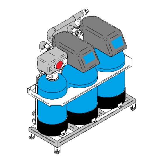
- Page 1 USE AND INSTALLATION MANUAL SOFTENER MODULE - KITWSRT [Type here] Doc. No. xx Edition 0.1.00 – 02/2019...
- Page 2 All the images and information in this manual belong to ©Electrolux Professional Spa. This document and its contents cannot be copied or used, in part or as a whole, without the authorisation of Electrolux Professional Spa. ©Electrolux Professional Spa. All rights reserved...
- Page 3 The manual must always be part of the documentation made available when the machine is being used and must...
- Page 4 This manual must be carefully stored for future consultation and is considered an integral part of the machinery. It must be transferred with the machinery if sold and/or relocated. MODELS COVERED BY THIS MANUAL MODEL DESCRIPTION TYPE VOLTAGE KITWSRT SOFTENER MODULE ELECTRIC 230/1N/50Hz...
-
Page 5: Table Of Contents
USE AND INSTALLATION MANUAL TABLE OF CONTENTS 1. GENERAL INFORMATION ..........................7 1.1. PURPOSE AND CONTENTS ........................7 1.2. SAFETY INFORMATION AND PRECAUTIONS ..................7 1.2.1. PERSONAL PROTECTIVE EQUIPMENT .................... 9 1.2.2. GENERAL INFORMATION ........................9 1.2.3. RESIDUAL RISKS ..........................10 1.3. - Page 6 USE AND INSTALLATION MANUAL 4.2.4. MANUAL REGENERATION ........................ 39 5. TROUBLESHOOTING ............................40 5.1. COLD WATER PART ..........................40 5.1.1. TROUBLESHOOTING THE VALVE ....................40 5.1.2. TIMER TROUBLESHOOTING ......................40 5.2. HOT WATER PART ........................... 41 5.3. SALT STORAGE SKID ..........................42 6.
-
Page 7: General Information
USE AND INSTALLATION MANUAL 1. GENERAL INFORMATION 1.1. PURPOSE AND CONTENTS The purpose of this manual is to provide the user, who already has basic technical knowledge, with all the specific information required to operate the machine autonomously under normal circumstances. It refers to information about the operation and routine maintenance included in the technical manual. - Page 8 USE AND INSTALLATION MANUAL Only specialised personnel are authorised to operate the machine. Dispose of the packaging of the parts and any bags or boxes responsibly. Any parts that are replaced must be disposed of in accordance with current regulations. DANGER! The tasks described in this manual are reserved for specialised personnel, authorised by the manufacturer, to perform them in compliance with the regulations in force in the country of use and the relevant system and work safety standards.
-
Page 9: Personal Protective Equipment
USE AND INSTALLATION MANUAL 1.2.1. PERSONAL PROTECTIVE EQUIPMENT Table summarising the personal protective equipment (PPE) to be used during the various stages of the machine’s life cycle. Part Protective clothing Safety footwear Gloves Glasses Helmet replaced ● ○ Pump motor ●... -
Page 10: Residual Risks
USE AND INSTALLATION MANUAL 1.2.3. RESIDUAL RISKS Using the machine involves some risks which cannot be completely eliminated through design or with the installation of adequate protective devices. However, the manufacturer has undertaken to inform the operators of these risks in this manual by specifically indicating the personal protective equipment to use. When repairing the machine, adequate space has been provided to limit these risks. -
Page 11: Label
USE AND INSTALLATION MANUAL Safety signage to be placed near the machine Prohibition Meaning Do not remove the safety devices. Do not use water to extinguish fires (located on electrical parts). Keep the area around the machine clean and free from combustible materials. -
Page 12: Identification Plate - Cold Water Mixer Head
USE AND INSTALLATION MANUAL 1.3.1. IDENTIFICATION PLATE - COLD WATER MIXER HEAD The identification label can be found under the side of the control panel. The meaning of the various information is listed below: F.Mod. Factory model description Comm.Mode Commercial description Production numeric code Ser.No Serial number... -
Page 13: Skid Specifications
USE AND INSTALLATION MANUAL 1.4. SKID SPECIFICATIONS 1.4.1. OVERALL EXTERNAL DIMENSIONS COLD WATER OUTLET COLD WATER INLET HOT WATER OUTLET HOT WATER INLET DRAIN OUTLET The maximum dimensions are indicated in millimetres and do not include hydraulic and electrical connections. -
Page 14: General Technical Characteristics
USE AND INSTALLATION MANUAL 1.4.2. GENERAL TECHNICAL CHARACTERISTICS SOFTENERS SKID TECHNICAL SPECIFICATIONS Width x Depth x Height (mm) 830X510x720 Weight (kg) CHARACTERISTICS OF THE WATER SUPPLY Type of cold water Potable Type of hot water Potable Minimum cold water temperature (°C) Maximum cold water temperature (°C) Minimum hot water temperature (°C) Maximum hot water temperature (°C) -
Page 15: By-Pass Valve
USE AND INSTALLATION MANUAL SPECIFICATIONS / DESIGN CLASS Valve body.................Noryl glass fibre® - List NSF material Rubber components ......... Cold water components - List NSF material Certification of valve material ...WQA Gold Seal Certified to ORD 0902, NSF/ANSI 44, CE Weight (valve with controller) .................. -
Page 16: Technical Characteristics - Hot Water Mixing Heads
USE AND INSTALLATION MANUAL 1.4.5. TECHNICAL CHARACTERISTICS - HOT WATER MIXING HEADS MODEL 12 LITRES/TIME 10”x17’’ CYLINDER SET SALT ADJUSTMENT 1.8 Kg INJECTOR DLFC BLFC SPECIFICATIONS / DESIGN CLASS Valve body Brass Rubber components EP or EPDM Weight (valve with controller). 2.5 kg Recommended MIN - MAX working pressure 1.4 - 8.6 bar... -
Page 17: General Dimensions - Salt Storage Skid
USE AND INSTALLATION MANUAL 1.4.6. GENERAL DIMENSIONS – SALT STORAGE SKID KEY: A_SALT VAT COLD WATER SOFTENER B_SALT VAT COLD WATER SOFTENER C_SALT VAT HOT WATER SOFTENER 1.4.7. TECHNICAL SPECIFICATIONS BRINE SKID TECHNICAL SPECIFICATIONS Width x Depth x Height (mm) 800x1100x855 Weight (kg) CHARACTERISTICS OF THE WATER SUPPLY... -
Page 18: Installation And Start-Up
USE AND INSTALLATION MANUAL 2. INSTALLATION AND START-UP 2.1. INSTALLATION The machine must be installed in a dry, suitably hygienic and well-ventilated area where adequate precautions have been taken to protect it from sub-zero temperatures and/or heated components and direct sunlight. Consider an area protected from routine processing or cleaning operations in order to protect the system from being accidentally sprayed with water. -
Page 19: Installation - Salt Storage Skid
USE AND INSTALLATION MANUAL 2.1.1. INSTALLATION – SALT STORAGE SKID Position the skid taking the requirements given below into account: • Easily accessible and salt refill position; • Flat and stable position; • Maximum distance from softeners equal to 2 metres positioned on the same support surface as the latter;... -
Page 20: Electrical Connections
USE AND INSTALLATION MANUAL 2.1.2. ELECTRICAL CONNECTIONS Connect the general power plug of the ES control panel of skid 1 to a single-phase electrical power outlet. Connect the skid 2 salt deposit from the EO board to the ES board of the skid 1 (see points 3-4 of the connection diagram) GENERAL INFORMATION The machine must be connected to an earthed power outlet. -
Page 21: Start-Up
USE AND INSTALLATION MANUAL 2.2. START-UP 2.2.1. STARTING THE SOFTENERS: COLD WATER PART 2.2.1.1. AIR VENT WARNING: During the first start-up, the ‘ERROR’ message may be displayed, in this case the timers will automatically search for the service position and the message will appear when the system is in phase. A- Put 10 litres of untreated water ONLY in each of the three ‘brine salt’... - Page 22 USE AND INSTALLATION MANUAL 1. Close the water supply or insert the by- pass valve/s. 2. Depressurise the system by manually starting extra regeneration disconnecting the timer from the power supply. 3. Remove the four screws and nuts which secure the turbine fitting to the by-pass valve or the pipes.
-
Page 23: Starting The Softeners: Hot Water Part
USE AND INSTALLATION MANUAL 2.2.2. STARTING THE SOFTENERS: HOT WATER PART Starting the softener • Slowly open the inlet valve. • Turn knob A to the backwash position (red light on) and let it flow for a few minutes or until the system feeds water without any air to the drain. -
Page 24: Starting The Salt Storage Skid
USE AND INSTALLATION MANUAL 2.2.3. STARTING THE SALT STORAGE SKID Before starting the softeners: -Add untreated water until the extraction filter (A) is covered, about 10 litres; -Remove the floats and fill with salt; -Place the floats vertically at the top and position them horizontally on the salt. CAUTION USE GOOD QUALITY SALT WITH NO EARTH RESIDUE. -
Page 25: Machine Description
USE AND INSTALLATION MANUAL 3. MACHINE DESCRIPTION 3.1. COLD WATER OPERATING LOGIC The softeners fitted with a Logix control valve have nine operating cycles. The softening system consists of two control valves, two cylinders containing strong cation resin in sodium cycle, connected to one another to form a continually flowing system which operates with a duplex alternator logic and of two brine vats on a separate brine system skid. -
Page 26: Hot Water Operating Logic
USE AND INSTALLATION MANUAL System pause position (repressurization) The system goes into stand-by, pressurising the cylinder. Waiting position The regeneration process is interrupted whilst waiting for the cylinder in service to run out. Quick rinse 1 position The water flows through the resin and rises up via the central pipe, flowing towards the drain. The residual brine is thus eliminated. - Page 27 USE AND INSTALLATION MANUAL with sodium ions. As the water passes through the resin bed, it is conditioned. Backwash - C1 cycle The water flow is reversed by the valve and sent downwards along the rising pipe and upwards through the resin bed.
-
Page 28: Operating Logic
USE AND INSTALLATION MANUAL 3.3. OPERATING LOGIC When the first minimum level for the salt is reached, the float is in a vertical position (fig a) and triggers a light indicator in the control panel. Remove the float completely and after filling and restoring the correct salt level, it must be briefly placed upright before being reinserted (fig b). -
Page 29: Routine Check Plan
USE AND INSTALLATION MANUAL 3.4. ROUTINE CHECK PLAN 3.4.1. PREVENTIVE CHECKS A series of visual and operational inspections aimed at checking the correct operation and performance of the skid. The preventive checks allow the components, subject to consumption or wear, to be identified through preventive checks and replaced as indicated in the following paragraphs and in the section entitled Error! Reference source not found.. -
Page 30: Unscheduled Maintenance Work
USE AND INSTALLATION MANUAL 3.4.3. UNSCHEDULED MAINTENANCE WORK PART TO BE CHECKED CHECK FREQUENCY Basic calibration Functional test 3 MONTHS Functional test Functional test 3.4.4. RECOMMENDATIONS Use original spare parts To ensure the device works correctly safely, only use the original spare parts and accessories recommended by the manufacturer. -
Page 31: Control Panel
USE AND INSTALLATION MANUAL 4. CONTROL PANEL 4.1. COLD WATER TIMER PROGRAMMING When installation has been completed, programming must be performed before starting up the softener. 4.1.1. TIMER CHARACTERISTICS LCD display DOWN button SET button UP button Start regeneration button 740/760, Turbine inlet Main motor connection and optical sensor Adaptor inlet for electrical current... -
Page 32: Timer Display
USE AND INSTALLATION MANUAL 4.1.2. TIMER DISPLAY 1 Days of the week. The flag under the day indicates the day of the current week. 5 "PM" indicates whether the time shown is between midday and midnight (there is no AM indicator). The PM indicator is not used if the clock is set to 24 hours. -
Page 33: Service Indications Display
USE AND INSTALLATION MANUAL 4.1.3. SERVICE INDICATIONS DISPLAY The current time and cubic metres It indicates a supply interruption and requires the available before the supply runs out are current time to be reprogrammed (see 4.6, point displayed alternately. The tap symbol is displayed, indicating that In this condition, the softener cannot generate water is being supplied to the service softened water. -
Page 34: Regeneration Mode
USE AND INSTALLATION MANUAL 4.1.4. REGENERATION MODE When in stand-by, the display shows the current time and day of the week. During regeneration, the time indicates the operating phase (C1÷C8) and the regeneration time remaining. Delayed regeneration Press the REGEN button, the programmer will perform a regeneration at the next set regeneration time (at 2:00 by default). -
Page 35: Timer Programming
USE AND INSTALLATION MANUAL 4.1.6. TIMER PROGRAMMING Initial switch-on When first switched on, the camshaft must turn to the starting position (in service). It may take 1-2 minutes for the camshaft to position itself in the starting position. Err 3 will be displayed until the camshaft is in the starting position. If more than 2 minutes pass, check that the motor is turning the camshaft. - Page 36 USE AND INSTALLATION MANUAL Phase 5: Set safety regeneration frequency Set the number of days for the safety regeneration frequency even when the cycle has not finished. “0” days is the default value. The days can be adjusted from 1/2 day (0.5) to 99 days. To modify, press SET to make the “0”...
-
Page 37: Hot Water Timer Programming
USE AND INSTALLATION MANUAL 4.2. HOT WATER TIMER PROGRAMMING 4.2.1. CHARACTERISTICS: TIMED 24 hour wheel Programming wheel Defines the number of days between two regenerations Time of day Shows current time Service position Service Regeneration Backwash Brine extraction/Slow wash Brine tank filling Red light Turns on when the valve is regenerated Green light... -
Page 38: Procedure
USE AND INSTALLATION MANUAL 4.2.2. PROCEDURE Regeneration takes place at 2 am in the morning. 4.2.3. SERVICE INDICATIONS DISPLAY The positions appear in window A of the dial during regeneration During service Example: valve in service: During regeneration During regeneration, the current cycle is displayed. Examples: •... -
Page 39: Manual Regeneration
USE AND INSTALLATION MANUAL 4.2.4. MANUAL REGENERATION Instant regeneration Ref. Procedure Turn the control button (3) until appears in the window (2) and the red light (1) turns on. Operation during supply interruption • When supply is interrupted, the valve stops in the current position with the indicator lights turned off. •... -
Page 40: Troubleshooting
USE AND INSTALLATION MANUAL 5. TROUBLESHOOTING Before running the checks listed in the event of operating faults, do the following: Make sure that the inlet valve is open; Make sure that the supply pressure is within the specified ranges; Make sure that the power socket is adequate; Make sure the thermal protection is armed;... -
Page 41: Hot Water Part
USE AND INSTALLATION MANUAL 5.2. HOT WATER PART Problem: THE SOFTENER IS NOT AUTOMATICALLY REGENERATING Cause Solution Power interrupted or power Reset the controller and connect a constant power supply. source switched off. Faulty motor Replace the motor Faulty controller Replace the controller Incorrect programming Program correctly... -
Page 42: Salt Storage Skid
USE AND INSTALLATION MANUAL Cause Solution Foreign matter in the valve Clean the valve and check it in different regeneration positions Inner valve leak Valve blocked during brine tank Replace the seal and spacer and/or piston unit filling or backwash Faulty or blocked motor Replace the motor and check the gear teeth The control head is nor working... -
Page 43: Disposal Of Consumables And Machine
USE AND INSTALLATION MANUAL 6. DISPOSAL OF CONSUMABLES AND MACHINE The used filters are considered non-hazardous solid waste to be disposed of with code EWC 19.09.04 (active carbon) and the membranes with code EWC 15.02.03. At the end of its life, the machine must be disposed of at an authorised dismantling and disposal centre (EWC 20.01.36). - Page 45 Electrolux Professional S.p.A. Viale Treviso, 15 33170 Pordenone, ITALY www.electrolux.com/professional...