Table of Contents
Advertisement
Available languages
Available languages
Quick Links
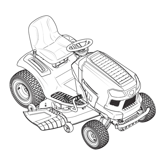
Operator's Manual
Turn Tight® Extreme Rider
24 HP, 46" MOWER DECK
Model No. 247.204420
• Espanol, P. 35
THIS product has a low emission engine which operates differently from
previously built engines. Before you start the engine, read and understand
this Operator's Manual.
CAUTION
Before using this equipment,
read this manual and follow
all safety rules and operating
instructions.
Sears Brands Management Corporation, Hoffman Estates, IL 60179 U.S.A.
Visit our website: www.craftsman.com
For answers to your questions about
this product, call:
1-888-331-4569
Customer Care Hot Line
Form No. 769-10491
(March 9, 2015)
Advertisement
Table of Contents

Related Manuals for Craftsman PRO Turn Tight 247.204420


Summary of Contents for Craftsman PRO Turn Tight 247.204420
- Page 1 Before using this equipment, 1-888-331-4569 read this manual and follow all safety rules and operating Customer Care Hot Line instructions. Sears Brands Management Corporation, Hoffman Estates, IL 60179 U.S.A. Visit our website: www.craftsman.com Form No. 769-10491 (March 9, 2015)
-
Page 2: Table Of Contents
With proof of purchase, you will receive a new cast iron front axle at no charge. WARRANTY SERVICE For warranty coverage details to obtain free repair or replacement, visit the web page: www.craftsman.com/warranty Product Replacement If part repair or replacement is impossible, you will receive a new riding equipment unit of the same or equivalent model. -
Page 3: Safety Instructions
SAFETY INSTRUCTIONS WARNING DANGER This symbol points out important safety instructions which, if not This machine was built to be operated according to the safe operation followed, could endanger the personal safety and/or property of practices in this manual. As with any type of power equipment, yourself and others. - Page 4 SAFETY INSTRUCTIONS Do Not: • Check overhead clearances carefully before driving under low hanging tree branches, wires, door openings etc., where the operator may be struck or • Do not turn on slopes unless necessary; then, turn slowly and gradually pulled from the machine, which could result in serious injury.
- Page 5 SAFETY INSTRUCTIONS • On slopes, the weight of the towed equipment may cause loss of traction and • Periodically check to make sure the blades come to complete stop within loss of control. approximately (5) five seconds after operating the blade disengagement control.
- Page 6 SAFETY INSTRUCTIONS DO NOT MODIFY ENGINE SPARK ARRESTOR To avoid serious injury or death, do not modify engine in any way. Tampering WARNING with the governor setting can lead to a runaway engine and cause it to operate at unsafe speeds. Never tamper with factory setting of engine This machine is equipped with an internal combustion engine and should governor.
- Page 7 SAFETY INSTRUCTIONS Symbol Description DANGER — SAFETY DEVICES Keep safety devices (guards, shields, switches, etc . ) in place and working . BYSTANDERS Keep bystanders, helpers, children and pets at least 75 feet from the machine while it is in operation .
-
Page 8: Slope Guide
SLOPE GAUGE... -
Page 9: Assembly
ASSEMBLY Install Operator’s Seat (If necessary) NOTE: All references in this manual to the left or right side and front or back of the tractor are from the operating position only. Exceptions, if any, will be specified. To install the seat proceed as follows: Tractor Preparation NOTE: The seat is shipped with the seat switch and seat pan attached. - Page 10 ASSEMBLY Lower Deck Discharge Chute Deflector Rotate the seat into position and secure the seat into place with the previously removed shoulder screws and flange lock nuts. Be careful not to WARNING crimp or damage the wire harness while installing the seat. See Figure 3. Never operate the mower deck without the chute deflector installed and in the down position.
- Page 11 ASSEMBLY Adjusting the Seat Remove the plastic cover, if present, from the positive battery terminal and attach the red cable to the positive battery terminal (+) with the bolt and WARNING hex nut. See Figure 8. Before operating the tractor, make sure the seat is engaged in the seat- stop.
- Page 12 ASSEMBLY Gas & Oil Check the wheels for contact or excessive clearance with the surface below. The deck wheels should have between ¼” and ½” clearance above the The fuel tank is located at the outer/left of the dash and holds 3 gallons of gas. ground.
-
Page 13: Operation
OPERATION Fuel Tank Cap Throttle/Choke Hour Meter Control Lever Ignition Module Forward Drive Pedal PTO Switch Reverse Drive Pedal Brake Pedal Park Brake/Cruise Control Lever Storage Tray Deck Lift Lever Cup Holder Seat Adjustment Lever Transmission Bypass Rod Figure 10 Reverse Drive Pedal Now that you have set up your riding mower, it’s important to become acquainted with its controls and features. - Page 14 OPERATION Throttle/Choke Control Lever Transmission Bypass Rod The throttle/choke control lever is located on the left side of the The transmission bypass rod is located at the rear of the tractor on the lower right tractor’s dash panel. This lever controls the speed of the engine and, section of the frame.
- Page 15 OPERATION Low Battery Starting the Engine At startup, the battery voltage is briefly displayed then changes to accumulated WARNING hours. The letters “LO” will display followed by the letters “BATT” and then followed Do not operate the tractor if the interlock system is malfunctioning. This by the meter’s accumulated time.
- Page 16 OPERATION Reverse Caution Mode Driving The Tractor The REVERSE CAUTION MODE position of the ignition module allows the WARNING tractor to be operated in reverse with the blades (PTO) engaged. Avoid sudden starts, excessive speed and sudden stops. NOTE: Mowing in reverse is not recommended. Lightly press the brake pedal to release the parking brake.
- Page 17 OPERATION Driving On Slopes To disengage the cruise control, lightly press the forward drive pedal or the brake pedal. Refer to the SLOPE GAUGE on page 8 to help determine slopes where you may NOTE: Cruise control can not be set at the tractor’s fastest ground speed. operate the tractor safely.
- Page 18 OPERATION Mowing WARNING Make certain the area to be mowed is free of debris, sticks, stones, wire or other objects that can be thrown by the rotating blades. NOTE: Do not engage the mower deck when lowered in grass. Premature wear and possible failure of the belt and PTO clutch will result.
-
Page 19: Service And Maintenance
SERVICE AND MAINTENANCE MAINTENANCE SCHEDULE Follow the maintenance schedule given below. This chart describes service guidelines WARNING only. Use the Service Log column to keep track of completed maintenance tasks. To schedule service from Sears Parts & Repair, call 1-888-331-4569. Before performing any type of maintenance/service, disengage all controls and stop the engine. - Page 20 SERVICE AND MAINTENANCE NOTE: This Operator’s Manual covers several models. Tractor features may vary by Place an appropriate oil collection container with at least a 2.5 quart capacity model. Not all features in this manual are applicable to all tractor models and the below the opening of the oil drain tube, to collect the used oil.
- Page 21 SERVICE AND MAINTENANCE Cleaning the Tractor After cleaning your deck with the Smart Jet system, return to the operator’s position and engage the PTO. Keep the cutting deck running for a minimum of Any fuel or oil spilled on the machine should be wiped off promptly. Do NOT allow two minutes, allowing the underside of the cutting deck to thoroughly dry.
- Page 22 SERVICE AND MAINTENANCE Deck Wheels To lower the front of the deck, loosen the outer nut then loosen (thread outward) the nut, away from the front hanger bracket. See Figure 18. When The wheels on the front of the deck are equipped with a grease fitting. Lubricate proper adjustment is achieved, re-tighten the outer nut.
- Page 23 SERVICE AND MAINTENANCE Jump Starting Measure the distance from the outside of the left blade tip to the ground and the distance from the outside of the right blade tip to the ground. Both WARNING measurements taken should be 4”. If they’re not, proceed to the next step. Never jump start a damaged or frozen battery.
- Page 24 SERVICE AND MAINTENANCE Fuse Looking at the cutting deck from the left side of the tractor, locate the bow- tie pin on the rear left side of the deck. See Figure 21. WARNING Before servicing, repairing, or inspecting, always disengage PTO, set parking brake, stop engine and remove key to prevent unintended starting.
- Page 25 SERVICE AND MAINTENANCE Cutting Blades To properly sharpen the cutting blades, remove equal amounts of metal from both ends of the blades along the cutting edges, parallel to the trailing edge, at a 25°- to 30° angle. Always grind each cutting blade edge equally to WARNING maintain proper blade balance.
- Page 26 SERVICE AND MAINTENANCE Loosen, but do not remove the flange lock nut on the right idler pulley and Retighten idler pulleys. the hex screw on the left idler pulley. See Figure 25. Remount the spindle covers if removed after step 1. Re-install the deck making sure the belt remains routed around the pulleys as instructed.
-
Page 27: Off-Season Storage
OFF-SEASON STORAGE WARNING Never store garden riding mower with fuel in tank indoors or in poorly ventilated areas where fuel fumes may reach an open flame, spark, or pilot light as on a furnace, water heater, clothes dryer, or gas appliance. Off-Season Storage Lubricate all lubrication points. -
Page 28: Troubleshooting
TROUBLESHOOTING WARNING Before performing any type of maintenance/service, disengage all controls and stop the engine. Wait until all moving parts have come to a complete stop. Disconnect spark plug wire and ground it against the engine to prevent unintended starting. Always wear safety glasses during operation or while performing any adjustments or repairs. - Page 29 TROUBLESHOOTING Engine overheats Engine oil level low Fill engine with proper amount and type of oil. Air flow restricted Clean grass clippings and debris from around the engine’s cooling fins and blower housing. Engine hesitates at high RPMs 1. Spark plug gap set too close Remove spark plug and adjust gap.
- Page 30 NOTES...
- Page 31 (This page applicable in the U.S.A. and Canada only.) Sears Brands Management Corporation (Sears), the California Air Resources Board (CARB) and the United States Environmental Protection Agency (U.S. EPA) Emission Control System Warranty Statement (Owner’s Defect Warranty Rights and Obligations) EMISSION CONTROL WARRANTY COVERAGE IS APPLICABLE TO CERTIFIED ENGINES AND TO CERTIFIED MODEL YEAR 1997 AND LATER ENGINES WHICH ARE PURCHASED AND PURCHASED IN CALIFORNIA IN 1995 AND THEREAFTER, WHICH ARE USED IN CALIFORNIA,...
- Page 32 FEDERAL and/or CALIFORNIA EMISSION CONTROL WARRANTY STATEMENT YOUR WARRANTY RIGHTS AND OBLIGATIONS MTD Consumer Group Inc, the United States Environmental Protection Agency (EPA), and for those products certified for sale in the state of California, the California Air Resources Board (CARB) are pleased to explain the evaporative emission control system (ECS) warranty on your 2014-2015 small off-road equipment (outdoor equipment) .
- Page 33 WARRANTED PARTS: The repair or replacement of any warranted part otherwise eligible for warranty coverage may be excluded from such warranty coverage if MTD Consumer Group Inc demonstrates that the outdoor equipment has been abused, neglected, or improperly maintained, and that such abuse, neglect, or improper maintenance was the direct cause of the need for repair or replacement of the part .
- Page 34 REPAIR PROTECTION AGREEMENT Congratulations on making a smart purchase. Your new Craftsman® product is designed and manufactured for years of dependable operation. But like all products, it may require repair from time to time. That’s when having a Repair Protection Agreement can save you money and aggravation.
-
Page 35: Español
Con la prueba de compra, recibirás un nuevo eje delantero de hierro fundido en forma gratuita. SERVICIO DE GARANTÍA Para detalles de la cobertura de la garantía para obtener la reparación o sustitución gratuita, visite la página web: www.craftsman.com/warranty Reemplazo del producto Si es imposible la reparación o el reemplazo parte, recibirá... - Page 36 INSTRUCCIONES DE SEGURIDAD ADVERTENCIA PELIGRO La presencia de este símbolo indica que se trata de instrucciones de seguridad Esta máquina está diseñada para ser utilizada respetando las normas de importantes que debe respetar para evitar poner en riesgo su seguridad seguridad contenidas en este manual.
- Page 37 INSTRUCCIONES DE SEGURIDAD No haga lo siguiente: • El silenciador y el motor se calientan y pueden causar quemaduras. No los toque. • No gire en pendiente a menos que sea necesario; si lo hace, gire lenta y • Revise la holgura superior antes de conducir debajo de ramas bajas, cables, gradualmente cuesta abajo, si es posible.
- Page 38 INSTRUCCIONES DE SEGURIDAD • En las pendientes, el peso del equipo remolcado puede causar pérdida de tracción • Controle periódicamente para asegurarse que las cuchillas se detienen y pérdida de control. completamente aproximadamente cinco (5) segundos después de accionar el control de desacople.
- Page 39 INSTRUCCIONES DE SEGURIDAD NO MODIFIQUE EL MOTOR AMORTIGUADOR DE CHISPAS Para evitar lesiones graves o la muerte, no modifique el motor de ninguna manera. ADVERTENCIA Si altera la configuración del regulador, el motor se puede desbocar y funcionar a velocidades que no son seguras. Nunca cambie la configuración de fábrica del Esta máquina está...
- Page 40 INSTRUCCIONES DE SEGURIDAD Símbolo Descripción PELIGRO — DISPOSITIVOS DE SEGURIDAD Mantenga los dispositivos de seguridad (guardas, protectores, interruptores, etc . ) en su lugar y funcionando . OBSERVADORES Mantenga a los observadores, ayudantes, mascotas y niños por lo menos a 75 pies (23 m . ) de la máquina mientras está...
- Page 41 INDICADOR DE PENDIENTE...
- Page 42 MONTAJE Instale el asiento del operador (si corresponde) NOTA: Las referencias que contiene este manual sobre los lados derecho o izquierdo y trasero o delantero del tractor se hacen siempre desde la posición de operación. Las Para instalar el asiento proceda de la siguiente manera: excepciones, si las hubiere, serán especificadas.
- Page 43 MONTAJE Baje el deflector del canal de descarga de la plataforma Gire el asiento hasta la posición deseada y asegúrelo en su lugar con los tornillos de reborde y las tuercas de seguridad con brida que extrajo antes. Tenga cuidado de ADVERTENCIA no doblar o dañar el cableado mientras instala el asiento.
- Page 44 MONTAJE Ajuste del asiento Retire la cubierta plástica, si es que está presente, del borne positivo de la batería y una el cable rojo al borne positivo de la batería (+) utilizando el perno y la tuerca ADVERTENCIA hexagonal. Vea la Figura 8. Antes de hacer funcionar el tractor, compruebe que el asiento está...
- Page 45 MONTAJE Gasolina y aceite Controle si las ruedas están en contacto con la superficie de abajo o si hay excesiva separación. Las ruedas de la plataforma deben tener entre ¼ y ½ pulgada de El depósito de combustible se encuentra en la parte exterior/izquierda del tablero y separación respecto del suelo.
- Page 46 FUNCIONAMIENTO Tapón del depósito de combustible Medidor horario Palanca de control del Módulo de encendido acelerador/cebador Pedal de marcha adelante PTO Switch Pedal de marcha atrás Pedal de freno Palanca del freno de de mano/control de crucero Bandeja de almacenamiento Palanca de elevación de la plataforma Portavasos Palanca de ajuste del asiento...
- Page 47 FUNCIONAMIENTO Palanca de control del acelerador/cebador Varilla de derivación de la transmisión La varilla de derivación de la transmisión se encuentra en la parte trasera del tractor en la La palanca de control del acelerador/cebador está ubicada del lado izquierdo sección inferior derecha del bastidor.
- Page 48 FUNCIONAMIENTO Poca batería Encendido del motor Al arrancar, se visualiza fugazmente el voltaje de la batería y luego cambia a horas ADVERTENCIA acumuladas. Aparecen las letras “LO” (poco), seguidas de las letras “BATT” (batería), No opere el tractor si el sistema de interbloqueo funciona mal. El sistema fue seguidas luego del tiempo acumulado del medidor.
- Page 49 FUNCIONAMIENTO Modo marcha atrás con precaución Conducción del tractor ADVERTENCIA La posición MODO MARCHA ATRÁS CON PRECAUCIÓN del módulo de encendido permite operar el tractor marcha atrás con la (PTO) de las cuchillas activada. Evite arrancar súbitamente, desarrollar excesiva velocidad y detenerse de NOTA: No se recomienda cortar el césped en marcha atrás.
- Page 50 FUNCIONAMIENTO Operación en pendientes Para desactivar el control de crucero, presione suavemente el pedal de marcha adelante o el pedal de freno. Consulte la sección INDICADOR DE PENDIENTE en la página 8 para determinar en qué NOTA: El control de crucero no se puede fijar en la velocidad absoluta más pendientes puede operar el tractor de manera segura.
- Page 51 FUNCIONAMIENTO Corte de césped ADVERTENCIA Asegúrese de que el área donde se va a cortar esté libre de desechos, ramitas, piedras, cables u otros objetos que puedan ser arrojados por las cuchillas rotativas. NOTA: No enganche la plataforma de corte cuando esté baja sobre el pasto. Se produce el desgaste prematuro y la posible falla de la correa y del embrague de la PTO.
- Page 52 SERVICIO Y MANTENIMIENTO PROGRAMA DE MANTENIMIENTO Siga el cronograma de mantenimiento que se presenta a continuación. En esta tabla ADVERTENCIA sólo describen pautas de servicio. Utilice la columna Registro de Servicio para hacer el Antes de realizar cualquier tipo de mantenimiento o servicio, desactive todos los seguimiento de las tareas de mantenimiento completadas.
- Page 53 SERVICIO Y MANTENIMIENTO NOTA: Este manual de operación cubre distintos modelos. Las características del tractor Para recoger el aceite usado, coloque un recipiente adecuado para recolectar el pueden variar según los modelos. No todas las características que se incluyen en este aceite, con al menos una capacidad de 2.5 cuartos de galón, debajo de la abertura manual se aplican a todos los modelos de tractor y la máquina que se ilustra aquí...
- Page 54 SERVICIO Y MANTENIMIENTO Limpieza del tractor Después de limpiar la plataforma con el sistema Smart Jet, regrese a la posición del operador y conecte la PTO. Mantenga la plataforma de corte en funcionamiento Si se derrama combustible o aceite sobre la máquina, debe limpiarse de inmediato. durante dos minutos por lo menos para permitir que se seque totalmente la parte NO permita que se acumulen desechos alrededor de las aletas de refrigeración del motor, inferior de la misma.
- Page 55 SERVICIO Y MANTENIMIENTO Ruedas de la plataforma Para bajar el frente de la plataforma, afloje la tuerca exterior y luego afloje (rosca hacia afuera) la tuerca, alejándola del soporte de suspensión delantera. Consulte la Las ruedas de adelante de la plataforma están equipadas con dispositivo de engrase. Figura 18.
- Page 56 SERVICIO Y MANTENIMIENTO Arranque con cables de puente Mida la distancia desde la parte externa de la punta de la cuchilla izquierda hasta el piso, y desde la parte externa de la punta de la cuchilla derecha hasta el piso. ADVERTENCIA Las dos mediciones obtenidas deben ser 4 pulgadas.
- Page 57 SERVICIO Y MANTENIMIENTO Fusible Mirando hacia la plataforma de corte desde el lado izquierdo del tractor, ubique el pasador de chaveta en el lado posterior izquierdo de la plataforma. Vea la Figura 21. ADVERTENCIA Antes de hacer el servicio, reparar o inspeccionar, siempre desactive la PTO, ponga el freno de mano, pare el motor y retire la llave, para evitar el arranque accidental.
- Page 58 SERVICIO Y MANTENIMIENTO Cuchillas de corte Para afilar las cuchillas de corte de forma adecuada, extraiga cantidades iguales de metal de ambos extremos de las cuchillas a lo largo de los bordes cortantes, paralelo al borde de caída y a un ángulo de 25° a 30°. Afile siempre ADVERTENCIA cada borde de las cuchillas de corte de forma pareja para mantener un Apague el motor y extraiga la llave de contacto antes de retirar las cuchillas...
- Page 59 SERVICIO Y MANTENIMIENTO Afloje, pero no quite la tuerca de seguridad con brida de la polea loca derecha y el Vuelva a ajustar las poleas locas. tornillo hexagonal de la polea izquierda. Vea la Figura 25. Vuelva a montar las cubiertas de los husillos se fueron retiradas después del paso 1.
- Page 60 ALMACENAMIENTO FUERA DE TEMPORADA ADVERTENCIA Nunca almacene el tractor cortacésped con combustible en el tanque en un espacio cerrado o en áreas poco ventiladas donde los gases del combustible puedan llegar a una llama expuesta, una chispa o un piloto como el que tienen algunos hornos, calentadores de agua, secadores de ropa o algún artefacto a gas.
- Page 61 SOLUCIÓN DE PROBLEMAS ADVERTENCIA Antes de realizar cualquier tipo de mantenimiento o servicio, desac- tive todos los controles y detenga el motor. Espere a que se detengan completamente todas las piezas móviles. Desconecte el cable de la bujía y póngalo haciendo masa contra el motor para evitar que se encienda accidentalmente.
- Page 62 SOLUCIÓN DE PROBLEMAS El motor funciona de manera La unidad está funcionando con el cebador Compruebe que el cebador eléctrico funcione. errática activado. Comuníquese con Sears u otro distribuidor de servicio calificado. Los cables de bujía están flojos. Conecte y ajuste los cables de la bujía. La línea del combustible está...
- Page 63 NOTAS...
- Page 64 (Esta página se aplica sólo en EE.UU. y Canadá). Sears Brands Management Corporation, el Consejo de Recursos Ambientales de California (CARB) y la Agencia de Protección Ambiental de los Estados Unidos (EPA) Declaración de garantía del sistema de control de emisiones (derechos y obligaciones de la garantía de defectos del propietario) LA COBERTURA DE LA GARANTÍA DE CONTROL DE EMISIONES ES APLICABLE A LOS MOTORES Y UTILICEN EN CUALQUIER PARTE DE LOS ESTADOS UNIDOS (Y A PARTIR DEL 1 DE ENERO DE 2001 EN...
- Page 65 DECLARACIÓN FEDERAL y/o DE CALIFORNIA SOBRE GARANTÍAS EN EL CONTROL DE EMISIONES SUS DERECHOS Y OBLIGACIONES EN CUANTO A LA GARANTÍA MTD Consumer Group Inc, la Agencia de Protección Medioambiental de los Estados Unidos (EPA), y para aquellos productos certificados para su venta en el estado de California, el Departamento de los Recursos del Aire de California (CARB) se complacen en explicar la garantía que evaporativo sistema de control de emisiones (ECS) de su equipo (equipos de exteriores) de encendido por chispa para todo terreno, pequeño, de exteriores del año 2014-2015 .
- Page 66 Durante la totalidad del período de garantía del motor y equipo para todo terreno arriba mencionado, MTD Consumer Group Inc mantendrá un suministro de piezas bajo garantía suficiente para satisfacer la demanda esperada de tales piezas . Cualquier pieza de reemplazo se podrá usar para el cumplimiento del mantenimiento o las reparaciones bajo garantía y se suministrarán sin cargo para el propietario .
- Page 67 REPAIR PROTECTION AGREEMENT Felicitaciones por haber realizado una adquisición inteligente. El producto Craftsman® que ha adquirido está diseñado y fabricado para brindar muchos años de funcionamiento confiable. Pero como todos los productos a veces puede requerir de reparaciones. Es en ese momento cuando el disponer de un Acuerdo de protección para reparaciones le puede ahorrar dinero y problemas.
- Page 68 Para respuestas a preguntas o problemas, y ordenar piezas o pedir servicio para la reparación de su equipo. To help us help you, register your product at www.craftsman.com/registration Para poderte ayudar mejor, registra tu producto en www.craftsman.com/registration Join the Craftsman Club today!