Table of Contents
Advertisement
Quick Links
Advertisement
Table of Contents

Related Manuals for Casio WK-240


Summary of Contents for Casio WK-240
- Page 1 WK-240 JUN. 2014 Ver. 1 : Jul. 2014...
-
Page 2: Table Of Contents
WK-240 CONTENTS SPECIFICATIONS ..........1 BLOCK AND WIRING DIAGRAM . -
Page 3: Specifications
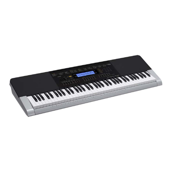
WK-240 SPECIFICATIONS Keyboard 76 standard size keys Touch Response 2 types, Off Maximum Polyphony 48 notes (24 for certain tones) Tones Built-in Tones Sampling Tones Up to 8 (Melody Sampling: 5, Drum Sampling: 3)* Up to 10 seconds Functions Layer, Split, Piano/Organ button... - Page 4 WK-240 MIDI 16 multi-timbre received, GM Level 1 standard Musical Information Function Tone, Rhythm, Song Bank numbers and names, staff notation, fi ngering, pedal operation, tempo, measure and beat number, chord name, etc. Inputs/Outputs USB port TYPE B Sustain/Assignable jack...
-
Page 5: Block And Wiring Diagram
WK-240 BLOCK AND WIRING DIAGRAM KEYBOARD PCB (M709-KYA1) KEYBOARD PCB (M709-KYA2) CN801 (13 pin) CN802 (10 pin) CN803 (10 pin) CN804 (15 pin) MAIN PCB CN4 (13 pin) CN5 (15 pin) FI0~FI3, FI4~FI9, (M822-MDA1) SI0~SI3, SI4~SI9, KC0~KC4 KC5~KC7 PEDAL (J1) -
Page 6: Pcb Information
WK-240 PCB INFORMATION M829-PSA1 M822-MDA1 M709-KYA1 M709-KYA2 Parts Name PCB Name Functions Main PCB MPU, SRAM, Flash memory, Power supply circuit, Filter, PCB UNIT/MAIN M822-MDA1 SUSTAIN/ASSIGNABLE jack, USB port Power & Amp PCB Power supply circuit, Power amplifi er, Filters,... -
Page 7: Circuit Description
WK-240 CIRCUIT DESCRIPTION Y Nomenclature of Keys Y Key Matrix Each key has two contacts, the fi rst contact and second contact [NOTE] The diagram below illustrates how the contacts work. Second contact First contact ... - Page 8 WK-240 Y Button Matrix SWO0 SWO1 SWO2 SWO3 SWO4 SWO5 SWO6 RHYTHM, SWI0 BANK, LISTEN Area1, WATCH MUSIC PRESET TOUCH PRESET Area2, SWI1 Area3, NEXT SONG BANK TONE REMEMBER STORE, Area4, SWI2 MUSIC AUTO CHALLENGE CHORDS, VAR./FILL-IN, VIRTUAL HALL, TEMPO y...
-
Page 9: Printed Circuit Boards
WK-240 PRINTED CIRCUIT BOARDS Main PCB: M822-MDA1 – 7 –... - Page 10 WK-240 Power & Amp PCB: M829-PSA1 – 8 –...
- Page 11 WK-240 Keyboard PCB: M709-KYA1 Keyboard PCB: M709-KYA2 – 9 –...
-
Page 12: Disassembly
WK-240 DISASSEMBLY Y About Repair • The fi gures in this chapter show a prototype, so the appearance of parts may slightly differ from the actual parts. • To avoid damages to the instrument and fl oor, lay the instrument on a mattress or blanket before starting disassembling. - Page 13 WK-240 Y Disassembly Procedures Flowchart Assembled Product A. Panel Units B. PCB UNIT/MAIN C. BACK LIGHT UNIT D. SPEAKER E. KEY F. PCB UNIT/KYA A. Remove the Panel Units Left Panel Unit Main Panel Unit Right Panel Unit A-1. Undo 21 or seven screws on the bottom surface.
- Page 14 WK-240 A-2. Place the digital keyboard with keyboard facing up. A-3. Lift the Main Panel Unit and turn it over. [NOTE] The Main Panel Unit is connected to the lower case with the cables. Use caution when turning over the panel unit.
- Page 15 WK-240 A-4. Unsolder six lead wires and two ribbon cables to remove the Main Panel Unit. Ribbon cable Ribbon cable (KYA1 PCB) (KYA2 PCB) Lead wire (Blue) Lead wire (Brown) Cable ties Lead wire (White) Lead wire (Green) Lead wire (Black)
- Page 16 WK-240 A-5. Undo one screw and remove the Right Panel Unit. A-6. Undo one screw and remove the Left Panel Unit. Left Panel Unit Right Panel Unit – 14 –...
- Page 17 WK-240 B. Remove the PCB UNIT/MAIN B-1. Unsolder three ribbon cables. B-2. Undo three screws to remove the PCB UNIT/MAIN. Ribbon cables (PSA1 PCB) PCB UNIT/MAIN Ribbon cable (PSA1 PCB) Notes on Assembly • The number of pins on the PCB pad differs from that on the cable.
- Page 18 WK-240 C-2. Undo 27 screws and remove the BACK LIGHT UNIT, seven RUBBER BUTTON, and LCD components. [NOTE] There are three types of screws. Be sure to use the correct screw when assembling. BACK LIGHT UNIT BACK LIGHT UNIT LCD components...
- Page 19 WK-240 Notes on Assembly • To install the BACK LIGHT UNIT, tighten the screws for the LCD part in the order indicated by the numbers shown on the right. If not tightened correctly, it may cause LCD display errors. D. Remove the SPEAKER D-1.
- Page 20 WK-240 E. Remove the KEY E-1. Undo 26 screws and then remove the WHITE KEY and BLACK KEY. – 18 –...
- Page 21 WK-240 F. Remove the PCB UNIT/KYA KYA1 PCB KYA2 PCB F-1. Unhook and remove the PCB UNIT/KYA. F-2. Remove seven RUBBER CONTACT. [NOTE] There are three types of RUBBER CONTACT with differing lengths. RUBBER CONTACT/SEB RUBBER CONTACT/CB RUBBER CONTACT/CSG – 19 –...
- Page 22 WK-240 Color Length Image RUBBER CONTACT/SEB Grey 106.15 mm RUBBER CONTACT/CB Grey 162.10 mm RUBBER CONTACT/CSG Blue 109.10 mm How to Install the RUBBER CONTACT • Lightly insert the tip of a RUBBER CONTACT into the PCB. Pull the tip from the back of the PCB and install it using a tool such as tweezers.
-
Page 23: Diagnostic Program
WK-240 DIAGNOSTIC PROGRAM Y Preparation (1) Connect the AC adaptor. [NOTE] The AC adaptor for the WK-240_DI and WK-240_UK is sold separately. [NOTE] If you do not have the AC adaptor, use six D-size dry batteries with enough capacity. If you use the batteries, do not perform the “AC Adaptor Check”. - Page 24 WK-240 Y Test Items Pressing a test button after the diagnostic program was launched or while on the main screen enables the corresponding test item to be tested. Test Item Button Remarks A. Button Check B. AC Adaptor Check AC adaptor C.
- Page 25 WK-240 A-2. Press the buttons in the order indicated in the fi gure below. If the result passes (OK): • The confi rmation tone sounds and “1:SW00” and button number shown below “XX” appears. If the result fails (NG): • If there is a button failure or the buttons are pressed in a wrong sequence, the error tone sounds and the button number which you pressed will be appears.
- Page 26 WK-240 A-3. Check that the following screen appears. A-4. Press the [0] button to return to the main screen. B. AC Adaptor Check [NOTE] If you use the batteries, do not perform this check. B-1. Press the “3” button to select the “AC Adaptor Check”.
- Page 27 WK-240 C-3. Check that the following screen appears. C-4. Press the [0] button to return to the main screen. D. RAM Check D-1. Press the [6] button to select the “RAM Check”. D-2. Press the [1] button to start the check.
- Page 28 WK-240 E. ROM Version Check (This section describes how to identify the ROM version, not to test it.) E-1. When you press the [9] button, the ROM version appears as shown below. * The displayed ROM version may differ depending on the individual products.
- Page 29 WK-240 G-2. Press the [2] button and check that all segments are lit. G-3. Press the [2] button and check that all segments are turned off. G-4. Press the [0] button to return to the main screen. H. Pedal Check [NOTE] This check cannot be performed without a pedal.
- Page 30 USB Audio Devices • Windows Vista / 7 / 8: CASIO USB-MIDI I-3. Disconnect the USB cable and check that the “USB Audio Devices” or “CASIO USB-MIDI” is not listed under the “Sound, video and game controllers”. – 28 –...
-
Page 31: Exploded View
WK-240 EXPLODED VIEW – 29 –... - Page 32 WK-240 – 30 –...
-
Page 33: Parts List
1. Prices and specifi cations are subject to change without prior notice. 2. Refer to the latest “Parts Price Code” at “PARTS FINDER” on the Casio Service Website (https://www.servicecasio.com). 3. As for spare parts order and supply, refer to the “GUIDEBOOK for Spare Parts Supply”, published separately. - Page 34 WK-240 1: WK-240_DI 2: WK-240_EU 3: WK-240_UK 4: WK-240_US Q'ty Item Code No. Parts Name Specification Remarks Main PCB 10480919 PCB UNIT/MAIN TK-RJM513625*001 MDA1 10236624 CONNECTOR/USB UBR24-4K5G00 10206815 JACK/SUSTAIN JY-6314*01-030 10009218 DIODE 1SS400TE61 10211950 IC NJM2068M-D(TE1) 10398240 IC XC6402FV36PR-G 10193074 COIL...
- Page 35 WK-240 1: WK-240_DI 2: WK-240_EU 3: WK-240_UK 4: WK-240_US Q'ty Item Code No. Parts Name Specification Remarks Q2,Q3,Q5,Q6,Q9 10399706 TRANSISTOR DSC500100L 10217742 TRANSISTOR KTA1270-Y-AT/P 10206675 TRANSISTOR KTA1273-Y-AT/P 10308432 LED SLR343BD2T3F 10123033 REFLECTOR RJM502534-001V01 10122917 BACK LIGHT PLATE RJM502475-001V01 10122970 FILM...
- Page 36 WK-240 1: WK-240_DI 2: WK-240_EU 3: WK-240_UK 4: WK-240_US Q'ty Item Code No. Parts Name Specification Remarks Side Panel Unit 10480922 SPEAKER NET/LEFT RJM511336*002V01 10480923 SPEAKER NET/RIGHT RJM511337*002V01 69251950 FABRIC TAPE/13X280 M440368-1 10399730 CASE/SIDE PANEL/LEFT RJM511093-001V01 10399731 CASE/SIDE PANEL/RIGHT RJM511094-001V01...
- Page 37 WK-240 1: WK-240_DI 2: WK-240_EU 3: WK-240_UK 4: WK-240_US Q'ty Item Code No. Parts Name Specification Remarks 10399748 FELT/UPPER LIMIT/KEYBOARD RJM511236-001V01 10284332 BRACKET/for Stand M440866-001V02 10263726 BATTERY TERMINAL/+ M441101-001V02 10263727 BATTERY TERMINAL/– M441102-001V02 10263724 BATTERY TERMINAL/A M441099-001V02 10263725 BATTERY TERMINAL/B...
-
Page 38: Schematic Diagrams
WK-240 SCHEMATIC DIAGRAMS Main PCB: M822-MDA1 PEDAL (J1) USB (CN8) (to PSA/CN20) Not used (to PSA1/CN14) (to KYA2/CN804) (to KYA1/CN801) – 36 –... - Page 39 WK-240 Power & Amp PCB: M829-PSA1 (1/2) PHONES (J1) DC (J2) AUDIO IN (J3) MIC IN (J4) MIC VOL. (VR2) (to BATTERY) (to MDA1/CN1) (to LEFT SPEAKER) Not used LEFT SPEAKER BATTERY RIGHT SPEAKER – 37 –...
- Page 40 WK-240 Power & Amp PCB: M829-PSA1 (2/2) (to MDA1/CN2) (to MDA1/CN7) Not used POWER MAIN VOL. SWITCH (VR3) (to RIGHT SPEAKER) – 38 –...
- Page 41 WK-240 Keyboard PCB: M709-KYA1 / KYA2 (to KYA1/CN802) (to MDA1/CN5) (to MDA1/CN4) (to KYA2/CN803) – 39 –...
- Page 42 Ver. 1 : Jul. 2014 • Correction of CIRCUIT DESCRIPTION (P5) • Correction of PARTS LIST (P34) CASIO COMPUTER CO., LTD. CS Technical Department TOKYO, JAPAN © 2014 CASIO COMPUTER CO., LTD.