Table of Contents
Advertisement
Quick Links
Advertisement
Table of Contents

Summary of Contents for Ocean Technology Systems MilCom Surface Station 6000S
- Page 1 sUrface station User ManUal...
-
Page 2: Notice
MilCom Surface Station 6000S. While the MilCom Surface Station 6000S does provide the diver with the ability to communicate underwater, it does not change or eliminate the potential hazards of diving. -
Page 3: Warning Symbols
Any defect of the product in workmanship or material discovered within one year from the date of purchase must be promptly communicated in writing to Ocean Technology Systems. Ocean Technology Systems 3133 West Harvard St., Santa Ana, CA 92704 USA Telephone: 714.754.7848 Fax: 714.966.1639 E-Mail: ots@otscomm.com... -
Page 4: Caution
BATTERY WARNINGS MilCom Surface Station 6000S contains Lithium-Ion battery pack. Proper han- dling should always be taken to ensure the battery will operate at its optimum lev- el. Mishandling or misuse of the battery could potentially affect the performance and Safety of the battery. - Page 5 Failure to adhere to these guidelines could result in serious injury or death. • Do not place the battery in direct sunlight or in direct contact with a heat source. • Do not use the battery in high static environment where the battery can be damaged due to static electricity.
-
Page 6: Table Of Contents
Table of Contents NOTICE .......................... i Warning Symbols ....................ii Battery Disposal ....................ii BATTERY WARNING ....................iii Caution ........................iii Introduction ......................1 General ......................... 1 Specifications ......................2 Anatomy of the Surface Station ..............3 Getting Started ...................... 6 Making Adjustments .................... 8 Maintenance ......................11 Maintenance Intervals ...................11 PRE-DIVE CHECKLIST FOR ESTABLISHING ..........11... -
Page 7: Introduction
Introduction Congratulations on purchasing one of the most advanced and powerful underwater communications available. The MilCom Surface Station 6000S wireless communi- cation system mark a significant advancement in technology and power, providing unsurpassed voice communications to any professional dive operation. MilCom Surface Station 6000S systems are single-sideband (SSB) ultrasonic transceivers for diver to surface wireless communications. -
Page 8: Specifications
Specifications Nominal Range: Calm Sea: up to 6000 m (feet) Sea State 6: up to 200 m (Feet) Many factors can affect the range of the unit see section, Understanding Wireless Underwater Communications beginning on page 20 for more information. Acoustic Output Power: ... -
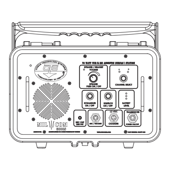
Page 9: Anatomy Of The Surface Station
Anatomy of the Surface Station Automatic Pressure Relief Valve Speaker On/Off Indicator Speaker On/Off & Volume Control Knob Channel Selection Indicators Channel Select Button Squelch On/Off Button Scrambler On/Off Button Battery Level Indicator Transducer/Power On/Off Port Battery Charger Connection Port Mic/Headset Connection Port Line Out Connection Port Speaker... - Page 10 Channel Indicators The Channel Indicators will illuminate to display the channel that has been select- ed by the Channel Select Button. Channel Select Button The Channel Select Button allows you to change the transmit and receive fre- quency of the unit. Squelch On / Off Button The Squelch On / Off Button allows you to switch the squelch functionality either on or off.
- Page 11 Line Out Connection Port The Line Out Connection Port is a female RCA 3.5 mm jack that will allow the user to connect external recording devices or external speakers to the unit. The audio output is Line Level. NOTE: Do not connect phantom power to the jack, doing so can damage the unit.
-
Page 12: Getting Started
Adjustable Handle The Adjustable Handle functions both as the carrying handle for the unit and as the “Kick Stand” for the unit. This allows you to place the unit at any of three use-angles see Section, Getting Started for more information about the use an- gles. - Page 13 Handle In Position 3 (Approximately 180°) To power the unit on, mate up the connector of the transducer cable to the Transducer / Power On / Off Port on the panel, rotate the cable connector gently until it indexes and lock into place with the cable’s locking ring. The unit’s LEDs will illuminate and a voice will read out the current settings.
-
Page 14: Making Adjustments
Making Adjustments The following instructions will explain how and why to change your options and settings of the MilCom Surface Station. The table below lists the factory default options. The unit will remember Channel and Scrambler settings between uses, but will default to Speaker on and Squelch On when powered on. Option Default setting Channel... - Page 15 Speaker To turn the speaker on or off, press down on the volume knob. When the speaker is on the speaker indicator will illuminate. When in the off position, the unit will not have any volume coming from the unit. If the optional headset is connected, audio from the headset can be heard even if the unit speaker is set to off.
- Page 16 Battery Charging The MilCom Surface Station is equipped with a high-capacity rechargeable Lithium-Ion battery that is charged through the Charger connector located along the bottom row of connectors. To charge the unit, connect the provided smart charging device. The LED on the Battery Charger will illuminate red, indicating that charging is in progress.
-
Page 17: Maintenance
Maintenance Routine maintenance of the MilCom Surface Station 6000S units is necessary to ensure an extended life of the equipment. Failure to properly care for and maintain the MilCom Surface Station 6000S and ancillary components could lead to flooding of the units, damage to the connectors, transducers, housings and other failures. -
Page 18: Replacement / Spare Parts
Replacement / Spare Parts Replacement / Spare part Part Number for ordering THB-PMC Headset 900479-000 HHM-5 Hand-Held Microphone 910514-000 RCLi-2 Battery Charger 910510-000 RBLi-8 Battery (2 Required) 900481-002 PMC Volume Knob and Cap 900481-003 PMC Panel Screws and nylon washers 900481-004 PMC Battery Bracket Assembly 900481-005... -
Page 19: Replacement Part Instructions
Replacement Part Instructions NOTICE: For all replacement parts, do not use a power drill or power driver. Doing so will damage the unit. Do not tighten screws over 6 inch-pounds (0.6 newton-meters) Volume Knob 1. Firmly grab hold of the volume knob and pull it away from the panel. It will come loose with some force. - Page 20 2. Remove the panel by lifting it from the panel handles. 3. Using a dull plastic tool, carefully remove the O-Ring located in the O-ring groove under the panel. 4. Replace the O-ring with the new undamaged part. 5. Place the panel back into the case and retighten the ten panel screws and nylon washers.
- Page 21 Battery Bracket & Battery 1. Remove all ten panel screws and Nylon washers and set aside. 2. Lift the panel out of the case assembly and place it face-down on a clear work table. 3. Using a Philips head screw driver, remove the four screws that secure the battery bracket to the panel assembly.
- Page 22 5. Disconnect the battery from the PCB and remove the battery from the battery bracket. 6. Place the battery into the replacement battery bracket. Place the battery brack- et onto the panel assembly, lining the bracket mounting holes with the mounting holes of the PCB.
- Page 23 Transducer cage 1. Remove the four screws and pull the plastic cage a part. Replace the plastic cage and the four screws. Transducers 1. Disassemble the Transducer cage by loosening the four screws. Set the two halves of the cage aside. 2.
- Page 24 3. Replace the Transducer by rotating the locking ring. The transducer will only go on one way. 4.Reassemble transducer cage and tighten the four screws Handle assembly 1. Remove the two visible screws using a Philips head screwdriver 2. Pull the handle open and rotate the handle down two steps as shown 3.
-
Page 25: Troubleshooting Guide
4. Pull the handle apart as you would to rotate it. The handle will now pull free from the unit. 5.Replace handle with new part by reversing these instructions. Troubleshooting Guide Issue Step 1 Step 2 -Connect 12 VDC external battery or No power, when the Trans- 12 VDC power supply ducer is connected... -
Page 26: Understanding Wireless Underwater Communications
UNDERSTANDING WIRELESS UNDERWATER COMMUNICATIONS FACTORS THAT AFFECT WIRELESS COMMUNICATIONS There are many factors that affect the propagation of sound in water. The net result is that communication in water can be affected by local conditions and the kind and depth of dive being conducted. The following sections explain some of the factors that can affect the operating range of underwater communication: DISTANCE The sound intensity from a source varies inversely with the distance from the... - Page 27 WATER TEMPERATURE Variations in water temperature affect sound transmission most. In some areas of the ocean, the temperature changes at a fixed rate over large ranges of depth. If the temperature increases with depth, the velocity of sound increases and the sound waves will be refracted toward the surface.
- Page 28 ZONES OF SILENCE Large natural or man-made objects can block acoustical transmission under cer- tain conditions, in much the same way that a rock blocks a fast-moving current of water. Close to the backside of the rock, in this example, the current is absent and the water seems still.
- Page 29 Notes...
- Page 30 Notes...
- Page 31 Notes...
-
Page 32: Limited Warranty
You must contact an official Ocean Technology Systems (OTS) Service Center or OTS directly to obtain service. If you would like to request an RMA #, please request one electronically by accessing the service section of our website.