Advertisement
Quick Links
Installing and Removing Power Supplies
Connecting to the Power Source
You follow the same steps to install the AC-input and DC-input power supplies, but you must ground them
differently.
• AC-input power supply—It is automatically grounded when you connect its power cable to the power
• DC-input power supply—You do not connect the power supply directly to the earth ground.
You use one power cord for each power supply to connect the power supply to its power source. The number
of power sources you use for your power supplies depends on the mode with which you install them:
• Combined mode (no power redundancy)—Connect both power supplies to the same power source.
• Redundancy mode—Connect each power supply to a separate power source.
Before You Begin
Before you connect power supplies to power sources, ensure the following:
• The chassis is connected to an earth ground. See
• You have receptacles for the power sources within reach of the power supply cables.
• If you are installing more than one DC-input power supply, each must be protected by a dedicated circuit
• The power sources are rated as follows:
• The power supply is already inserted into the chassis.
Ensure that the power source is OFF. As an added precaution, place the appropriate safety flag and lockout
Caution
devices at the source power circuit breaker, or place a piece of adhesive tape over the circuit breaker handle
to prevent accidental power restoration while you are working on the circuit.
Warning
Before performing any of the following procedures, ensure that power is removed from the DC circuit.
Statement 1003
OL-30827-02
supply and the power source.
breaker or a fuse that is sized according to the power supply input rating and the local or national electrical
code requirements.
◦For North American AC-input installations—20 A with 110 V or 220 V circuits.
◦For North American DC-input installations—(–48 VDC nominal at 37 A in North America
(operating range: –40.5 to –56 VDC).
◦For international installations—Size the circuits by local and national standards.
Connecting to the Power Source
Establishing the System Ground, on page
Catalyst 6880-X Switch Hardware Installation Guide
45.
57
Advertisement

Related Manuals for Cisco C6880-X-LE-16P10G


Summary of Contents for Cisco C6880-X-LE-16P10G
- Page 1 Installing and Removing Power Supplies Connecting to the Power Source Connecting to the Power Source You follow the same steps to install the AC-input and DC-input power supplies, but you must ground them differently. • AC-input power supply—It is automatically grounded when you connect its power cable to the power supply and the power source.
- Page 2 Installing and Removing Power Supplies Connecting to the Power Source Connecting to an AC Power Source To connect to a power source, follow these steps: Take care when connecting units to the supply circuit so that wiring is not overloaded. Statement 1018 Warning Procedure Step 1...
- Page 3 The LEDs should flash and then the Output LED should turn on in addition to the Input LEDs. If the FAULT LED is on or flashing, call Cisco TAC for assistance. Removing Power Supplies...
- Page 4 Installing and Removing Power Supplies Removing Power Supplies b) Verify that the OUTPUT LED has turned off. If the LED is still on, return to Step 1. c) If you are removing a DC-input power supply, ensure that the power is turned off at the power source by turning off the power for that circuit, and then verify that the INPUT LEDs turn off.
- Page 5 Finding the Serial Number If you contact Cisco Technical Assistance, you need to know the serial number. These figures show where the serial number is located. You can also use the show version privileged EXEC command to see the serial number.
- Page 6 Installing and Removing Power Supplies Finding the Serial Number Catalyst 6880-X Switch Hardware Installation Guide OL-30827-02...
-
Page 7: Table Of Contents
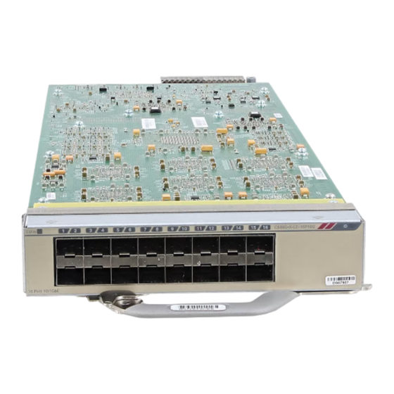
The chassis should only be operated with either a modular port card installed or a blank module installed in the half-modular slots. Port Card Model Description C6880-X-LE-16P10G Multirate port card with standard tables. This module has 16 10-Gigabit, 1-Gigabit, or 100BASE-FX fiber-optic slots, which support 1-Gigabit SFPs, 10-Gigabit SFP+, or 100BASE-FX fiber-optic modules. - Page 8 Installing the Modular Port Card Modular Port Card LEDs Figure 26: Modular Port Card (C6880-X-LE-16P10G and C6880-X-16P10G) 16 SFP+ or 100BASE-FX SFP ports Extraction handle Status LED Port card Port LEDs ID (blue beacon LED) For a list of supported SFP and SFP+ modules, see the switch data sheet:http://www.cisco.com/c/en/us/...
-
Page 9: Modular Port Card Installation
Installing the Modular Port Card Modular Port Card Installation Modular Port Card Installation Use only supported modular port cards and SFP or SFP+ modules. Note The switch can operate without a port card, but a blank port card module (with no ports or SFP slots) is available and must be installed when the port card module is not installed. - Page 10 Installing the Modular Port Card Installing a Modular Port Card Step 3 Remove the modular port card from the protective packing. Step 4 Press the lever on the extraction handle to release the latch, and rotate the handle outwards. Figure 28: Pressing the Lever on the Port Card Step 5 Insert the port card into the chassis.
-
Page 11: Installing Sfp And Sfp+ Transceiver Modules In The Port Card
Installing the Modular Port Card Installing SFP and SFP+ Transceiver Modules in the Port Card Installing SFP and SFP+ Transceiver Modules in the Port Card Before You Begin You must have the port card installed to use SFP and SFP+ transceiver modules. Class 1 laser product. -
Page 12: Removing Sfp Or Sfp+ Modules From The Modular Port Card
Installing the Modular Port Card Removing SFP or SFP+ Modules from the Modular Port Card Step 6 Remove the SFP or SFP+ dust plugs and save for future use. Step 7 Connect the SFP cables. Figure 31: Connecting the SFP Cable Removing SFP or SFP+ Modules from the Modular Port Card Procedure Step 1... - Page 13 Installing the Modular Port Card Removing SFP or SFP+ Modules from the Modular Port Card Step 3 Use the bale-release latch side of the tool to lift the bale up, and remove the SFP or SFP+ module. Figure 33: Removing the SFP Module from the Port Card Step 4 Grasp the SFP or SFP+ transceiver module, and carefully remove it from the slot.
-
Page 14: Removing A Modular Port Card
Installing the Modular Port Card Removing a Modular Port Card Removing a Modular Port Card Procedure Step 1 Attach an ESD-preventive wrist strap to your wrist and to an earth ground surface. Figure 34: Attaching an ESD Strap Catalyst 6880-X Switch Hardware Installation Guide OL-30827-02... - Page 15 Installing the Modular Port Card Removing a Modular Port Card Step 2 Always remove any cables before removing the port card from the slot. Disconnect the cables from the SFP+ transceiver modules. Step 3 (Optional) Remove the SFP+ transceiver modules from the port card. Step 4 Press on the extraction handle to release the latch and rotate the handle outwards to extract the card.
-
Page 16: Finding The Modular Port Card Serial Number
Finding the Modular Port Card Serial Number If you contact Cisco Technical Assistance, you need to know the port card serial number. This figure shows where the serial number is located. You can also use the show version privileged EXEC command to see the serial number. - Page 17 C H A P T E R Replacing the Fan Tray • Required Tools, page 73 • Removing the Fan Tray, page 73 • Installing the Fan Tray, page 75 • Checking the Installation, page 76 • Finding the Fan Serial Number, page 77 Required Tools You might need a flat-blade or number 2 Phillips-head screwdriver to loosen or tighten the captive installation screws on the fan tray.
- Page 18 Replacing the Fan Tray Removing the Fan Tray Make sure there is adequate slack in the network interface cables to allow the cable guide to pivot Note down far enough to access the fan tray. If there is insufficient slack in the cables, the cable guide will not pivot far enough to give you access to the fan trays.
- Page 19 Replacing the Fan Tray Installing the Fan Tray Step 4 Pull the fan tray clear of the chassis, and set it aside. Figure 39: Removing the Fan Tray Installing the Fan Tray Procedure Step 1 Hold the fan tray with the captive screw at the bottom. Step 2 Place the fan tray into the front chassis cavity so that it rests on the chassis, and then lift the fan tray up slightly, aligning the top and bottom chassis guides.
- Page 20 Verify that the FAN STATUS LED is green. If the LED is red, one or more of the fans are faulty. If after several attempts the fans do not operate or if you experience trouble with the installation (for instance, if the captive installation screws do not align with the chassis holes), contact a Cisco customer service representative for assistance.
- Page 21 Finding the Fan Serial Number If you contact Cisco Technical Assistance, you need to know the fan serial number. This figure shows where the serial number is located. You can also use the show version privileged EXEC command to see the serial number.
- Page 22 Replacing the Fan Tray Finding the Fan Serial Number Catalyst 6880-X Switch Hardware Installation Guide OL-30827-02...
- Page 23 A P P E N D I X Technical Specifications • Switch Specifications, page 79 • Power Supply Module Specifications, page 81 • 3000 W Power Supply AC Power Cords, page 82 • Fan Module Specifications, page 90 • Chassis and Module Power and Heat Values , page 90 Switch Specifications Environmental Specification...
- Page 24 Technical Specifications Switch Specifications Environmental Specification Altitude, operating Certified for operation: 0 to 6500 ft (0 to 2000 m) Designed and tested for operation: –200 to 10,000 ft ( –60 to 3000 m) Shock and vibration Shock • Operational — 5 G 30 ms, half-sine (IEC 68-2-27) •...
- Page 25 Technical Specifications Power Supply Module Specifications Environmental Specification Airflow C6880-X-FAN Note The airflow in the Catalyst 6880-X switch chassis is from right to left. See Site Requirements, on page 17 for recommended separations between walls and the chassis air intake and air exhaust and between the air exhaust of one chassis with the air intake of another chassis.
- Page 26 Technical Specifications 3000 W Power Supply AC Power Cords C6880-X-3KW-AC C6880-X-3KW-DC British thermal units (BTUs) • 11,440 BTU/hour at 3051W • 11,567 BTU/hour at 3051 W output output • 5563 BTU/hour at 3051W • 5880 BTU/hour at 1551 W output output Output holdup time 20 milliseconds (ms) minimum...
- Page 27 Technical Specifications 3000 W Power Supply AC Power Cords Locale AC Source Plug Cordset Power Cord Part Number and Reference Type Rating Illustration Brazil EN60320 / C19 16 A, 250 Figure 43: UCSB-CABL-C19-BRZ= (Brazil), on page 85 People's Republic of GB16C 16 A, 250 Figure 44: CAB-AC16A-CH= (People's...
- Page 28 Technical Specifications 3000 W Power Supply AC Power Cords 4 The PDU power cable is designed for users who power their switch from a PDU. The end of the cable that plugs into the chassis power supply has a C19 connector;...
- Page 29 Technical Specifications 3000 W Power Supply AC Power Cords AC Power Cord Illustrations Figure 41: CAB-IR2073-C19-AR= (Argentina) Figure 42: CAB-AC-16A-AUS= (Australia, New Zealand) Figure 43: UCSB-CABL-C19-BRZ= (Brazil) Figure 44: CAB-AC16A-CH= (People's Republic of China) Catalyst 6880-X Switch Hardware Installation Guide OL-30827-02...
- Page 30 Technical Specifications 3000 W Power Supply AC Power Cords Figure 45: CAB-AC-2500W-EU= (Continental Europe) Figure 46: CAB-SABS-C19-IND= (India) Figure 47: CAB-AC-2500W-INT= (International) Catalyst 6880-X Switch Hardware Installation Guide OL-30827-02...
- Page 31 Technical Specifications 3000 W Power Supply AC Power Cords Figure 48: CAB-AC-2500W-ISRL= (Israel) Figure 49: CAB-7513ACI= (Italy) Figure 50: CAB-AC-2500W-US1= (Japan, North America [Nonlocking Plug] 200 to 240 VAC operation) Catalyst 6880-X Switch Hardware Installation Guide OL-30827-02...
- Page 32 Technical Specifications 3000 W Power Supply AC Power Cords Figure 51: CAB-AC-C6K-TWLK= (Japan, North America [Locking Plug] 200 to 240 VAC operation) Catalyst 6880-X Switch Hardware Installation Guide OL-30827-02...