Table of Contents
Advertisement
Quick Links
Advertisement
Table of Contents

Related Manuals for JVC RM-LP5G

Summary of Contents for JVC RM-LP5G
- Page 1 JVC Compact Joystick PTZ Controller RM-LP5G User Manual V1.0...
-
Page 2: Table Of Contents
Content Parameters & Specs Communication & Control Interface Camera Control and Operation Control Signal Format Power Supply and Consumption Physical & Others Description of Controls Interface and Connection Diagram Upgrade Interface RS422/RS485 Interface RS232 Interface LAN Interface DC Power Supply Interface System Menu Operation Instructions System Menu Function System Menu... -
Page 3: Parameters & Specs
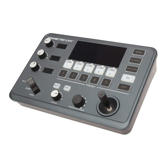
Parameters & Specs Communication & Control Interface RS422/RS485 Interface Phoenix Contact 4 pin 3.81mm Terminal RS232C Interface DB9 Male Interface LAN Interface RJ45 Female Interface Power Supply JEITA type4 Female Interface Upgrade Online Micro USB Female Interface Camera Control or Operation Camera Support Communication Protocol VISCA, PELCO P/D, UDP... - Page 4 Description of Button & Knob Function ④ ⑤ ⑪ ⑮ ① ⑭ ② ③ ⑦ ⑥ ⑫ ⑬ ⑨ ⑩ ① Rotation Knob to adjust the Camera Exposure Parameter or Red Gain Value, Turn Right to valued Increase, Turn Left to Decrease. ②...
- Page 5 Description of Button & Knob Functions [OPT key] is used to trigger single focus of the camera. At the same time, the camera enters the one-shot auto focus mode. ⑨ PTZ Speed Adjustment Knob This knob is used to adjust the speed of Camera Pan, Tilt and Zoom. The Current Speed will be displayed on the Led Display.
- Page 6 and then press the preset number to be cleared. >When the menu selection is in 10 presets Mode. the [RESET] Button is changed to a presets expansion compound key, which is used to set and call 6-10 preset positions. [RESET]+]CAM1-5]TO Setting or Call 6-10 Presets. Set Presets 6-10 Press the [RESET] key, at the same time of the number keys [1-5] and [CAM1-CAM5] will light up in green at the same time, and the camera channel keys [CAM1-CAM5] will be...
- Page 7 Exposure Mode Knob 1 Knob 2 Knob 3 Auto NOT USED NOT USED Exposure Compensation Manual Shutter Iris Gain Shutter Priority Shutter NOT USED Exposure Compensation Iris Priority Iris NOT USED Exposure Compensation Brightness Priority Iris Gain Exposure Compensation Table 1 [ WB MODE Key ] ●...
- Page 8 Description of Button & Knob Function Execution Command Auto 8x 01 04 35 00 FF Normal Auto Indoor 8x 01 04 35 01 FF Indoor mode Outdoor 8x 01 04 35 02 FF Out door mode CAM_WB One Push WB 8x 01 04 35 03 FF One Push WB mode 8x 01 04 35 04 FF...
- Page 9 Description of Button & Knob Function Inquiry Command y0 50 00 FF Auto y0 50 01 FF In Door y0 50 02 FF Out Door CAM_WBModeInq 8x 09 04 35 FF y0 50 03 FF One Push WB y0 50 04 FF y0 50 05 FF Manual CAM_RGainInq...
- Page 10 Interface Function and Connection Diagram ① ② ③ ④ ⑤ ① Upgrade Interface This interface is to upgrade keyboard firmware by laptop. Using Micro USB Cable direct connection with a PC and upgrade tools software. ② RS422/RS485 Interface This Interface is used to connect with Cameras by RS422 or RS485, detailed connection diagram as follows:...
- Page 11 Interface Function and Connection Diagram ③ RS232 Interface This Interface is using to connect with Cameras through RS232, detailed connection diagram as follows : ④ LAN Interface The LAN Interface is for connection with a Network switch. Network PTZ Camera, detailed connection diagram as follows: Connect with Single Unit Network PTZ Camera:...
- Page 12 Interface Function and Connection Diagram Connect with multiple cameras by LAN interface detailed connection diagram as ● follows: (When connecting multiple cameras, you need to set the IP of each camera separately with a computer). S w i t c h i ( 1 0 B A S E - T / 1 0 0 B A S E - T X , c o m m e r c i a l l y a v a i l a b l e ) P C f o r s e t t i n g...
-
Page 13: System Menu Operation Instructions
System Menu Operation Instructions System Menu Operation & Explanation 1.Long Press [ MENU ] for 3 seconds to turn on the Keyboard system Menu; 2.The joystick swings up and down: control the system menu cursor to move up and down / change the parameters of the current menu item; 3.The Joystick swings Right: enter the current menu item / save and exit the current menu item;... - Page 14 Due to the differences in the AE/WB parameter values corresponding to different brands of cameras, the actual function of the knob may vary. Before using, please set the camera brand of the corresponding channel, you can choose: JVC, PUAS, SONY, VHD, Minrray, Bolin... ETHERNET SETTING 1. Channel:...
- Page 15 System Menu Operation Instructions PASSWORD SETTING 1. Using Password: Enabled Move the cursor to [ Password Setting ], 2. Modify Password then move right to enter Password : [ Using Password ] ● When the password function is Enabled, a password is required to enter the menu.
-
Page 16: System Menu
2. Address: 1~7(VISCA); 1~255(PELCO-D/P) SYSTEM COMM 3. Baud Rate: 2400, 4800, 9600, 19200, 38400bps MENU SETTING 4. Protocol: VISCA、PELCO P/D、UDP 5. Camera Brand: JVC,PUAS, SONY, VHD, Minrray, Bolin 1. Channel: CAM1~CAM5 ETHERNET 2. Cam IP : 192.168. 000.010~14 SETTING Port: 52381 1. -
Page 17: Products Dimensions
Products Dimensions (Units of measure: mm) - 16 -...