
Related Manuals for Canon imagePASS-R1

Summary of Contents for Canon imagePASS-R1
- Page 1 SERVICE MANUAL Canon December 2, 2020 Rev. 1 COPYRIGHT 2020 CANON INC. CANON imagePASS-R1 Rev. 1 PRINTED IN U.S.A. ©...
- Page 2 When changes occur in applicable products or in the contents of this manual, Canon will release technical information as the need arises. In the event of major changes in the contents of this manual over a long or short period, Canon will issue a new edition of this manual.
- Page 3 Important Notices Copyright The copyright of this document belongs to Canon Inc. This document may not be copied, reproduced or translated into another language, in whole or in part, without the prior consent of Canon Inc. Copyright CANON INC. 2020 Caution Use of this manual should be strictly supervised to avoid disclosure of confidential information.
- Page 4 Important Notices Symbols Explanation Symbols Explanation Cleaning is needed. Measurement is needed. The following rules apply throughout this Service Manual: 1. Each chapter contains sections explaining the purpose of specific functions and the relationship between electrical and mechanical systems with reference to the timing of operation. In the diagrams, represents the path of mechanical drive;...
-
Page 5: Table Of Contents
Contents Contents 1. Introduction...................... 1 Introduction............................2 About the imagePASS..........................2 About this document..........................2 How the imagePASS operates........................ 3 Before you service the imagePASS......................3 Tools you will need..........................3 Precautions............................4 Specifications............................7 Hardware features..........................7 Physical specifications...........................7 Safety and emissions compliance......................8 System Software...........................8 User Software............................8 Checking the Service Mode of Connection Engine.................. -
Page 6: Introduction
Introduction Introduction........... 2 Specifications........7... -
Page 7: Introduction
1. Introduction Introduction This document includes information about servicing the imagePASS-R1. In this document, imagePASS-R1 is referred to as the “imagePASS.” About the imagePASS The imagePASS embeds computer connectivity and highly efficient PostScript and PCL printing capacity into the imageRUNNER DX C5870/C5860/C5850/C5840 Series. -
Page 8: How The Imagepass Operates
1. Introduction Server software: The imagePASS software. Runs on Linux operating system. Document conventions NOTE: The NOTE format highlights important messages and additional information. WARNING: The WARNING icon indicates a warning concerning operations which, if not performed correctly, may lead to death or injury. -
Page 9: Precautions
1. Introduction Precautions This section includes information about how to safely operate and service the imagePASS and how to avoid damage to imagePASS components. Report shipping damage If there is evidence of shipping damage, save the shipping boxes and damaged parts. Call the shipper immediately to file a claim and notify your authorized service/support center. - Page 10 1. Introduction Avoid fan blades WARNING: The imagePASS contains hazardous moving parts. When servicing the imagePASS, keep away from moving fan blades. Attention: ce produit contient des pièces mobiles dangereuses. Veuillez le maintenir à l'écart des pales de ventilateur lors de sa maintenance.
- Page 11 1. Introduction Do not have liquids near the imagePASS If liquid spills on the imagePASS, immediately unplug the imagePASS. Do not open the power supply For more information about the power supply, see “Power supply” on page Do not open the hard disk drive For more information about the hard disk drive, see “Hard disk drive (HDD)”...
-
Page 12: Specifications
1. Introduction Specifications The imagePASS has, or makes use of, the following features. Hardware features Item Content Print Resolution 1200 dpi x 1200 dpi, 600 dpi x 600 dpi Page Description Language(s) Adobe PS3 Memory 4GB (1x4GB) *8GB (2x4GB) with Fiery with "Adobe PDF Print Engine KIT" Hard Disk Drive 500 GB SATA Processor Speed... -
Page 13: Safety And Emissions Compliance
When connecting imagePASS, it is necessary to select the engine service mode COPIER > OPTION > INT-FACE > IMG-CONT to ”3”. When the controller is connected, the automatically recognized value is displayed in the following service mode. COPIER > OPTION > INT-FACE > CNT-TYPE > xxx CNT-TYPE Model imagePASS-R1... -
Page 14: How To Obtain The Fiery Password
1. Introduction How to obtain the Fiery password To log on to the imagePASS as an administrator or operator, you must obtain the Fiery password. To obtain the Fiery password 1. Make sure that the imagePASS is connected to the printer. 2. -
Page 15: Using The Imagepass
Using the imagePASS Using the imagePASS......11... -
Page 16: Using The Imagepass
2. Using the imagePASS Using the imagePASS This chapter describes how to use the imagePASS. Starting, shutting down, rebooting, and restarting the imagePASS Always use the following procedures to start, shut down, reboot, or restart the imagePASS. IMPORTANT: Always verify that the imagePASS is not in use before you power off or restart it. Make sure that the system is not processing or printing a job. - Page 17 2. Using the imagePASS 3. From the printer touch panel, select Fiery > Tools > Restart Server >Reboot Server. Figure 3a: The imagePASS Tools menu ■ To restart the imagePASS 1. Make sure that the imagePASS is not receiving, processing, or printing jobs. 2.
- Page 18 2. Using the imagePASS 3. From the printer touch panel, select Fiery > Tools > Restart Server. Figure 3b: The imagePASS Tools menu...
-
Page 19: Replacing Parts
REPLACING PARTS Replacing Parts........15... -
Page 20: Replacing Parts
3. REPLACING PARTS Replacing Parts Generally, the imagePASS does not require regular maintenance. Use the procedures in this chapter to inspect, remove, reseat, or replace major hardware components. Overview This chapter includes information about the following: • Diagrams of imagePASS components (“imagePASS components”... - Page 21 3. REPLACING PARTS Figure 4: Exploded view of imagePASS components Parts Name Chassis cover Printer interface board CPU cooling assembly 4GB DIMM 3.3GHz CPU Security chip Battery Motherboard 500GB SATA HDD(hard disk drive) HDD bracket Chassis fan Chassis fan guard Service board HDD SATA data cable 10-pin power button cable...
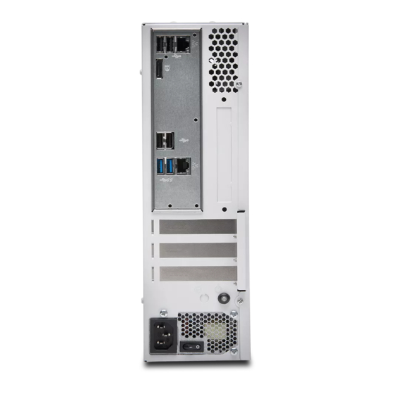
- Page 22 3. REPLACING PARTS Parts Name Power supply Power switch Chassis Power supply duct ■ imagePASS connector panel and LED diagnostic codest The connector panel of the imagePASS has the external connectors and power switch. Familiarize yourself with the connector panel of the imagePASS. Figure 5: imagePASS connector panel Name Type A USB2.0 ports (x2)
-
Page 23: Accessing The Imagepass
3. REPLACING PARTS Figure 6: LED display Name Service switch LED display If the LED display hangs on a code other than 00, one or more diagnostic tests may have failed. Look up the diagnostic code in “If the printer does not print” on page 76 to determine the troubleshooting actions that you should take. -
Page 24: Checking Imagepass Internal Connections
3. REPLACING PARTS 7. Raise the cover and slide it toward the connector panel of the chassis to remove it. Set aside the cover so that you can replace it later. The imagePASS internal components are now accessible. Figure 7: Removing the chassis cover Checking imagePASS internal connections The most common causes of problems are faulty and loose connections. -
Page 25: Removing And Replacing Imagepass Components
3. REPLACING PARTS 8. Check the 10-pin power button cable that connects the printer interface board (J351) and the motherboard (J11). Make sure that the cable is intact. The following diagrams illustrate the internal cable connections between hardware components and the motherboard. Figure 8: imagePASS internal cable connections Name Power supply... - Page 26 3. REPLACING PARTS • CPU and CPU cooling assembly • Service board • Chassis fan • Power supply • Hard disk drive (HDD) For information about replacing other components, see the documentation that accompanies your printer. IMPORTANT: Be sure to use an ESD grounding wrist strap and follow standard ESD (electrostatic discharge) precautions while performing these procedures.
- Page 27 3. REPLACING PARTS 3. Remove the mounting screw that secures the printer interface board to the imagePASS chassis (see figure below). Set aside the mounting screw so that you can replace it later. Figure 10: Removing the printer interface board Name Mounting screw 4.
- Page 28 3. REPLACING PARTS 2. To release a DIMM, push outward on the levers on each side of the DIMM (see below figure). Figure 11: Releasing a DIMM Name Lever DIMM Slot notch 3. Lift the DIMM straight out of the slot. 4.
- Page 29 3. REPLACING PARTS CAUTION: There is a danger of explosion if the battery is replaced with the incorrect type. Replace it only with the same type recommended by the manufacturer. Dispose of used batteries according to the manufacturer’s instructions. ACHTUNG: Es besteht Explosionsgefahr, wenn die Batterie durch eine Batterie falschen Typs ersetzt wird.
- Page 30 3. REPLACING PARTS 3. Carefully push the clip away from the battery until the socket ejects the battery. Figure 12: Motherboard battery Name Clip Battery Socket 4. Slide the battery out of its socket. 5. Wait two minutes to allow the motherboard electrical components to fully discharge. 6.
- Page 31 3. REPLACING PARTS Figure 13: Diagram of the motherboard Name HDD data connector (SATA0) Security chip (J23) Battery (CR1) Printer interface board (PCIEx16) Power button pins (J11) DIMM-A0 DIMM-B0 Crossover Ethernet port / Type A USB3.0 ports (x2) Type A USB2.0 connector (x2) Type A USB2.0 ports (x2) / Network port (RJ-45) CPU and cooling assembly MS Mounting screws 24-pin power connector (J24)
- Page 32 3. REPLACING PARTS • All boards installed on the motherboard • All cables connected from other components to the motherboard (these include both motherboard power cables, chassis fan cable, HDD data cable, 10-pin power button cables, and service board cable) IMPORTANT: Follow standard ESD precautions while handling the motherboard and all components.
- Page 33 3. REPLACING PARTS 2. Lift the motherboard edge opposite to the connector panel to release the motherboard from the chassis, and then gently slide the motherboard out of the chassis. NOTE: Make sure to lift the motherboard edge near the DIMM area, so that the underside of this area clears the nearby screw standoff. Make sure that the connectors on the motherboard clear the cutouts in the chassis as you remove the board.
- Page 34 3. REPLACING PARTS 2. Remove the security chip from socket J23 on the old motherboard (see “Motherboard jumpers” on page 25). Carefully position the extraction tool around the edges of the security chip, and pull the chip straight out of the socket. Make sure not to put stress on surrounding components.
- Page 35 3. REPLACING PARTS 4. Install the security chip in socket J23 on the new motherboard. NOTE: Be sure to align the small notch in the security chip with the notch in the outline that appears inside socket J23. If you install the security chip incorrectly, you may corrupt the security chip and/or the motherboard. Figure 16: Aligning the security chip Name Security chip...
- Page 36 3. REPLACING PARTS 2. Angle the motherboard so that the connectors on the motherboard fit into the cutouts in the connector panel of the chassis, and gently slide the motherboard into the chassis (see “To remove the motherboard” on page 27).
- Page 37 3. REPLACING PARTS Unlocking the HDD, go to WebTools and enter Fiery password. (see “Unlocking the HDD” on page 1. Make sure that the imagePASS is powered on. 2. From a client computer, start a web browser and enter the IP address of the imagePASS. 3.
- Page 38 3. REPLACING PARTS Figure 18: CPU cooling assembly Name CPU fan Heatsink Load plate CPU socket on motherboard Socket lever ● To remove a CPU 1. Access and open the imagePASS, as described on “Accessing the imagePASS” on page 2. Remove the motherboard components (see “To remove motherboard components from the motherboard”...
- Page 39 3. REPLACING PARTS 5. Remove the CPU cooling assembly: CAUTION: Be aware that both the cooling assembly and the CPU may be very hot. You may need to allow the components to cool before you attempt to remove them. • Loosen the four screws that secure the cooling assembly to the motherboard. Partially loosen all the screws before loosening any one screw all the way.
- Page 40 3. REPLACING PARTS 7. Open the load plate (see below figure). Figure 20: Removing/replacing the CPU Name Yellow triangle Load plate open Flat corner of socket border Socket lever in the open position 8. Grasp the CPU by its edges, lift it out of the socket, and then place the CPU in a safe place. NOTE: If you remove the CPU from the motherboard to install it on a new motherboard, unpack the new motherboard and remove the protective plastic cover from the CPU socket.
- Page 41 3. REPLACING PARTS 2. Prepare the CPU socket by ensuring that: • The socket lever is in the open position. • The load plate is open. 3. Place the CPU in the socket (see “To remove a CPU” on page 33).
- Page 42 3. REPLACING PARTS 4. Remove the two screws that secure the service board to the chassis, and remove the board from the chassis (see below figure). Figure 21: Removing/replacing the service board Name Service board Screw (1 of 2) ● To replace the service board 1.
- Page 43 3. REPLACING PARTS 3. Remove the four plastic rivets that attach the fan to the chassis, and remove the fan. To remove a rivet, use a flathead screwdriver to pry loose the rivet head on the outside of the chassis while squeezing and pushing the locked end of the rivet with your fingers or a pair of pliers.
- Page 44 3. REPLACING PARTS ● To replace the chassis fan 1. If you are installing a new chassis fan, attach the fan guard to the correct face of the new fan. Use the fan guard and four rivets that you removed from the old chassis fan. Position the guard against the face of the new fan so that the airflow arrow on the fan points toward the guard (see “To remove the chassis fan”...
- Page 45 3. REPLACING PARTS IMPORTANT: Do not open the power supply for service or troubleshooting purposes. Opening the power supply voids the warranty. ● To remove the power supply and power switch 1. Access and open the imagePASS, as described on “Accessing the imagePASS”...
- Page 46 3. REPLACING PARTS 4. Connect the HDD power cable to the SATA power connector on the HDD. 5. Connect the 4-pin (2x2) power cable to the 4-pin connector on the motherboard. For the location of the motherboard connector, see “Motherboard jumpers” on page Connect the power cable to pins 1 through 4 of the motherboard connector.
- Page 47 3. REPLACING PARTS 6. Carefully lift the HDD assembly to release its lower edge from the mounting posts in the chassis, and then remove the HDD assembly from the chassis. Figure 27: Removing the HDD assembly Name Screw (1 of 2) HDD assembly...
- Page 48 3. REPLACING PARTS 7. If you are replacing the HDD with a new HDD, remove the HDD from its bracket. Remove the four screws that secure the HDD to the HDD bracket (see below figure). Remove the HDD bracket and set it aside so that you can replace it later.
-
Page 49: Restoring Imagepass Functionality After Service
3. REPLACING PARTS 10. If you replaced the HDD with a new HDD, install system software (see “Installing System Software” on page 47). 11. Verify the functionality of the imagePASS (see “To reinstall and verify the imagePASS” on page 44). Restoring imagePASS functionality after service Complete your inspection and service by reinstalling and verifying the imagePASS. - Page 50 3. REPLACING PARTS 6. If you installed a new HDD, install system software (see “Installing System Software” on page 47). A spare HDD is shipped without preinstalled system software. 7. Make sure to configure the date and time in Setup (see “To configure the system date and time”...
-
Page 51: Installing System Software
INSTALLING SYSTEM SOFTWARE Installing System Software....47... -
Page 52: Installing System Software
4. INSTALLING SYSTEM SOFTWARE Installing System Software The imagePASS system software is installed on the HDD at the factory. You must install system software if a more recent version is required, you replace the HDD, or you discover problems with the current system. System software installation reminders Keep in mind the following when installing system software: Compatibility:... - Page 53 4. INSTALLING SYSTEM SOFTWARE • Color Settings • Scan Settings • FreeForm/VDP Resources • Virtual Printers • Server Presets • Fonts • Job Log NOTE: If you cannot create a configuration file as described in the following procedure, ask the site administrator to archive custom files (such as color profiles and customer-installed fonts) to removable media or a network location.
-
Page 54: Using Fiery System Restore
4. INSTALLING SYSTEM SOFTWARE 5. Log on with Administrator privileges and click OK. On the Fiery Server Configuration page, look for ID in the BIOS Setup section. The alphanumeric characters in the ID field is the default password.(Print the Configuration page: Press the Fiery logo, then press [Info] >... - Page 55 4. INSTALLING SYSTEM SOFTWARE NOTE: imagePASS supports only USB flash drives, it does not support external USB HDD. It is recommended to use USB flash drives with enough capacity. You must login to the system as a system administrator to use the Fiery System Restore features. NOTE: Guide the site administrator with the procedures on how to backup and what data must be backed-up before re-installaing the system software.
- Page 56 4. INSTALLING SYSTEM SOFTWARE 2. Select Enable automatic backup, and select when you want to start the backup process on the imagePASS. NOTE: The backup process takes more than an hour to complete and it requires the imagePASS to be in Idle status. If the imagePASS is not in Idle status, the backup process does not start.
-
Page 57: Installing The System Software
4. INSTALLING SYSTEM SOFTWARE 4. Click Continue. ■ To restore the system by booting from a bootable USB flash drive You can restore from a bootable USB flash drive by following the installation procedure described in “To install the system software”... - Page 58 4. INSTALLING SYSTEM SOFTWARE ■ Fiery Installer Builder You can download the Fiery Installer Builder from EFI Sales Portal. Using the Fiery Installer Builder you can perform the following tasks: • Download the system software files from EFI cloud server to your local or network storage location. •...
- Page 59 4. INSTALLING SYSTEM SOFTWARE 4. Navigate to the downloaded Fiery Installer Builder .exe file and then double-click to install. When the installation is complete, the Fiery Installer Builder window appears automatically. The installation creates the Fiery Installer Builder icon on the Windows desktop. ■...
- Page 60 4. INSTALLING SYSTEM SOFTWARE imagePASS-R1 V1.0 If the Add button is displayed at the center of the window, no product is copied to this device yet. 4. Click Add. 5. At the Login the EFI Portal window, enter your EFI Sales Portal account credentials, and click Login. Proceed to step 6.
- Page 61 Default User name and Password User name: Admin Password : Fiery password (See “How to obtain the Fiery password” on page Contact the site administrator for the administrator’s account information. 6. At the Select a Brand window, select Canon and click Next.
- Page 62 4. INSTALLING SYSTEM SOFTWARE 7. At the Select a Product window, select imagePASS-R1 V1.0 and click Next. Canon imagePASS-R1 V1.0 8. At the Select a Build window, select the latest build and click Next. 9. At the Summary window, click Terms of Use and Privacy Policy links to read the software license terms and conditions.
- Page 63 16GB. 2. Start the Fiery Installer Builder. Double-click the Fiery Installer Builder icon on the desktop or you can also click Start > EFI > Fiery Installer Builder. 3. At the Downloaded window, select imagePASS-R1 V1.0. imagePASS-R1 V1.0...
- Page 64 4. INSTALLING SYSTEM SOFTWARE 4. From the Prepare action pull-down menu, select Prepare USB Flash drive and click Next. Canon imagePASS-R1 V1.0 Click NEXT.
- Page 65 4. INSTALLING SYSTEM SOFTWARE 5. At the Select Flash drive window, click the USB flash drive that you attached to the computer, and click Next. If more than one USB devices are displayed, make sure to select the USB flash drive that you attached for loading the system software.
- Page 66 4. INSTALLING SYSTEM SOFTWARE 2. If possible, print the Configuration pages (see “Printing the Configuration pages” on page 67). The Configuration pages contain a list of any installed options and a record of the customer’s current Setup configuration. 3. If you are reinstalling the same version of system software, back up the current system configuration (see “Backing up the system configuration”...
- Page 67 4. INSTALLING SYSTEM SOFTWARE 11. Check the LED display for the file transfer activity. After confirming the LED activity starts and the LED display shows the cyclic codes (C1 > C2 > C3 > C1...), turn off the printer using the main power switch on the front. 12.
- Page 68 It is important that you complete all of the tasks in the preceding list. If you do not complete these tasks, the installation may fail. 4. At the Downloaded window of the Fiery Installer Builder, select imagePASS-R1 V1.0. imagePASS-R1 V1.0...
- Page 69 4. INSTALLING SYSTEM SOFTWARE Canon imagePASS-R1 V1.0 6. Read the instructions in the windows, and click Next. 7. Switch off the Host Machine and confirm that the imagePASS is cut off. (see “Starting, shutting down, rebooting, and restarting the imagePASS” on page 11 8.
- Page 70 4. INSTALLING SYSTEM SOFTWARE 10. Connect the Ethernet cable between the imagePASS network port and an Ethernet port on the Windows computer. NOTE: • Ethernet port: Connected to the imagePASS upper part (for the user network). • Ethernet cable: Use crossover cable 11.
- Page 71 4. INSTALLING SYSTEM SOFTWARE A message appears that indicates that the installation has started. NOTE: After confirming the LED activity starts and the LED display shows the cyclic codes (C1 > C2 > C3 > C1...), turn off the printer using the main power switch on the front.
-
Page 72: Printing The Configuration Pages
4. INSTALLING SYSTEM SOFTWARE 16. Make sure that the imagePASS power switch is in the ON (|) position, and power on the imagePASS (see “To start the imagePASS” on page 11). 17. Power on the printer using the main power switch. Allow the imagePASS to start up and reach Idle (00 should appear on the imagePASS LED display). -
Page 73: Troubleshooting
TROUBLESHOOTI Troubleshooting........69... -
Page 74: Troubleshooting
5. TROUBLESHOOTING Troubleshooting This chapter identifies the source of common problems that may occur with the imagePASS and suggests ways of correcting them. Troubleshooting process The following sections identify the sources of common problems that may occur with the imagePASS and suggest ways of correcting them. - Page 75 5. TROUBLESHOOTING For more information, see the following topics: • “imagePASS connector panel and LED diagnostic codest” on page 17 • “Checking imagePASS internal connections” on page 19 For more information about servicing and troubleshooting problems with the printer, see the documentation that accompanies the printer.
- Page 76 5. TROUBLESHOOTING Symptom Possible cause Suggested action FF (during the start- Possibly one of the following: 1. Replace the motherboard. up, imagePASS • Faulty motherboard 2. Replace the CPU. • Faulty or missing CPU hangs displaying FF) NOTE: FF shown after the imagePASS becomes Idle or shortly at the startup does not indicate an error status.
- Page 77 5. TROUBLESHOOTING Symptom Possible cause Suggested action User authentication Faulty printer interface connections Check connections of the printer interface board and replace as- feature of the printer sociated cables or the printer interface board, if necessary. does not work System problems Clock is slow;...
- Page 78 5. TROUBLESHOOTING Symptom Possible cause Suggested action The LED on the im- Failed to format the hard disk drive. Replace the hard disk drive. agePASS shows error codes EE - > 43.-> EE -> 43..The LED on the im- The USB device may have a corrupted im- 1.
- Page 79 5. TROUBLESHOOTING Symptom Possible cause Suggested action Scanning Problems with scan- • Loose, incorrect, or missing connection 1. Check and reseat the printer interface cable between the im- ning or sending files between the imagePASS and printer agePASS and the printer. •...
- Page 80 5. TROUBLESHOOTING Symptom Possible cause Suggested action Color quality is not Out of calibration or calibration information/ 1. If you suspect that a custom calibration setting is causing the consistent curves on the active partition are corrupted problem, reset the calibration setting to its default measure- ments: In Command WorkStation >...
- Page 81 5. TROUBLESHOOTING Symptom Possible cause Suggested action If the user can print the Configuration page from the printer touch panel but cannot print a job from a computer on the network, request that the site administrator do the following: • Check all printer components of the network, including cables, connectors, terminators, network adapter boards, and network drivers.
-
Page 82: Cleaning The Imagepass
5. TROUBLESHOOTING Possible Cause Solution Can you print a Test Page from the printer • If you cannot print the Test Page, the printer may be out of order. driver? • You may need to service the printer. Is the enclosed fan present andfunctioning? •... -
Page 83: Troubleshooting Information
5. TROUBLESHOOTING • To maintain the air flow inside the chassis and prevent the temperature rising, make sure to clean the following locations. Figure 33: Cleaning locations Name Chassis fan - use the vacuum cleaner from outside of the chassis. CPU fans - use air dust blower •... - Page 84 5. TROUBLESHOOTING 4. Enter information about the job error. a Enter any comments and additional details in the text field. The followings are recommended: • Date and time error occurred • Observed error codes, if any • Description of expected result •...