Table of Contents
Advertisement
Quick Links
Advertisement
Table of Contents

Related Manuals for B-TEK Scales T405S


Summary of Contents for B-TEK Scales T405S
- Page 1 T405S Weight Indicator Service Manual AWT35-501638 Issue AA...
- Page 2 BTEK_T405S_s_en_501638.book...
-
Page 3: Table Of Contents
FCC and EMC declarations of compliance ..............12 Chapter 2 Introduction ..........................13 Front panel ........................14 Front Display ......................15 Powering up the T405S ....................16 Using the alphanumeric keypad ..................16 Entering negative numbers or decimal point ..............16 String index/character data entry ..................16 Chapter 3 Introduction to the menus ..................... - Page 4 Serial ......................... 61 Update ........................61 Password ........................62 Z-Lock ........................62 Beeper ........................63 Number of Scales ...................... 63 Ports ..........................64 Serial ......................... 65 Ethernet ........................66 Protocol ........................69 P.F.Edit ........................72 PLC ........................... 72 T405S Indicator Service Manual...
- Page 5 Transmitting leading zeroes ................... 119 Print format errors ......................120 Chapter 11 Print tokens, parameters and default print formats ............121 Notes on width syntax ....................121 Explanation of width syntax for WEIGHT (integers) ..........121 T405S Indicator Service Manual...
- Page 6 T405S parts kits ......................142 System block diagram ....................143 T405S jumper and switch settings ................. 144 T405S remote inputs and outputs, Opto-22 module ............145 STVS (Severe Transient Voltage Suppressor) installation ..........146 Outline dimensions ......................147 External battery circuitry ....................148 Keypad overlay replacement procedure ................
-
Page 7: Manual Revision History
Manual revision history Current Date Created Details of Changes Issue Jan. 2017 New manual T405S Indicator Service Manual... - Page 8 T405S Indicator Service Manual...
-
Page 9: Chapter 1 General Information And Warnings
Cautions give information about procedures that, if not observed, could result in damage to equipment or corruption to and loss of data. NOTE: This is a Note symbol. Notes give additional and important information, hints and tips that help you to use your product. T405S Indicator Service Manual... -
Page 10: Installation
On the aluminum and panel mount models the shield wires should be connected to the SHLD connection on the corresponding terminal block connectors. T405S Indicator Service Manual... -
Page 11: Safe Handling Of Equipment With Batteries
To avoid the risk of RSI (Repetitive Strain Injury), place the machine on a surface which is ergonomically satisfactory to the user. Take frequent breaks during prolonged usage. T405S Indicator Service Manual... -
Page 12: Sharp Objects
Operation of this equipment in a residential area is likely to cause harmful interference in which case the user will be required to correct the interference at his own expense. T405S Indicator Service Manual... -
Page 13: Chapter 2 Introduction
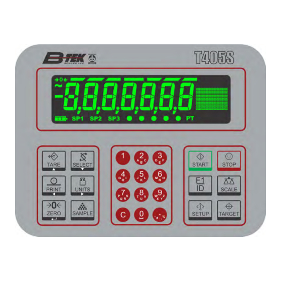
PLC's and scoreboards. See the Specification literature for a full list of specifications. Figure 2.1 Front panel of the T405S indicator The T405S can connect to USB flash drives, printers, remote displays, computers and other peripheral devices. T405S Indicator Service Manual... -
Page 14: Front Panel
Never press a key with anything but your finger. Damage to the overlay may result if sharp or rough objects are used. The normal function of the keys on the front panel of the T405S are listed below. Press the TARE key for pushbutton, key entry or preset Tare functions. -
Page 15: Front Display
Use the numeric keypad to enter numbers in the appropriate screens. Press the C (CLEAR) key to clear the last entry. 2.1.1 Front Display bargraph center-of-zero graphic motion display area battery status setpoints custom annunciators Ethernet preset tare activity T405S Indicator Service Manual... -
Page 16: Powering Up The T405S
Then to enter a negative number, with a single 0 displayed press SELECT. The first character will then change to a (-) negative sign. Enter the rest of the digits normally. To enter a decimal point (or comma), on a T405S use the decimal point key. 2.5 String index/character data entry Below are guidelines to create or edit text and scale information for print formats. - Page 17 Delete flashing Single Key Press flashing digit by the flashing Enter Add Digit ESC/Abort digit digit by 1 Move flashing Move flashing Delete the Long Key Press Enter Does nothing ESC/Abort digit left digit right entire entry T405S Indicator Service Manual...
-
Page 18: Chapter 3 Introduction To The Menus
Press UNITS/ to move right in a menu Press ZERO/ to accept a value or choice and move up in the menu. Press F1 to escape and move up in the menu T405S Indicator Service Manual... -
Page 19: Accessing The Menus
SAVEYES and CAnCEL. Press ZERO to accept the displayed choice. If you choose SAVE no or SAVEYES the indicator exits the menu and returns to normal weighing mode. If you choose CAnCEL, the indicator remains in the menu. T405S Indicator Service Manual... -
Page 20: Menu Annunciators
This means you are in a data entry. See String index/character data entry on page 16 for more information. Every alternate segment flashing This means you are in octet entry for IP, Subnet or Gateway address. T405S Indicator Service Manual... -
Page 21: Quick Code Parameter Entry
1.2.1.9 Dvision Units Stable Filter Ranges 2,3,Range Type Capacty 1.1.1 1.1.2 Scale 1 Scale 2 1.1.1.1 1.1.1.2 1.1.1.3 1.1.1.4 1.1.1.5 1.1.1.6 1.1.1.7 1.1.1.8 Zero Span Linear Input Gravity Cal.Unit Print Display Figure 3.1 Quick Code table T405S Indicator Service Manual... -
Page 22: Chapter 4 User Level Menus
Reference Using the al- d- x phanumeric keypad Figure 4.2 User menu Use this menu to set the time, date, site ID, to see the physical seal status and print archive information. Each is explained below: T405S Indicator Service Manual... -
Page 23: Time
Use the dAtE item to set the year, month and day and the style of the displayed date. Enter values for the date. y- x = Year m- x = Month d- x = Day T405S Indicator Service Manual... -
Page 24: Site Id
See the note below. The seal switch jumper, E7, is located in the top left quadrant of the main PCB. See T405S jumper and switch settings on page 144. If the jumper is installed, the indicator is sealed. -
Page 25: About Menu
Use this menu to display information about the various items shown in Figure 4.3. Each is explained below: Definitions: Bootloader Software that makes the electronics run. Firmware Embedded system software that creates core functions of the product. Specific software that controls the behaviour for a given installation. T405S Indicator Service Manual... -
Page 26: Boot (Bootloader)
Use this to view the Serial Number of the indicator. The Serial number is displayed in two parts. Press RIGHT arrow key or LEFT arrow key to toggle the display between the (View SN) xxxx xxxxx first and second parts of the serial number. T405S Indicator Service Manual... -
Page 27: Enet
About menu 4.2.5 Option Bus 1 There is only 1 Bus in the T405S. Option Card 1 There is only 1 Card in the T405S. Bus 1 oPtion Use this to view the description and version of an installed option card. -
Page 28: Download
View the serial number of the cell that is connected. cAL.SEr View the serial number of the cell that WAS connected at the time of calibration. To exit the menu, see Exiting the menus on page T405S Indicator Service Manual... -
Page 29: Audit Menu
Use this to view these items: Counter conFig View how many times the indicator has been Config Calib configured. Displays Displays cALib View how many times the number of number of indicator has been calibrations configurations calibrated. T405S Indicator Service Manual... -
Page 30: Print
Printing to USB requires that a USB flash drive is connected to the indicator host USB. Printing to USB will create a folder on the flash drive and a comma separated file with the data. To exit the menu, see Exiting the menus on page T405S Indicator Service Manual... -
Page 31: Chapter 5 Diagnostics Level Menus
The and symbols stand for direction moved in the menu. So Diag Scale illustrates that you move down from Diag to Scale. This will help you keep track of where you are in the menu structure. Each of the items in the Diag menu is explained below: T405S Indicator Service Manual... -
Page 32: Scale
Clear the zero offset to return the indicator to calibration zero. Choose Yes or No. This can restore the original calibration zero point if the ZERO key is accidently pressed when a tank or vessel contains product that cannot be emptied. T405S Indicator Service Manual... -
Page 33: Display
PASS or FAiL, depending on if the USB device is working correctly or not. If no USB device is plugged in when you begin the test, oPEn is briefly displayed, then no uSb is briefly displayed, then uSb. T405S Indicator Service Manual... -
Page 34: Inputs
CAUTION: Be sure to take proper precautions to ensure material controlled by the scale outputs will not create a hazardous condition during an output test. WithoutPutS is displayed, press SELECT … outPut1 is displayed. Press SELECT … o.1-oFF is displayed. T405S Indicator Service Manual... -
Page 35: Options
LogS These are logs of various functions. You can print or clear them from memory. Print Choose to print the log from Port 1 or Port 2. cLEAR Choose to clear the log from memory. T405S Indicator Service Manual... -
Page 36: Bsq
The tension and compression frequencies should each be as stable as the other and within 10% of each other. As weight increases the tension frequency should increase and the compression frequency should decrease. This completes the Diag menu. To exit the menu, see Exiting the menus on page T405S Indicator Service Manual... -
Page 37: Chapter 6 Admin Level Menus
The top level items in the Setup menu are shown in Figure 6.2. Setup Calib Scale System Ports See page See page See page See page Figure 6.2 Setup menu (password 3088) Each of the items in the Setup menu are explained in the following sections. T405S Indicator Service Manual... -
Page 38: Calibration Procedure
Using the alphanumeric keypad on page 6.2.1 Scale 1-2 Select the scale to be calibrated, Scale 1 or Scale 2. The Number of Scales on page must be set to 2 to access Scale 2 settings. T405S Indicator Service Manual... -
Page 39: Zero Procedure
Cal Zero value. Continue to the SPAN procedure without removing the test weights. Key in the value of the test weights on the scale and complete the SPAN procedure. The test weights will now read accurately. T405S Indicator Service Manual... -
Page 40: Span Procedure
Place Pt 9 Place Pt 2 weight on weight on scale. scale. Live weight Live weight displayed. displayed. LinEAr Add up to eight additional calibration points to improve the linearity performance of the scale. T405S Indicator Service Manual... -
Page 41: Input Procedure
Use this to enter a span using a mV/V value. The BSQ base only allows entry of Counts for Zero or Span points The Span value is the differential value of the actual Calibration Zero and Span count (or mV/V) values. T405S Indicator Service Manual... -
Page 42: Gravity Factor Procedure
Be sure to save the changes when you exit the menu and test the accuracy with a known weight. CAUTION: Verify with local agencies if adjusting the gravity factor is accepted in your area. It may be required that calibration be done with certified weights. T405S Indicator Service Manual... -
Page 43: Display
Port 1 Port 2 in the future to restore calibration. Calibration report on page 109 view a representation of the printed report. This completes the Calib menu. To exit the menu, see Exiting the menus on page T405S Indicator Service Manual... -
Page 44: Scale
String1 Key in Edit value string Not for Unit 2 Unit 3 Unit 4 Unit 1 Unit 1 1000 g Lb-oz Cust 1 Cust 2 Cust 3 Cust 4 0.000001 0.000002 0.000005 Figure 6.4 Scale menu T405S Indicator Service Manual... -
Page 45: Scale 1-2
0.0001, 0.0002, 0.0005, 0.001, 0.002, 0.005, 0.01, 0.02, 0.05, 0.1, 0.2, 0.5, 1, 2, 5, 10, 20, 50, 100, 200 and 500. The default value is 1. Division sizes for other units of measure are automatically calculated by the indicator. T405S Indicator Service Manual... -
Page 46: Units
Use this to enter a string label for the custom unit. Refer to String index/character data entry on page 16 for instructions on how to enter a string label. This is only used when data is transmitted out one of the communication ports. T405S Indicator Service Manual... -
Page 47: Stable
Set the time window in seconds. 1 second is the default value. Set to 0 to disable AZT. In certain applications, such as when batching product that starts falling slowly onto the scale, it may require disabling AZT or changing the default values to reduce the effect. T405S Indicator Service Manual... -
Page 48: Filter
Go to step 3. Repeat step but increase AVg by 10. Keep repeating steps until the scale is stable or you’ve tried an Average value up to 80. If the scale is still not stable go to step 4. T405S Indicator Service Manual... -
Page 49: Ranges
See the items below. bASis Use this to choose what the over and under capacity function is based on. PErcEnt Use this to choose to base over/ under capacity on a percent. T405S Indicator Service Manual... -
Page 50: 2,3,Range
Multi-range - the division size will change as it enters a new weight range on increasing weight but will not change back to the smaller division size until the display returns to Zero. This is the default setting. T405S Indicator Service Manual... -
Page 51: Type
If you choose oPtion , this selection requires a bus and card number. For the T405S indicator, only one option card can be installed so these values are already defaulted to bus 1 and card 1 and do not need to be configured. -
Page 52: Roc
Period Enter a value for the period of time to calculate of time to time ROC. calculate Units Enter the units for the time: Seconds , Minutes or Hours . This completes the Scale menu. T405S Indicator Service Manual... -
Page 53: System
Print Units Select Tare Zero Target Start Stop SclSel Setup NumPad Dec.Pt Update M-dash C-zero Tot Scl 0.25 0.50 Decimal Comma CHINA INDIA Figure 6.5 System menu Items in bold boxes and text are default values. T405S Indicator Service Manual... -
Page 54: Default Values
DD-MM-YY DD-MM-YY DD-MM-YY DD-MM-YY Time Format 12 Hr Average Filter Constant Filter Threshold Under Cap. Div. AZT Time AZT Div. Motion Time Motion Div. Default settings may need to be changed to meet local agency requirements T405S Indicator Service Manual... -
Page 55: Site
Choices are 1 , 2 , 5 , 10 and 20 . Lowering the update rate can sometimes improve stability of the display in noisy environments, e.g. vibration or wind. m-dASh If enabled, the display will show dashes during motion. T405S Indicator Service Manual... -
Page 56: Buttons
Follow the same procedure for each key to turn it on or off. on is the default value for all the buttons. The complete list of buttons for the T405S is shown in the menu above. 6.4.5 Display values D-vals... - Page 57 Activate this to see the net maximum value. FFALL 1 Activate this to see the free fall 1 value. Free fall is like preact. This is the calculated amount of material that will fall on the scale base on the current flow rate. T405S Indicator Service Manual...
- Page 58 Activate this to see the rate of change (ROC). uSEr Activate this to see user message programmed through a custom application. VArMSg Activate this to see user message programmed through a custom application. T405S Indicator Service Manual...
-
Page 59: Tare
If preset tare is enabled, pushbutton tare and keyboard entry tare will be disabled automatically. Preset Tares are entered in the Supervisor menu. See the User manual. T405S Indicator Service Manual... -
Page 60: Config
The indicator has memory capacity to store approximately 5,000 transactions. The Archive report uses a rolling memory configuration (FIFO) so the oldest transaction will be written over first when all the memory slots are filled. T405S Indicator Service Manual... -
Page 61: Serial
FTP to the indicator and is waiting to update. If you choose no , no update occurs and MAnuAL is displayed. If you choose YES , the indicator will update and reboot. T405S Indicator Service Manual... -
Page 62: Password
Z-LocK PrESS ZEro . The operator must press ZERO to unlock the indicator. EnAbLE oFF or on . oFF is the default. timE Use this to set the time value, in minutes, for this function. 60 minutes is the default T405S Indicator Service Manual... -
Page 63: Beeper
Use this to key in the number of scales attached to the scale. To access settings for Scale 2 and to use the SCALE key this must be to 2. Default is 1. This completes the System menu. T405S Indicator Service Manual... -
Page 64: Ports
Select only Port1-2 Port1-H Client Server Clnt2 None Hard Soft Port 1 only None Even 1200 2400 4800 9600 19200 38400 57600 115200 Figure 6.6 Ports menu Items in bold boxes and text are default values T405S Indicator Service Manual... -
Page 65: Serial
Hardware flow control on Port 1 is only available if Port1-H is selected and Jumper P5 is in position 1. See the photo in section T405S jumper and switch settings on page 144. T405S Indicator Service Manual... -
Page 66: Ethernet
Key in each octet and press ZERO to accept it. Typically devices within a network share the same address for the first three octets (network address) and each device will have a unique setting or value for the fourth octet (device address). T405S Indicator Service Manual... - Page 67 Host IP Address is only used if the Type setting is Client for this port connection. If Type is set to Off Type x is the only item listed under E-Net x . You must choose one of the other choices to see other items listed. T405S Indicator Service Manual...
- Page 68 If set to Off then all messages will be sent to the IP address specified by the TxAdd x setting. Default is Off . T405S Indicator Service Manual...
-
Page 69: Protocol
Choose this to disable the selected protocol. Print Choose this when you want to press the PRINT key or when using Autoprint to send the data through the selected binding (Port) using the associated attributes. T405S Indicator Service Manual... - Page 70 Secondary indicator. Choose this to use the NCI communication protocol. See NCI commands on page 85 rEPortS Choose this for reports using footers and headers. Choose this when using a BSQ base. T405S Indicator Service Manual...
- Page 71 Archive reporting to add the transaction record and increment the counter. The default value is 7 (ASCII BEL character). Choices are 0 to 255. ScALE If multiple scales are enabled, select the scale number this attribute is assigned to. T405S Indicator Service Manual...
-
Page 72: P.f.edit
Ethernet IP. Choose M tcP to enable Modbus- TCP. EndiAn Choices for this item are big or LittLE . Default is LittLE . ENDIAN: Big = Most Significant Byte, Least Significant Byte Little = Least Significant Byte, Most Significant Byte T405S Indicator Service Manual... - Page 73 Key in the value for the network token you want from the table above and press ZERO to accept the displayed choice … Repeat the process for any other inbound memory registers you want to configure. ScALE Choose from connected scales. T405S Indicator Service Manual...
-
Page 74: Printer
ZEbrA , EPSnPoS , hP 14-- , hp15-- and hp85-- . bind Choices under this item are: Port 1 , Port 2 and EnEt 1 through EnEt 5 . Choose which port the printer output is attached to. T405S Indicator Service Manual... -
Page 75: File
Use this to configure the file convention. Choices are: conStAn This will create a single file that will be appended to as new information is saved. nuMbrd This will create new file appended with a sequential number for each transaction. T405S Indicator Service Manual... - Page 76 Numbered file will be created. If using the Date & Time file naming convention then individual files will be created. rESEt Reset will clear all stored transactions and also reset the numbered file sequence to 000001. T405S Indicator Service Manual...
-
Page 77: Options
5VDC Excitation Analog Scale Input card 10VDC Excitation Analog Scale Input card The Ext io menu item is for the following I/O interface card: External I/O Interface card AC Input 4 relays (120-240VAC) card DC Input 4 relays (4-30VDC) card T405S Indicator Service Manual... - Page 78 SELECT decrease in small increments PRINT increase in large increments UNITS decrease in large increments Press ZERO to complete the analog output calibration The Analog Output requires a Bind setting of oPtion T405S Indicator Service Manual...
- Page 79 The 802.11 wireless option requires the same setup as an Ethernet port and a Bind setting of E-Net 1 through 5 based on the Ethernet setup. The External I/O and AC/DC Inputs/Outputs options require Ztools to configure This completes the service menus for the T405S indicator. See Exiting the menus on page 19 to save the setup and return to normal weigh mode.
-
Page 80: Chapter 7 Communication Port Protocols
See “Scale Information Command Response” Information data. (for the current scale) (below) <ESC> The indicator will reboot itself None SMA protocol is maintained by an external organization. For definitive and current details on this protocol go to www.scalemanufacturers.org. T405S Indicator Service Manual... -
Page 81: Standard Scale Response Message
1st response: <xxx> = “SMA” <yyyyy> = compliance level/revision 2nd response: <xxx> = “MFG” <yyyyy> = manufacturer 3rd response: <xxx> = “MOD” <yyyyy> = software part number 4th response: <xxx> = “REV” <yyyyy> = software revision T405S Indicator Service Manual... -
Page 82: Scale Information Command Response
<yyyyy> = “PTMCU” list of supported SMA commands. Level 1 commands are not included in the list. 6th response: <xxx> = “END” <yyyyy> = nothing 7th & more - responses: Subsequent N commands will return a ‘?’ response. Unrecognized Command Response T405S Indicator Service Manual... -
Page 83: B-Tek Extended Sma Commands
The list above includes all the keys for all the various models of Z indicators. If your model of indicator does not have one of these keys, that key will not be included in the returned list. XD, XZ and XS commands, below, only work if the indicator is unsealed. T405S Indicator Service Manual... - Page 84 XVS command was successful requires sending the XVG command to confirm the value of the variable. <LF>XVG<n><CR> The indicator will get or return the value of the variable specified by the network token. A valid response is in the form of <LF><value><CR>. T405S Indicator Service Manual...
-
Page 85: Enq & B-Cast Commands
Returns normalized raw counts and scale status. T <Cr> Tare request Scale is Tared and returns scale status. all else Unrecognized command Returns <Cr> ? <Lf> See Additional token tables for status byte information. on page 128 T405S Indicator Service Manual... -
Page 86: R-Disp Commands
Change to oz grams Change to grams Outgoing key press commands from the Remote display that control the Master indicator operation TARE SELECT ZERO PRINT UNITS Key press commands are supported by COM Port 1 and 2 only. T405S Indicator Service Manual... -
Page 87: Plc Configuration Information
30001 (Mirrored at the Read/Write Locations) Input Read/Write 40001 Output Read/Write 41025 2 Byte Example Indicator Data Type (out) ModBus Register SINT16 41025 SINT16 41026 4 Byte Example Indicator Data Type (out) ModBus Register SINT32 41025 SINT32 41027 T405S Indicator Service Manual... - Page 88 Note each register holds 2-bytes or 1-word. If a 4-byte or 2-word data type is used 2- registers are required for each item. This makes the starting register number for each item skip a register number between items. T405S Indicator Service Manual...
-
Page 89: Ethernet/Ip Implicit Messaging
Indicator Output (Out) (hex value) Configuration Data Data Element Location 0 x 0E (Get Attribute Single) Based on network configuration in 1-16 (Bound to the instance x) 1= First Element indicator. See DATA TYPE TABLE 2=Second Element T405S Indicator Service Manual... -
Page 90: Chapter 8 Option Cards
8 Option cards Option cards The T405S has several option cards available. Only one card can be installed in the indicator. This chapter covers the description and installation of these cards: Analog output card on page 92 Current Loop/RS485/RS422 card... - Page 91 J4. Screws, at the four locations noted by the arrows, hold the board in place. Connector pins on bottom of the card. Figure 8.1 Option card example T405S Indicator Service Manual...
-
Page 92: Analog Output Card
Figure 8.2 Analog output option card CAUTION: The output will run to the minimum value when a fault occurs and when you enter the Setup menus, so plan accordingly! Function V out Common (GND) I out T405S Indicator Service Manual... -
Page 93: Current Loop/Rs485/Rs422 Card
20ma RCV Input 20ma RCV Return P2 - Jumper On = RCV Sinking P2 - Jumper Off = RCV Sourcing P1 - Jumper On = Terminated P1 - Jumper Off = Unterminated Figure 8.3 Current Loop/RS485/RS422 card T405S Indicator Service Manual... -
Page 94: Usb Device Option Card
PC it creates a Virtual COM Port (VCP). Be sure to make note of the COM port number assigned to the VCP when setting up the serial communication application. Connections to USB Device option card include USB Type B and Mini connectors. T405S Indicator Service Manual... -
Page 95: Device Nettm Option Card
TB1 Pinout Device Net Pluggable Connector TB1 Pin No. Signal V- (Bus power GND) CAN_LOW Shield CAN_HI V+ (+24VDC)* *An external power supply will be used to supply V+ power. Typically this supply will be previously installed. T405S Indicator Service Manual... -
Page 96: Software Controlled Baud Rate
+ 2.5 X L = 250 at 250K baud thick thin = 100 at 5005K baud thick thin where L is the length of thick cable and L is the length of thin cable. thick thin T405S Indicator Service Manual... -
Page 97: Profibus
Profibus DP DB-9 based connector cabling and TB1 is for flying lead wiring internal to the ZM Indicators enclosure. +5V and GND are used for external bus termination if the internal S2 termination resistors are not used. T405S Indicator Service Manual... -
Page 98: S2 Switch Settings
8 Option cards 8.5.1 S2 switch settings: On = Termination resistors Enabled/Present (Default Position) Off = Termination resistors Disabled/Removed T405S Indicator Service Manual... -
Page 99: Wireless Ethernet Communication (802.11G) Card
Wireless Ethernet communication 802.11g card. This provides wireless Ethernet connectivity via the 802.11g protocol.. S1 switch settings must all be OFF to operate. Figure 8.7 802.11g wireless communication option card Figure 8.8 802.11g wireless communication antenna and connection point T405S Indicator Service Manual... -
Page 100: Internal 120 Vac Relay Card (For Ip69K Only)
This option card is capable of switching up to 1Amp Max. per channel at 20- 120VAC. Please refer to the appropriate National Electrical Code regulations with regards to the switched AC mains voltage wiring sizes and insulation requirements. T405S Indicator Service Manual... -
Page 101: Installing The Option Card
Option card TB1 pin 7 (OUT3) and the Main Board TB2 pin 7 (OUT3) : SP3 These wires are shown in place in Figure 8.10. The use of Ztools is typically required to configure the AC Relay option card T405S Indicator Service Manual... -
Page 102: 2Nd Scale Input 5Vdc Excitation Card
+SEN -SIG +SIG SHLD SENSE Excitation Jumpers 4 wire loadcells requre jumpers to be ON the pins. 6 wire loadcellss require jumpers to be OFF the pins. Figure 8.11 5VDC Excitation Analog Scale Input option card T405S Indicator Service Manual... -
Page 103: 2Nd Scale Input 10 Vdc Excitation W/Stvs Card
SENSE Excitation Jumpers protection. 4 wire loadcells requre jumpers to be ON the pins. 6 wire loadcellss require jumpers to be OFF the pins. Figure 8.12 10VDC Excitation Analog Scale Input option card T405S Indicator Service Manual... -
Page 104: External I/O Interface Card
P3 is for connecting a ribbon cable to an external 16 position I/O board (J1) AWT05-508727 TB2 is for connecting to an external SSCU8 board (TB35) AWT05-508726. The use of Ztools is required to configure the External I/O option card. T405S Indicator Service Manual... -
Page 105: Ac Input, 4 Inputs (120-240Vac) Card
CAUTION: For safety reasons the AC Input option card can only be used in the primary earthed stainless steel enclosure. 120-240 VAC <10mA AC Plug Neutral Ground AWT25-501903 PCBA The use of Ztools is required to configure the AC Input option card. T405S Indicator Service Manual... -
Page 106: Dc Input, 4 Inputs(4-30Vdc) Card
S1 switch settings must all be OFF to operate. Function IN1- IN1+ IN2- IN2+ IN3- IN3+ IN4- IN4+ <50mA 4-30 VDC AWT25-501899 PCBA The use of Ztools is required to configure the DC Input option card. T405S Indicator Service Manual... -
Page 107: Ac Output, 4 Relays (20-240Vac) Card
I = 1 Amp M ax Neutral Neutral Ground Ground AC Load AWT25-501901 PCBA AWT25-501901 PCBA 20-240 VAC 1 Amp Max Figure 8.14 Wiring examples The use of Ztools is required to configure the AC Output option card. T405S Indicator Service Manual... -
Page 108: Dc Output, 4 Relays (3-60Vdc) Card
Function SP1- SP1+ SP2- SP2+ SP3- SP3+ SP4- SP4+ 3-60 VDC = 2 Amps MAX Load AWT25-501894 PCBA Ground Figure 8.15 Wiring example The use of Ztools is required to configure the DC Output option card. T405S Indicator Service Manual... -
Page 109: Chapter 9 Printed Reports
SCALE_1_SPAN_FACTOR Value = 0.00000909 SCALE_1_GRAVITY Value = 9.8043 SCALE_1_ZERO_MV Value = 0.38003510 SCALE_1_SPAN_MV Value = 1.63769878 SCALE_1_ALTITUDE Value = 0.00000000 SCALE_1_LATITUDE Value = 0.00000000 SCALE_1_SPAN_COUNTS Value = 1099040 SCALE_1_CAL_WEIGHT Value = 10.0000000 UNIT SERIAL NUMBER Value = 20120111 T405S Indicator Service Manual... -
Page 110: Audit Report
2012-03-20 10:12:30 SCALE_1_UNIT3 2012-03-20 10:08:17 PROTOCOL_1_TYPE 2012-03-20 10:00:27 PROTOCOL_2_FORMAT_1 2012-03-20 09:14:45 SCALE_1_UNIT4 2012-03-20 09:10:35 SCALE_1_UNIT3 2012-03-20 09:10:30 SCALE_1_UNIT2 2012-03-20 09:10:27 SCALE_1_SPAN_FACTOR 0.00003265 0.00003707 2012-03-20 09:09:43 SCALE_1_ZERO_COUNTS 394685 -651448 2012-03-20 09:09:27 PROTOCOL_2_BIND 2012-03-20 09:09:14 PROTOCOL_2_TYPE 2012-03-20 09:09:12 T405S Indicator Service Manual... -
Page 111: Chapter 10 Print Formatting
The T405S indicator also supports the UTF-8 Unicode character set which is used for numerical HTML Coding values and to support many foreign language character sets. Following are tables showing the key functions in the string indexing and character editing modes. -
Page 112: Editing An Existing Print String
Number of characters to insert Decimal value to enter To center the company name on a printed ticket, you must add spaces in front of the company name. This will add to the total count of characters to insert. T405S Indicator Service Manual... -
Page 113: Inserting Characters
Enter the decimal value for the next letter in the company name and press ZERO . Repeat steps until the last character is entered. In this example that would be 13, 10 for the line feed. T405S Indicator Service Manual... -
Page 114: Deleting Characters
Gross 3000 lb Tare 1000 lb 2000 lb T.GWT T.UNIT T.SAT T.UNIT T.NWT T.UNIT From P.F.Edit press SELECT … PrnFt1 is displayed. Press SELECT … The first character in the print format will be displayed: GROSS T405S Indicator Service Manual... - Page 115 At any time during a string edit you can press F1 to abort the print format editor without affecting the existing print string. This allows for an ESCAPE if you think you may have made an error during the editing process. T405S Indicator Service Manual...
-
Page 116: Inserting Tokens, Etc
Add appropriate spacing in front or after as needed for proper alignment in the printed data. The value 1 in the above screen will be whatever index value you started from. T405S Indicator Service Manual... - Page 117 The value of the number in this next location identifies what function of the token is being used. Decimal 1 = 49 is the actual Gross weight value. Decimal 2 = 50 is the token name, “Gross”, applied to that token T405S Indicator Service Manual...
-
Page 118: Other Scale Tokens
[ = t501 indicates the start of an optional parameter 68 = D for decimal point parameter 50 = 2 for hide decimal point ] = t502 indicates the end of the optional parameter T405S Indicator Service Manual... -
Page 119: Transmitting Leading Zeroes
49 = 1 for use leading zeros ] = t502 indicates the end of the optional parameter For more examples of editing formats consult Print tokens, parameters and default print formats on page 121 T405S Indicator Service Manual... -
Page 120: Print Format Errors
Aspect data invalid, codepoint is NOT 1, 2 or 3 Invalid UTF8 string Left parameter bracket not found Right parameter bracket not found Dot separator not found Token tag string is invalid UTF8 codepoint to large Token to large Error within optional parameter T405S Indicator Service Manual... -
Page 121: Chapter 11 Print Tokens, Parameters And Default Print Formats
TONS you will need to use the WIDTH syntax as follows to have all 3 letters printed to spell TON { T.UNIT.1[W3]} DEFAULTS: Pounds = lb Kilograms = kg Grams Ounces = oz Pounds/Ounces = lb-oz Custom = (first 2 letters) T405S Indicator Service Manual... -
Page 122: Firmware Tokens
0 = Current Scale LSTSTBL Last Stable Weight Last Stable Weight Scale 1 = Scale 1 2 = Scale 2 Percent Percent Target Weight Target GWTPC Gross Total + Current Gross Weight Gross Total + Current T405S Indicator Service Manual... - Page 123 Gross Total All Scales Totals Gross Total All Scales NATAS Net Total All Scales Totals Net Total All Scales TATAS Tare Total All Scales Totals Tare Total All Scales CATAS Count Total All Scales Totals Count Total All Scales T405S Indicator Service Manual...
- Page 124 1 = None 2 = Comma (,) 3 = Period or Decimal Point (.) 4 = Backslash (\) Separator 5 = Space ( ) 6 = Forward Slash (/) 7 = Colon (:) 8 = Dash (-) (default) T405S Indicator Service Manual...
- Page 125 56 = Start Xmodem 57 = Start Sum 16 58 = Start Sum 8 59 = Start CRC 16 (FFFF) 60 = Start Inverse IRCC 8 61 = Start Sum 16 (W/O Twos) 62 = BCC T405S Indicator Service Manual...
- Page 126 Combinations of these errors can also occur. (e.g., “3 = Range error (2) plus Motion (1)) NAME Indicator Scale Name Scale Name 32 characters max entered in Ztools under SYSTEM TAB Indicator Scale Location Scale Location T405S Indicator Service Manual...
- Page 127 Print Format Italic Format Italic “<ESC><ESC>I” UNDR Print Format Underline Format Underline “<ESC><ESC>U” LAND Print Format Landscape Format Landscape “<ESC><ESC>L” Print Format Form feed Format Form Feed “<ESC><ESC>F” WRAP Print Format Line Wrap Format Line Wrap “<ESC><ESC>W” T405S Indicator Service Manual...
-
Page 128: Additional Token Tables
Bit 7 1 = Byte follows 1 = Byte follows Always 0 0 = Last Byte 0 = Last Byte Example: Stable and valid gross weight in lb unit of measure would return "822" Parity Parity Parity T405S Indicator Service Manual... -
Page 129: Network Tokens
BYTE #1: Bit 0 = Any Fault Indicator Healthy Status (2-Byte) Bit 1 = ADC Error Bit 2, 3, 4 = N/A Bit 5 = Overload Condition Bit 6 = Underload Condition Bit 7 = N/A T405S Indicator Service Manual... - Page 130 Remote PB Accumulate Key toggle the register every time the XOR is executed. Remote PB Units Key * the “Low Weight Value” and “High Weight Value” only apply when the Output mode selection is Act-In or Act-Out T405S Indicator Service Manual...
-
Page 131: Ascii Characters
0165 0210 0255 0127 & & 0166 0211 0167 0212 0168 0213 0169 0214 0170 0215 0171 0216 0172 0217 T405S Indicator Service Manual... -
Page 132: Control Codes
#DC2 Device Control 3 #DC3 Device Control 4 #DC4 Negative Acknowledge #NAK Synchronous Idle #SYN End of Block #ETB Cancel #CAN End of Medium Substitute #SUB Escape #ESC File Separator Group Separator Record Separator Unit Separator T405S Indicator Service Manual... -
Page 133: Default Print Formats
T.ACT T.UNIT and Displayed {T.ACT.2[W1]} {T.ACT.1} {T.UNIT.1}#CR#LF t501 t502 Weight Displayed T.ACT T.UNIT T.ACT Weight and {T.ACT.2[W1]} {T.ACT.1} {T.UNIT.1}#CR#LF t501 t502 Active value High Resolution T.GWTHR Gross weight {T.GWTHR.1[r2W8]} t501 t502 (typically used for Analog option) T405S Indicator Service Manual... - Page 134 T405S Indicator Service Manual...
-
Page 135: Chapter 12 Complete Menu Structures
Comp. freq Tension freq installed Serial1 Serial2 on and off counts or mV/V displayed displayed Scale 1 Scale 2 Print Clear options Loopback Loopback Performs Clr no Clr yes test test write/read Value Clear test Port1 Port2 T405S Indicator Service Manual... - Page 136 X.X.X.XX number number Partno Version Subnet Gateway Displays the (View version) bootloader PN X.X.X.XX AWT30 XXXXX 2 xx 2 xx 2 xx 2 xx Bus 1 Card 1 Type Version (View card (View card description) version) T405S Indicator Service Manual...
- Page 137 Press UNITS / to move right in a menu Press ZERO / to accept a value or choice and move up in the menu. Press F1 to escape and move up in the menu T405S Indicator Service Manual...
- Page 138 Cust 1 Cust 4 Ratio1 String1 Key in Edit value string Unit 2 Unit 3 Unit 4 Not for Unit 1 Unit 1 1000 g Lb-oz Cust 1 Cust 2 Cust 3 Cust 4 0.000001 0.000002 0.000005 T405S Indicator Service Manual...
- Page 139 Pcwt IK Per Ac Lst Smp User Var Msg Print Units Select Tare Zero Sample Target Start Stop SclSel Setup NumPad Dec.Pt Update M-dash C-zero Tot Scl Defaults vary with application 0.25 0.50 Decimal Comma CHINA INDIA T405S Indicator Service Manual...
- Page 140 2 xx 2 xx 2 xx Port 1 Baud D-Bits Parity S-Bits C-trol Select only Port1-2 Port1-H Client Server Clnt2 None Hard Soft Port 1 only None Even 1200 2400 4800 9600 19200 38400 57600 115200 T405S Indicator Service Manual...
-
Page 141: Chapter 13 Technical Illustrations
13 Technical illustrations ITEM DESCRIPTION OVERLAY KEYPAD, MODEL T405S 13.1 T405S assembly PAD, NEOPRENE-1.00 DIA KNOB, 4 LOBE-M6 STAND, ENCLOSURE T405S LOSKID7/16"HEX,1/16"THK W/9672 BRACKET, PC BOARD T405S NUT,M4 W/EXT LOCK WASHER SST CABLE ASSY MAIN/DSPL INTFC PCB ASSY, MAIN STANDOFF, HEX M3 x 0.5mm x 14mm M/F SST... -
Page 142: T405S Parts Kits
13.2 T405S parts kits AWT05-506055 - Universal Hardware Kit Stainless steel enclosure parts AWT05-506052 - SS Hardware kit Qty. Description Item # Item # Description Qty. Description Qty. (page 141) (page 141) LOSKID7/16"HEX,1/16"THK W/9672 SPACER,RD-3.2MMID X 3.0MM LG AWT20-505480 STAND, ENCLOSURE PAD,NEOPRENE-1"DIA... -
Page 143: System Block Diagram
Com 1 & 2 RS232 Description Description Description -EXC +EXC Input 1 -SEN Input 2 RTS / TX2 +SEN Input 3 -SIG Digital Out 1 CTS / RX2 +SIG Digital Out 2 5VDC SHIELD Digital Out 3 Relay Voltage T405S Indicator Service Manual... -
Page 144: T405S Jumper And Switch Settings
13.4 T405S jumper and switch settings T405S Main PC board Model Select Switch See the settings for these switches in the System block diagram on page 143 Flow control jumper Sense (Excitation) jumpers shown in the unjumpered position. Jumper shown in position 2 (default) for 2 comm 4 wire loadcells require jumper. -
Page 145: T405S Remote Inputs And Outputs, Opto-22 Module
13.5 T405S remote inputs and outputs, Opto-22 module USING EXTERNAL DC VOLTAGE USING INTERNAL +5VDC VOLTAGE USING INTERNAL +24VDC VOLTAGE TO OPERATE RELAYS TO OPERATE RELAYS TO OPERATE RELAYS (TB2) (TB2) (TB2) (TB3) (TB5) CUTOFFS (TRIPS) CONNECTOR CUTOFFS (TRIPS) CONNECTOR CUTOFFS (TRIPS) CONNECTOR COM 1 &... -
Page 146: Stvs (Severe Transient Voltage Suppressor) Installation
Scale Interface Cable To TB1 +SEN -SEN -SIG +EXC +SIG -EXC WHT/ORG -SHIELD IN side STVS module orientation should be vertical with the side marked IN towards the bottom of the indicator, closer to the Gore Vent. T405S Indicator Service Manual... -
Page 147: Outline Dimensions
13.7 Outline dimensions T405S Indicator Service Manual... -
Page 148: External Battery Circuitry
External battery circuit If you use an external battery for power and wish to take advantage of the auto off function, follow the suggested circuit illustration below. External Battery Power 0.20A + RLY ZM - Output #3 T405S Indicator Service Manual... -
Page 149: Keypad Overlay Replacement Procedure
Let the enclosure dry for at least 5 minutes. Place new keypad on the enclosure; ensure that the keypad is aligned correctly. Use rolling pin on the overlay to ensure good contact between the enclosure and the keypad overla T405S Indicator Service Manual... - Page 150 T405S Indicator Service Manual...
-
Page 151: Index
Automatic zero tracking (AZT)... 47 Division AWT Extended SMA Commands... 83 scale menu... 45 Bootloader... 25 Edit an esisting print string... 112 Button test... 33 ENQ and B-Cast commands... 85 Error log report... 35, 36 Errors print format... 120 T405S Indicator Service Manual... - Page 152 Mainboard jumper settings... 144 format editor... 111 Mainboard switch settings... 144 format errors... 120 Menu access... 19 insert tokens... 116 Menu annunciators... 16 transmit leading zeroes... 119 Menu level... 18 Print calibration report... 43 Menu navigation keys... 18 T405S Indicator Service Manual...
- Page 153 ZM305 main PC board... 144 Stability... 47 Stainless steel enclosure assembly... 141 Stainless steel enclosure parts kits... 142 String index/character data entry... 16 STVS voltage suppressor... 146 Switch settings... 144 System block diagram... 143 System menu... 53 T405S Indicator Service Manual...
- Page 154 T405S Indicator Service Manual...
- Page 156 B-TEK Scale LLC 1510 Metric Ave. SW Canton, OH 44706-3088...