Dell OptiPlex Micro Plus 7010 Owner's Manual
Hide thumbs
Also See for OptiPlex Micro Plus 7010:
- Owner's manual (126 pages) ,
- Owner's manual (126 pages) ,
- Owner's manual (151 pages)

Related Manuals for Dell OptiPlex Micro Plus 7010


Summary of Contents for Dell OptiPlex Micro Plus 7010
- Page 1 OptiPlex Micro Plus 7010 Owner's Manual Regulatory Model: D15U Regulatory Type: D15U001 March 2023 Rev. A00...
- Page 2 A WARNING indicates a potential for property damage, personal injury, or death. © 2023 Dell Inc. or its subsidiaries. All rights reserved. Dell Technologies, Dell, and other trademarks are trademarks of Dell Inc. or its subsidiaries. Other trademarks may be trademarks of their respective owners.
-
Page 3: Table Of Contents
Contents Chapter 1: Views of OptiPlex Micro Plus 7010................6 Front....................................... 6 Back......................................7 Chapter 2: Set up your computer....................8 Chapter 3: Specifications of OptiPlex Micro Plus 7010..............12 Dimensions and weight..............................12 Processor..................................... 12 Chipset....................................15 Operating system................................16 Memory....................................16 Memory matrix..................................16... - Page 4 Installing the side cover............................. 32 Front bezel..................................33 Removing the front bezel............................33 Installing the front bezel............................34 Solid-state drive................................35 Removing the M.2 2230 solid-state drive from slot 0..................35 Installing the M.2 2230 solid-state drive in slot 0....................36 Removing the M.2 2230 solid-state drive from slot 1..................
- Page 5 Deleting or changing an existing system setup password.................93 Clearing BIOS (System Setup) and System passwords..................93 Chapter 9: Troubleshooting......................94 Dell SupportAssist Pre-boot System Performance Check diagnostics..............94 Running the SupportAssist Pre-Boot System Performance Check..............94 Power-Supply Unit Built-in Self-Test ..........................94 System-diagnostic lights..............................95 Recovering the operating system..........................
-
Page 6: Chapter 1: Views Of Optiplex Micro Plus 7010
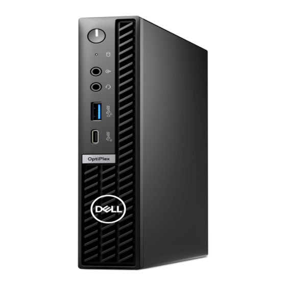
Views of OptiPlex Micro Plus 7010 Front 1. Power button with diagnostic LED 2. Hard-disk activity light 3. Re-tasking line out/line in audio port 4. Universal audio jack 5. USB 3.2 Gen 2 port with PowerShare 6. USB 3.2 Gen 2x2 Type-C port... -
Page 7: Back
4. USB 3.2 Gen 1 port with Smart Power On 5. Kensington security-cable slot and padlock ring 6. Power-adapter port 7. Service Tag label 8. Three DisplayPort 1.4a (HBR2) 9. Two USB 3.2 Gen 2 ports 10. RJ45 Ethernet port Views of OptiPlex Micro Plus 7010... -
Page 8: Chapter 2: Set Up Your Computer
Set up your computer Steps 1. Connect the keyboard and mouse. 2. Connect to your network using a cable, or connect to a wireless network. Set up your computer... - Page 9 3. Connect the display. 4. Connect the power cable. Set up your computer...
- Page 10 Follow the on-screen instructions to complete the setup. For more information about installing and configuring Ubuntu, search in the Knowledge Base Resource at www.dell.com/support. For Windows: Follow the on-screen instructions to complete the setup. When setting up, Dell recommends that you: ● Connect to a network for Windows updates. Set up your computer...
- Page 11 Dell Update, search in the Knowledge Base Resource at www.dell.com/ support. Dell Digital Delivery Download software applications, which are purchased but not preinstalled on your computer. For more information on using Dell Digital Delivery, search in the Knowledge Base Resource at www.dell.com/support. Set up your computer...
-
Page 12: Chapter 3: Specifications Of Optiplex Micro Plus 7010
Specifications of OptiPlex Micro Plus 7010 Dimensions and weight The following table lists the height, width, depth, and weight of your OptiPlex Micro Plus 7010. Table 2. Dimensions and weight Description Values Height 182 mm (7.17 in.) Width 36 mm (1.42 in.) Depth 178 mm (7.01 in.) - Page 13 Not applicable 3.30 GHz 3 GHz frequency NOTE: Processor clock speeds and thermal design power differ according to the thermal mode selected in the My Dell app on your computer. Processor cache 12 MB 12 MB 20 MB 20 MB...
- Page 14 3.20 GHz 3.70 GHz 3.40 GHz frequency NOTE: Processor clock speeds and thermal design power differ according to the thermal mode selected in the My Dell app on your computer. Processor cache 24 MB 24 MB 24 MB 24 MB...
-
Page 15: Chipset
Intel UHD Graphics 770 Intel UHD Graphics 770 Intel UHD Graphics 770 Intel UHD Graphics Chipset The following table lists the details of the chipset supported by your OptiPlex Micro Plus 7010. Table 6. Chipset Description Values Chipset Intel Q670... -
Page 16: Operating System
● 32 GB, 2 x 16 GB, DDR5, 4800 MHz, dual-channel ● 64 GB, 2 x 32 GB, DDR5, 4800 MHz, dual-channel Memory matrix The following table lists the memory configurations supported on your OptiPlex Micro Plus 7010. Table 8. Memory matrix Configuration... -
Page 17: External Ports
16 GB 16 GB 64 GB DDR5 32 GB 32 GB External ports The following table lists the external ports of your OptiPlex Micro Plus 7010. Table 9. External ports Description Values Network port One RJ45 Ethernet port 10/100/1000 Mbps USB ports ●... -
Page 18: Ethernet
Ethernet The following table lists the wired Ethernet Local Area Network (LAN) specifications of your OptiPlex Micro Plus 7010. Table 11. Ethernet specifications Description Values Model number Intel WGI219LM Transfer rate 10/100/1000 Mbps Wireless module The following table lists the Wireless Local Area Network (WLAN) modules supported on your OptiPlex Micro Plus 7010. -
Page 19: Storage
M.2 2280, Class 40, Opal Self- PCIe NVMe Up to 1 TB Encrypting solid-state drive Power adapter The following table lists the power adapter specifications of your OptiPlex Micro Plus 7010. Table 16. Power adapter specifications Description Option one Option two... -
Page 20: Gpu-Integrated
Three DisplayPort 1.4a 4096 x 2304 at 60 Hz External display support (GPU—Integrated) Table 19. External display support (GPU—Integrated) Integrated graphics card Number of supported external display iGPU option 1 + optional module iGPU option 2 Specifications of OptiPlex Micro Plus 7010... -
Page 21: Hardware Security
Hardware security The following table lists the hardware security of your OptiPlex Micro Plus 7010. Table 20. Hardware security Hardware security Kensington security-cable slot Padlock ring Chasis lock slot support Chassis intrusion switch Supply chain tamper alerts SafeID including Trusted Platform Module (TPM) 2.0... -
Page 22: Regulatory Compliance
Dell Regulatory Compliance Home page Dell and the Environment Operating and storage environment This table lists the operating and storage specifications of your OptiPlex Micro Plus 7010. Airborne contaminant level: G1 as defined by ISA-S71.04-1985 Table 23. Computer environment Description... -
Page 23: Chapter 4: Working Inside Your Computer
You should only perform troubleshooting and repairs as authorized or directed by the Dell technical assistance team. Damage due to servicing that is not authorized by Dell is not covered by your warranty. See the safety instructions that is shipped with the product or at www.dell.com/regulatory_compliance. -
Page 24: Safety Precautions
ESD protection is an increasing concern. Due to the increased density of semiconductors used in recent Dell products, the sensitivity to static damage is now higher than in previous Dell products. For this reason, some previously approved methods of handling parts are no longer applicable. -
Page 25: Esd Field Service Kit
Always place parts in your hand, on the ESD mat, in the system, or inside an anti-static bag. ● Transporting Sensitive Components – When transporting ESD sensitive components such as replacement parts or parts to be returned to Dell, it is critical to place these parts in anti-static bags for safe transport. Working inside your computer... -
Page 26: Transporting Sensitive Components
Transporting sensitive components When transporting ESD sensitive components such as replacement parts or parts to be returned to Dell, it is critical to place these parts in anti-static bags for safe transport. -
Page 27: Screw List
M.2 2230/2280 solid-state drive M2x3.5 Internal antenna M3x3 I/O module M3x3 M2x5, cross type Type-C module M3x3 Major components of OptiPlex Micro Plus 7010 The following image shows the major components of OptiPlex Micro Plus 7010. Working inside your computer... - Page 28 1. Side cover 2. Front bezel 3. Fan assembly 4. Heat sink 5. Speaker 6. Speaker holder 7. System board 8. Chassis 9. Wireless card 10. Processor 11. Memory module 12. M.2 2280 solid-state drive Working inside your computer...
- Page 29 NOTE: Dell provides a list of components and their part numbers for the original system configuration purchased. These parts are available according to warranty coverages purchased by the customer. Contact your Dell sales representative for purchase options. Working inside your computer...
-
Page 30: Chapter 5: Removing And Installing Customer Replaceable Units (Crus)
Removing and installing Customer Replaceable Units (CRUs) The replaceable components in this chapter are Customer Replaceable Units (CRUs). CAUTION: Customers can replace only the Customer Replaceable Units (CRUs) following the safety precautions and replacement procedures. NOTE: The images in this document may differ from your computer depending on the configuration you ordered. Side cover Removing the side cover Prerequisites... - Page 31 Steps 1. Place your computer on its side with the side cover facing up. Removing and installing Customer Replaceable Units (CRUs)
-
Page 32: Installing The Side Cover
2. Loosen the thumb-screw (6x32) that secures the side cover to the chassis. 3. Slide and lift the side cover off the chassis. Installing the side cover Prerequisites If you are replacing a component, remove the existing component before performing the installation process. About this task The following image(s) indicate the location of the side cover and provides a visual representation of the installation procedure. -
Page 33: Front Bezel
Steps 1. Place the side cover on the chassis. 2. Align the tabs on the side cover with the slots on the chassis. 3. Slide the side cover into place towards the front of the computer. 4. Tighten the thumb-screw (6x32) that secure the side cover to the chassis. Next steps 1. -
Page 34: Installing The Front Bezel
Steps 1. Gently pry and release the front-cover tabs from the top-right, working down sequentially to the bottom-right tab. 2. Swing the front bezel outwards, away from the side cover. 3. Lift the front bezel off the side cover. Installing the front bezel Prerequisites If you are replacing a component, remove the existing component before performing the installation process. -
Page 35: Solid-State Drive
Steps 1. Insert the right-side front-bezel tabs into the corresponding slots on the side cover. 2. Push the left-side of the front bezel towards the side cover, snapping the tabs into position. Next steps 1. Install the side cover. 2. Follow the procedure in After working inside your computer. -
Page 36: Installing The M.2 2230 Solid-State Drive In Slot 0
The following image(s) indicate the location of the M.2 2230 solid-state drive in slot 0 and provides a visual representation of the removal procedure. Steps 1. Remove the screw (M2x3.5) that secures the M.2 2230 solid-state drive to the system board 2. -
Page 37: Removing The M.2 2230 Solid-State Drive From Slot 1
Steps 1. Align the notch on the M.2 2230 solid-state drive with the tab on the solid-state drive slot 0 (M.2 PCIe SSD 0). 2. Slide the M.2 2230 solid-state drive into the solid-state drive slot 0 (M.2 PCIe SSD 0) on the system board. 3. -
Page 38: Installing The M.2 2230 Solid-State Drive In Slot 1
Steps 1. Remove the screw (M2x3.5) that secures the M.2 2230 solid-state drive to the system board 2. Slide and lift the M.2 2230 solid-state drive off the solid-state drive slot 1 (M.2 PCIe SSD 1) on the system board. Installing the M.2 2230 solid-state drive in slot 1 Prerequisites If you are replacing a component, remove the existing component before performing the installation process. -
Page 39: Removing The M.2 2280 Solid-State Drive From Slot 0
Steps 1. Align the notch on the M.2 2230 solid-state drive with the tab on the solid-state drive slot 1 (M.2 PCIe SSD 1). 2. Slide the M.2 2230 solid-state drive into the solid-state drive slot 1 (M.2 PCIe SSD 1) on the system board. 3. -
Page 40: Installing The M.2 2280 Solid-State Drive In Slot 0
Steps 1. Remove the screw (M2x3.5) that secures the M.2 2280 solid-state drive to the system board 2. Slide and lift the M.2 2280 solid-state drive off the solid-state drive slot 0 (M.2 PCIe SSD 0) on the system board. Installing the M.2 2280 solid-state drive in slot 0 Prerequisites If you are replacing a component, remove the existing component before performing the installation process. -
Page 41: Removing The M.2 2280 Solid-State Drive From Slot 1
Steps 1. Align the notch on the M.2 2280 solid-state drive with the tab on the solid-state drive slot 0 (M.2 PCIe SSD 0). 2. Slide the M.2 2280 solid-state drive into the solid-state drive slot (M.2 PCIe SSD 0) on the system board. 3. -
Page 42: Installing The M.2 2280 Solid-State Drive In Slot 1
Steps 1. Remove the screw (M2x3.5) that secures the M.2 2280 solid-state drive to the system board 2. Slide and lift the M.2 2280 solid-state drive off the solid-state drive slot 1 (M.2 PCIe SSD 1) on the system board. Installing the M.2 2280 solid-state drive in slot 1 Prerequisites If you are replacing a component, remove the existing component before performing the installation process. -
Page 43: Location Of The Screw Mount On The M.2 Slot
Steps 1. Align the notch on the M.2 2280 solid-state drive with the tab on the solid-state drive slot 1 (M.2 PCIe SSD 1). 2. Slide the M.2 2280 solid-state drive into solid-state drive slot 1 (M.2 PCIe SSD 1) on the system board. 3. -
Page 44: Wireless Card
Steps 1. Remove the screw mount on the system board. 2. Install the screw mount on the system board. Wireless card Removing the wireless card Prerequisites 1. Follow the procedure in Before working inside your computer. 2. Remove the side cover. -
Page 45: Installing The Wireless Card
Steps 1. Remove the screw (M2x3.5) that secures the wireless-card bracket to the wireless card. 2. Lift the wireless-card bracket off the wireless card. 3. Disconnect the antenna cables from the wireless card. 4. Slide and remove the wireless card from the wireless-card slot (M.2 WLAN). Installing the wireless card Prerequisites If you are replacing a component, remove the existing component before performing the installation process. - Page 46 Steps 1. Connect the antenna cables to the wireless card. Table 25. Antenna-cable color scheme Connectors on the Antenna-cable color Silkscreen marking wireless card △ (white triangle) Main White MAIN Auxiliary Black ▲ (black triangle) 2. Place the wireless-card bracket on the wireless card 3.
-
Page 47: Speaker
Speaker Removing the speaker Prerequisites 1. Follow the procedure in Before working inside your computer. 2. Remove the side cover. About this task The following image(s) indicate the location of the speaker and provides a visual representation of the removal procedure. Steps 1. -
Page 48: Fan
Steps 1. Connect the speaker cable to the system board. 2. Press and hold on the tab that secures the speaker to the system board. 3. Place the speaker on the system board. 4. Release the tab that secures the speaker to the system board. Next steps 1. - Page 49 Steps 1. Press and hold the tabs that secures the fan assembly to the system board. 2. Lift the fan assembly off the system board and hold it in place. 3. Flip over the fan assembly. Removing and installing Customer Replaceable Units (CRUs)
-
Page 50: Installing The Fan
4. Disconnect the fan cable from the system board. 5. Lift the fan off the fan shroud. Installing the fan Prerequisites If you are replacing a component, remove the existing component before performing the installation process. About this task The following image(s) indicate the location of the fan and provides a visual representation of the installation procedure. Removing and installing Customer Replaceable Units (CRUs) -
Page 51: Coin-Cell Battery
Steps 1. Place the fan on the fan shroud. 2. Align the tabs on the fan with the slots on the fan shroud. 3. Snap the fan into place on the fan shroud. 4. Connect the fan cable to the system board. 5. -
Page 52: Installing The Coin-Cell Battery
Steps 1. Push the coin-cell battery-release lever on the coin-cell battery socket to release the coin-cell battery out of the socket. 2. Lift the coin-cell battery from the coin-cell battery socket. Installing the coin-cell battery Prerequisites If you are replacing a component, remove the existing component before performing the installation process. About this task The following image(s) indicate the location of the coin-cell battery and provides a visual representation of the installation procedure. -
Page 53: Memory
Steps With the positive side (+) facing up, insert the coin-cell battery into the battery socket on the system board and snap the battery into place. Next steps 1. Install the side cover. 2. Follow the procedure in After working inside your computer. -
Page 54: Installing The Memory
Steps 1. Carefully spread apart the securing-clips on each end of the memory-module slot. 2. Grasp the memory module near the securing clip, and then gently ease the memory module out of the memory-module slot. CAUTION: To prevent damage to the memory module, hold the memory module by the edges. Do not touch the components on the memory module. - Page 55 Steps 1. Ensure that the securing clips are in an open position 2. Align the notch on the memory module with the tab on the memory-module slot. 3. Press down on the memory module until the memory module snaps into position and the securing clip locks in place CAUTION: To prevent damage to the memory module, hold the memory module by the edges.
-
Page 56: Chapter 6: Removing And Installing Field Replaceable Units (Frus)
To avoid any potential damage to the component or loss of data, ensure that an authorized service technician replaces the Field Replaceable Units (FRUs). CAUTION: Dell Technologies recommends that this set of repairs, if needed, to be conducted by trained technical repair specialists. CAUTION: As a reminder, your warranty does not cover damages that may occur during the courses of FRU repairs that are not authorized by Dell Technologies. -
Page 57: Installing The Heat Sink
Steps 1. In reverse sequential order (3>2>1) loosen the three captive screws that secure the heat sink to the system board. 2. Lift the heat sink off the system board. Installing the heat sink Prerequisites If you are replacing a component, remove the existing component before performing the installation process. About this task NOTE: If either the processor or the fan and heat sink is replaced, use the thermal grease provided in the kit to ensure that... -
Page 58: Optional I/O Modules (Hdmi/Vga/Dp/Serial)
About this task NOTE: The optional PS2 module comes with a custom Dell adapter cable that is required to access the PS2 I/O ports. Plug in the adapter cable to access the PS2 I/O and COM ports of your computer. - Page 59 The following images indicate the location of the optional I/O module and provide a visual representation of the removal procedure. Steps 1. Remove the two (M3x3) screws that secure the optional I/O module (HDMI/DP/PS2) or two (M2x5) cross type screws that secure the optional I/O module (VGA/Serial) to the computer chassis.
-
Page 60: Installing The Optional I/O Module (Hdmi/Vga/Dp/Serial/Ps2)
About this task NOTE: The optional PS2 module comes with a custom Dell adapter cable that is required to access the PS2 I/O ports. Plug in the adapter cable to access the PS2 I/O and COM ports of your computer. -
Page 61: Optional Type-C Module
2. Insert the optional I/O module into its slot from the inside of your computer. 3. Connect the I/O cable to the connector on the system board. 4. Replace the two (M3x3) screws that secure the optional I/O module (HDMI/DP/PS2) or two (M2x5) cross type screws that secure the optional I/O module (VGA/Serial) to the computer chassis. -
Page 62: Installing The Optional Type-C Module
Installing the optional Type-C module Prerequisites If you are replacing a component, remove the existing component before performing the installation procedure. About this task The following images indicate the location of the optional Type-C module and provide a visual representation of the installation procedure. -
Page 63: Installing The Processor
About this task NOTE: The heat sink may become hot during normal operation. Allow sufficient time for the heat sink to cool before you touch it. NOTE: For maximum cooling of the processor, do not touch the heat transfer areas on the heat sink. The oils in your skin can reduce the heat transfer capability of the thermal grease. -
Page 64: System Board
Steps 1. Ensure that the release lever on the processor socket is fully extended in the open position. NOTE: The pin-1 corner of the processor has a triangle that aligns with the triangle on the pin-1 corner on the processor socket. - Page 65 10. Remove the processor. 11. Remove the optional I/O module (VGA/HDMI/DP/Serial)or the optional Type-C module, whichever applicable. About this task The following images indicate the system board connectors. 1. M.2 WLAN connector 2. M.2 SSD PCIe connector (2230/2280) 3. Coin-cell battery 4.
- Page 66 Removing and installing Field Replaceable Units (FRUs)
-
Page 67: Installing The System Board
Steps 1. Remove the screw (M3x5) that secures the speaker-support bracket to the system board. 2. Lift the speaker-support bracket off the system board. 3. Remove the four screws (M3x5) that secures the system board to the chassis. 4. Remove the three screws (M3x4) that secures the system board to the chassis. 5. - Page 68 1. M.2 WLAN connector 2. M.2 SSD PCIe connector (2230/2280) 3. Coin-cell battery 4. Optional video connector (VGA Port/DisplayPort 1.4a (HBR3)/HDMI 2.1 Port) 5. Optional connector (USB 3.2 Gen 2 Type-C Port) 6. Optional PS/2, serial port connector 7. Processor socket 8.
- Page 69 Removing and installing Field Replaceable Units (FRUs)
- Page 70 Steps 1. At an angle, insert the front of the system board through the front of the chassis. 2. Place the system board on the chassis. 3. Align the screw holes on the system board to the screw holes on the chassis. 4.
-
Page 71: Internal Antenna
9. Install the coin-cell battery. 10. Install the side cover. 11. Follow the procedure in After working inside your computer. Internal antenna Removing the antenna module (black cable) Prerequisites 1. Follow the procedure in Before working inside your computer. 2. Remove the side cover. -
Page 72: Installing The Antenna Module (Black Cable)
Installing the antenna module (black cable) Prerequisites If you are replacing a component, remove the existing component before performing the installation process. About this task The following image(s) indicate the location of the antenna module (black cable) and provides a visual representation of the installation procedure. -
Page 73: Installing The Antenna Module (White Cable)
2. Remove the side cover. About this task The following image(s) indicate the location of the antenna module (white cable) and provides a visual representation of the removal procedure. Steps 1. Remove the antenna cable from the routing guides on the chassis and system board. 2. -
Page 74: Removing Sma Antenna Assembly
About this task The following image(s) indicate the location of the antenna module (white cable) and provides a visual representation of the installation procedure. Steps 1. Push the antenna module (white cable) though the slot the chassis. 2. Align the screw hole and captive screw on the antenna module (white cable) to the screw holes on the chassis. 3. - Page 75 2. Remove the side cover. 3. Remove the wireless card. About this task The following images indicate the location of SMA antenna assembly and provide a visual representation of the removal procedure. NOTE: To upgrade to SMA antenna, the internal antenna (white cable) needs to be removed. Removing and installing Field Replaceable Units (FRUs)
-
Page 76: Installing Sma Antenna Assembly
Steps 1. Remove the SMA antenna assembly cables from the routing guides on the chassis. 2. Remove the screw (M3x3) that secures the SMA antenna assembly to the chassis. 3. Push the SMA antenna assembly inside from the opening on the back view and lift it away from the chassis. Installing SMA antenna assembly Prerequisites If you are replacing a component, remove the existing component before performing the installation procedure. - Page 77 Steps 1. Remove the fillers on the side cover. 2. Tilt the SMA antenna assembly. 3. Align and place the antenna bracket on the system board. 4. Insert the SMA antenna assembly in the back view opening. 5. Align the screw hole on the SMA antenna assembly with the screw hole on the back view. 6.
- Page 78 Next steps 1. Install the wireless card. 2. Install the side cover. 3. Follow the procedure in after working inside your computer. Removing and installing Field Replaceable Units (FRUs)
-
Page 79: Chapter 7: Software
● Windows 11 CMIT Government Edition, 64-bit (China only) ● Ubuntu Linux 22.04, 64-bit ● Windows 10 Pro, 64 bit Drivers and downloads When troubleshooting, downloading or installing drivers it is recommended that you read the Dell Knowledge Base article, Drivers and Downloads FAQ 000123347. Software... -
Page 80: Chapter 8: Bios Setup
BIOS setup CAUTION: Unless you are an expert computer user, do not change the settings in the BIOS Setup program. Certain changes can make your computer work incorrectly. NOTE: Depending on the computer and its installed devices, the items listed in this section may or may not be displayed. NOTE: Before you change BIOS Setup program, it is recommended that you write down the BIOS Setup program screen information for future reference. -
Page 81: System Setup Options
The one-time boot menu displays the devices that you can boot from including the diagnostic option. The boot menu options are: ● Removable Drive (if available) ● STXXXX Drive (if available) NOTE: XXX denotes the SATA drive number. ● Optical Drive (if available) ●... - Page 82 Table 27. System setup options—System information menu (continued) Overview DIMM 2 Size Displays the DIMM 2 memory size. Devices Information Video Controller Displays the video controller type of the computer. Video Memory Displays the video memory information of the computer. Wi-Fi Device Displays the wireless device information of the computer.
- Page 83 Table 29. System setup options—Integrated Devices menu (continued) Integrated Devices Memory Mapped I/O above 4 Gig Allows 64-bit capable PCI devices to be decoded in above 4 GB address space, freeing up memory resources under 4 GB. By default, the this option is enabled. Audio Enable Audio Enable or disable the integrated audio controller.
- Page 84 Table 30. System setup options—Storage menu (continued) Storage Type Displays the SATA HDD type information of the computer. Device Displays the SATA HDD device information of the computer. SATA-3 Type Displays the SATA HDD type information of the computer. Device Displays the SATA HDD device information of the computer.
- Page 85 Table 33. System setup options—Power menu Power USB Wake Support Enable USB Wake Support When enabled, you can use the USB devices like a mouse or keyboard to wake your computer from standby. By default, the option is enabled. AC Behavior AC Recovery Enables the system to turn on automatically, when AC is inserted.
- Page 86 Table 34. System setup options—Security menu (continued) Security SMM Security Mitigation Enable or disable SMM Security Mitigation. By default, the option is enabled. Data Wipe on Next Boot Start Data Wipe Enable or disable the data wipe on next boot. By default, the option is disabled.
- Page 87 Allow Non-Admin PSID Revert Enable Allow Non-Admin PSID Revert Controls access to the Physical Security ID (PSID) revert of NVMe hard-drives from the Dell Security Manager prompt. By default, the option is disabled. Table 36. System setup options—Update, Recovery menu...
- Page 88 Table 37. System setup options—System Management menu (continued) System Management Wake on LAN/WLAN Enable or disable the computer to power on by special LAN signals when it receives a wakeup signal from the WLAN. By default, the Disabled option is selected. Auto on Time Enable to set the computer to turn on automatically every day or on a preselected date and time.
- Page 89 Table 39. System setup options—Pre-boot Behavior menu Pre-boot Behavior Adapter Warnings Enable or disable adapter warnings to display a warning message if a power adapter with too little power capacity is detected. By default, the Adapter Warnings option is enabled. Warning and Errors Enable or disable the action to be done when a warning or error is encountered.
-
Page 90: Updating The Bios
For more information on this subject, search in the Knowledge Base Resource at www.dell.com/support. Steps 1. Go to www.dell.com/support. 2. Click Product support. In the Search support box, enter the Service Tag of your computer, and then click Search. NOTE: If you do not have the Service Tag, use the SupportAssist feature to automatically identify your computer. -
Page 91: Updating The Bios In Linux And Ubuntu
One-Time boot menu on the computer. Most of the Dell computers built after 2012 have this capability, and you can confirm by booting your computer to the F12 One-Time Boot Menu to see if BIOS FLASH UPDATE is listed as a boot option for your computer. If the option is listed, then the BIOS supports this BIOS update option. -
Page 92: System And Setup Password
● USB drive formatted to the FAT32 file system (key does not have to be bootable) ● BIOS executable file that you downloaded from the Dell Support website and copied to the root of the USB drive ● AC power adapter that is connected to the computer ●... -
Page 93: Deleting Or Changing An Existing System Setup Password
Clearing BIOS (System Setup) and System passwords About this task To clear the system or BIOS passwords, contact Dell technical support as described at www.dell.com/contactdell. NOTE: For information on how to reset Windows or application passwords, refer to the documentation accompanying Windows or your application. -
Page 94: Chapter 9: Troubleshooting
Check diagnostics About this task SupportAssist diagnostics (also known as system diagnostics) performs a complete check of your hardware. The Dell SupportAssist Pre-boot System Performance Check diagnostics is embedded with the BIOS and is launched by the BIOS internally. The embedded system diagnostics provides a set of options for particular devices or device groups allowing you to: ●... -
Page 95: System-Diagnostic Lights
Blinking pattern Amber White Problem description Suggested resolution Unrecoverable SPI Flash Failure CPU failure ● Run the Dell Support Assist/Dell Diagnostics tool. ● If problem persists, replace the system board. System board failure (included ● Flash latest BIOS version BIOS corruption or ROM ●... -
Page 96: Recovering The Operating System
It enables you to diagnose hardware issues, repair your computer, back up your files, or restore your computer to its factory state. You can also download it from the Dell Support website to troubleshoot and fix your computer when it fails to boot into their primary operating system due to software or hardware failures. -
Page 97: Backup Media And Recovery Options
Backup media and recovery options It is recommended to create a recovery drive to troubleshoot and fix problems that may occur with Windows. Dell proposes multiple options for recovering Windows operating system on your Dell PC. For more information. see... -
Page 98: Chapter 10: Getting Help And Contacting Dell
Getting help and contacting Dell Self-help resources You can get information and help on Dell products and services using these self-help resources: Table 45. Self-help resources Self-help resources Resource location Information about Dell products and services www.dell.com My Dell app...