
Related Manuals for NEC EXP339


Summary of Contents for NEC EXP339
- Page 1 User's Guide NEC Express Server Express5800 Series Express5800/T110j EXP339, 339A Chapter 1 General Description Chapter 2 Preparations Chapter 3 Setup Chapter 4 Appendix 10.118.02-101.03 May 2019 © NEC Corporation 2019...
-
Page 2: Manuals
Server maintenance, error messages, and troubleshooting Chapter 2: Useful Features The details of system BIOS settings, RAID Configuration Utility, and EXPRESSBUILDER Chapter 3: Appendix Error messages and Windows Event Logs Other manuals The detail of NEC ESMPRO, BMC Configuration, and other features. Express5800/T110j User’s Guide... -
Page 3: Table Of Contents
Contents Contents Manuals ................................. 2 Contents ................................3 Conventions Used in This Document ........................6 Signs and symbols for safety ........................6 Notations used in the text ..........................7 Optical disk drive ............................7 Hard disk drive .............................. 7 Removable media ............................7 Abbreviations of Operating Systems ...................... - Page 4 Contents Removing the Front Bezel ....................... 36 TPM Kit ............................37 Installation ......................... 37 DIMM ............................... 38 Maximum supported memory size ..................39 Installation order ........................ 39 Installation ......................... 40 Removal ..........................41 Use of Internal Hard Disk Drives in the RAID System ..............42 Notes on setting up a RAID system ...................
- Page 5 Usage of EXPRESSBUILDER ....................... 113 Installing Software Components ....................... 114 Turning off the Server ..........................115 Chapter 4 Appendix ............................116 Specifications ............................117 Express5800/T110j (EXP339) ......................117 Express5800/T110j (EXP339A) ..................... 120 Interrupt Lines ............................123 Glossary ..............................124 Revision Record ............................126...
-
Page 6: Conventions Used In This Document
Conventions Used in This Document Conventions Used in This Document Signs and symbols for safety WARNING and CAUTION are used in this guide as following meaning. WARNING Indicates there is a risk of death or serious personal injury CAUTION Indicates there is a risk of burns, other personal injury, or property damage Precautions and notices against hazards are presented with one of the following three symbols. -
Page 7: Notations Used In The Text
Conventions Used in This Document Notations used in the text In addition to safety-related symbols urging caution, three other types of notations are used in this document. These notations have the following meanings. Important Indicates critical items that must be followed when handling hardware or operating software. If the procedures described are not followed, server failure, data loss, and other serious malfunctions could occur. -
Page 8: Abbreviations Of Operating Systems
Conventions Used in This Document Abbreviations of Operating Systems Windows Operating Systems are referred to as follows. See Chapter 1 (1.2 Supported Windows OS) in Installation Guide (Windows) for detailed information. Notations in this document Official names of Windows Windows Server 2019 Standard Windows Server 2019 Windows Server 2019 Datacenter... -
Page 9: Trademarks
Trademarks Trademarks Microsoft, Windows, and Windows Server are registered trademarks or trademarks of Microsoft Corporation in the United States and other countries. Intel, Celeron, Pentium, Core i3, and Xeon are registered trademarks of Intel Corporation of the United States. All other product, brand, or trade names used in this publication are the trademarks or registered trademarks of their respective trademark owners. -
Page 10: License Notification
License Notification License Notification Open source software of following license is included in the part of this product (system BIOS). EDK/EDKII OpenSSL AMI CRYPTO LIBRARY USING WPA SUPPLICANT Open source software of following license is included in the part of this product (Off-line Tools). ... - Page 11 License Notification OpenSSL OpenSSL License ------- Copyright (c) 1998-2011 The OpenSSL Project. All rights reserved. Redistribution and use in source and binary forms, with or without modification, are permitted provided that the following conditions are met: Redistributions of source code must retain the above copyright notice, this list of conditions and the following disclaimer.
- Page 12 License Notification AMI CRYPTO LIBRARY USING WPA SUPPLICANT WPA Supplicant ------- Copyright (c) 2003-2016, Jouni Malinen <j@w1.fi> and contributors All Rights Reserved. This program is licensed under the BSD license (the one with advertisement clause removed). If you are submitting changes to the project, please see CONTRIBUTIONS file for more instructions. License ------- This software may be distributed, used, and modified under the terms of...
-
Page 13: Warnings And Additions To This Product And Document
2. This document is subject to change at any time without notice. 3. Do not make copies or alter the document content without permission from NEC Corporation. 4. If you have any concerns, or discover errors or omissions in this document, contact your sales representative. -
Page 14: Warning Labels
Warnings and Additions to This Product and Document Warning labels Warning labels are attached on or near the components with potential hazards. These labels are either attached or printed on the component. Do not remove or black out this label and keep it clean. If no labels are attached or printed on the server, contact your sales representative. -
Page 15: Handling Precautions
Tape media: Approximately 1 day For optional devices, we recommend you use our NEC products. Even if they are successfully installed or connected, installation of unsupported devices can cause the server to malfunction or even failure. You will be charged to repair failure or damage caused by use of such products even within warranty period. - Page 16 Warnings and Additions to This Product and Document Tips for your health and safety Using a computer extensively may affect different parts of your body. Here are tips you should follow while working on a computer to minimize strain on your body. Keep proper posture The basic body position for using a computer is sitting straight with your hands on the keyboard parallel with the floor, and your eyes...
-
Page 17: Chapter 1 General Description
NEC Express5800 Series Express5800/T110j General Description This chapter introduces the features of this server and the name of each part. 1. Introduction 2. Accessories Describes the accessories of the server. 3. Features Describes the features of the server and the server management. -
Page 18: Introduction
Intel Pentium Processor Intel Celeron Processor NEC’s latest technology and architectures realize high-power and high-speed operation that cannot be matched by existing servers. The server is designed with consideration of not only reliability but also expandability, which enables you to use it as a network server. -
Page 19: Accessories
Chapter 1 General Description 2. Accessories Accessories The carton box contains various accessories which are required for setup or maintenance. Make sure you have them all for future use. 2 Bezel Lock Key 8 Screw for fix to back-up devices ... -
Page 20: Features
BIOS password feature The security lock that comes with Front Bezel HDD (hot swapping supported) Management utilities NEC ESMPRO ExpressUpdate Remote controlling feature (BMC Management Console) RAID system management utility (Universal RAID Utility) ... -
Page 21: Firmware And Software Version Management
You can manage the version of firmware or software on the server and update them with an update package by using NEC ESMPRO Manager and ExpressUpdate Agent. This feature automatically updates multiple packages without stopping the system by using NEC ESMPRO Manager. -
Page 22: Names And Functions Of Parts
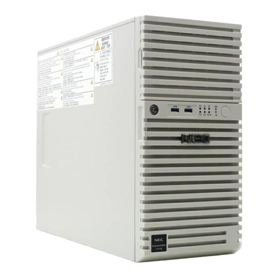
Chapter 1 General Description 4. Names and Functions of Parts Names and Functions of Parts The names and the functions of the server's parts are as follows. Front of the Server POWER Switch Optical Disk Drive A switch for turning on/off the server. Press once to turn on An optical disk drive for reading a CD/DVD. -
Page 23: Rear View
Chapter 1 General Description 4. Names and Functions of Parts Rear View <Non-redundant power supply model> <Redundant power supply model> 11-1 11-2 10 9 10 9 AC Inlet LAN Connectors Sockets for connecting power cords. 7-1 LAN1 Connector PCI Slots 7-2 LAN2 Connector Slots for installing PCI cards. -
Page 24: Internal View
Chapter 1 General Description 4. Names and Functions of Parts Internal View <Non-redundant power supply model> The images below do not show the air duct. Power Supply Unit 5.25-inch Expansion Bay Cooling Fan (CPU) A bay to mount the backup device. DIMM Slots Motherboard Hard Disk Drive Bay... - Page 25 Chapter 1 General Description 4. Names and Functions of Parts <Redundant power supply model> The images below do not show the air duct. Power Supply Unit 5.25-inch Expansion Bay Cooling Fan (CPU) A bay to mount the backup device. DIMM Slots Motherboard Hard Disk Drive Bay PCI Slot...
-
Page 26: Motherboard
Chapter 1 General Description 4. Names and Functions of Parts Motherboard 26 27 28 1-(2) 1-(4) 1-(1) 1-(3) 17-(1) 17-(2) 17-(3) 17-(4) 14 24 DIMM Slots (the number after hyphen indicates DIMM PCI Card Slots number) 17-(1) PCI EXPRESS x4 (x8 connector) 17-(2) PCI EXPRESS x4 (x8 connector) Power Connector 17-(3) PCI EXPRESS x16 (x16 connector) -
Page 27: Indicators
The next table lists STATUS LED patterns, their description and action. If the LED indication does not change even if the action below is performed, contact your sales representative. Tips Refer to the system event log (SEL) by using NEC ESMPRO or the offline maintenance utility to view the cause of failure. Express5800/T110j User’s Guide... - Page 28 (one of the features of BMC Management Console). SEL area becomes full (1024 records) Clear the SEL by Server Configuration Utility, BMC Management Console or NEC ESMPRO Manager. Blinking (amber) Power Supply Unit is failing (in power Contact your sales representative.
-
Page 29: Global Hdd Led 1, 2 (1- -2 )
Chapter 1 General Description 4. Names and Functions of Parts 4.5.3 Global HDD LED 1, 2 (1- -2 ) Global HDD LED indicates the status of the internal hard disk drive or optical disk drive. Global HDD1, 2 LED pattern Configuration Description Global HDD LED 1... -
Page 30: Led On A Hard Disk Drive
Chapter 1 General Description 4. Names and Functions of Parts 4.5.6 LED on a hard disk drive If 3.5-inch or 2.5-inch Hot Plug Drive Cage Kit is installed, each drive has its respective LED (Disk LED). DISK LED 1 (green) DISK LED 2 (amber) DISK LED 2 (amber) DISK LED 1 (green) -
Page 31: Link/Act Led ( 1, 2, M)
Chapter 1 General Description 4. Names and Functions of Parts 4.5.7 LINK/ACT LED ( This LED indicates the status of the LAN port. LINK/ACT LED pattern Description On (green) The server is correctly connected with network. Blinking (green) The server is accessing network. The server is disconnected from network. -
Page 32: Chapter 2 Preparations
NEC Express5800 Series Express5800/T110j Preparations This chapter describes preparations for using this server. 1. Installing Internal Optional Devices Describes how to install or remove optional devices. You can skip this section if you did not purchase any optional devices. 2. Installation and Connection Place the server in a proper location and connect some cables following this section. -
Page 33: Installing Internal Optional Devices
Chapter 2 Preparations 1. Installing Internal Optional Devices Installing Internal Optional Devices This chapter describes the instructions for installing supported optional devices and precautions. If you did not purchase any optional device requiring installation, you can skip this section. Important If you use the third party optional device to the server, and it causes failure, a charge for repairing must be paid even within the warranty period. -
Page 34: Overview Of Installation And Removal
Chapter 2 Preparations 1. Installing Internal Optional Devices Overview of Installation and Removal Install/remove components by using the following procedure. Turn the server off. See Chapter 3 (6. Turning off the Server). Disconnect all the power cables connected to the server from the outlet, and then disconnect them from the server. -
Page 35: Removing The Side Cover
Chapter 2 Preparations 1. Installing Internal Optional Devices Removing the Side Cover Remove the side cover by using the following procedure. See steps 1 to 3 in Chapter 2 (1.2 Overview of Installation and Removal) for preparations. Unlock the chassis, if necessary. Remove the two screws on the rear panel. -
Page 36: Removing The Front Bezel
Chapter 2 Preparations 1. Installing Internal Optional Devices Removing the Front Bezel Remove the front bezel by using the following procedure. See steps 1 to 3 in Chapter 2 (1.2 Overview of Installation and Removal) for preparations. Using the indentation on the left side of the front bezel, pull the front bezel forward until the tab pops out of the frame. -
Page 37: Tpm Kit
Chapter 2 Preparations 1. Installing Internal Optional Devices TPM Kit This section describes the procedure for installing optional TPM Kit. TPM kit connector Installation Install the TPM Kit in accordance with the following procedure. Note The TPM kit once installed cannot be removed. See steps 1 to 5 in Chapter 2 (1.2 Overview of Installation and Removal) for preparations. -
Page 38: Dimm
Up to 64 GB (16GB 4) of memory can be installed. Important Use only the DIMMs specified by NEC. Avoid static electricity to work with the procedure below. For details, see Chapter 1 (1.8 Anti-static measures) in Safety Precautions and Regulatory Notices. -
Page 39: Maximum Supported Memory Size
Chapter 2 Preparations 1. Installing Internal Optional Devices Maximum supported memory size The maximum available memory size on the server depends on the architecture (x86 architecture) and OS specs. A list of maximum memory sizes The maximum memory size The maximum memory size supported on each OS supported on the server Windows Server 2019 Standard... -
Page 40: Installation
Chapter 2 Preparations 1. Installing Internal Optional Devices Installation Install a DIMM by using the following procedure. See steps 1 to 4 in Chapter 2 (1.2 Overview of Installation and Removal) for preparations. Hold the server with both hands and slowly and gently lay it so that the left side faces upward. Open both levers of the target DIMM slot outward. -
Page 41: Removal
When removing a defective DIMM, check error messages displayed at POST or NEC ESMPRO and check the DIMM slot where the defective DIMM is installed. At least one DIMM needs to be installed for the server to operate. -
Page 42: Use Of Internal Hard Disk Drives In The Raid System
Chapter 2 Preparations 1. Installing Internal Optional Devices Use of Internal Hard Disk Drives in the RAID System This section describes how to use the hard disk drives installed in the HDD cage at the front of the server in the RAID system. - Page 43 Chapter 2 Preparations 1. Installing Internal Optional Devices Using an optional RAID controller Note When installing an optional RAID controller, start the BIOS Setup utility, select PCI Configuration from the Advanced menu, and then make sure that the parameter of PCI Slot xx ROM (xx is PCI slot number) is set to Enabled. Important Do not change the mode to hibernate when building a RAID system.
-
Page 44: Notes On Setting Up A Raid System
Chapter 2 Preparations 1. Installing Internal Optional Devices Notes on setting up a RAID system Note the following points when setting up a RAID system. The number of hard disk drives required varies depending on the RAID level. If SW RAID controller or an optional RAID controller (N8103-205/206/210) is used, the RAID system cannot be built in RAID5/RAID6/RAID50/RAID60. - Page 45 Chapter 2 Preparations 1. Installing Internal Optional Devices <3.5-inch fixed HDD cage installed> <3.5-inch HDD cage installed> N8154-81F N8154-79F 3.5-inch fixed HDD cage 3.5-inch HDD cage < 2.5-inch HDD cage installed> N8154-80F 2.5-inch HDD cage 1 2 3 4 5 6 7 Express5800/T110j User’s Guide...
-
Page 46: Flash Backup Unit For Raid Controller
Chapter 2 Preparations 1. Installing Internal Optional Devices Flash Backup Unit for RAID Controller The optional flash backup unit is used in order to avoid data loss caused by accidents during a write-back operation. N8103-209 flash backup unit Handling precautions Observe the following precautions to use the flash backup unit. - Page 47 Chapter 2 Preparations 1. Installing Internal Optional Devices Connecting the flash backup unit control cable To connect the flash backup unit control cable into the battery pack, see the following figure. Check the form of the connector and connect the cable straight into the connector. Getting ready to install the battery...
-
Page 48: Removal
Chapter 2 Preparations 1. Installing Internal Optional Devices Position of the connector Connect the cable to the connector shown in the figure below. Tips For the position of the connector of N8103-206/207/208, refer to the manual attached to N8103-206/207/208. flash backup unit control cable RAID Controller Install the RAID controller into the PCI slot #4 and fix it in place. -
Page 49: Pci Card
Chapter 2 Preparations 1. Installing Internal Optional Devices PCI Card This server provides four slots where PCI cards can be installed. Important Avoid static electricity to work with the procedure below. For details, see Chapter 1 (1.8 Anti-static measures)) in Safety Precautions and Regulatory Notices. -
Page 50: Notes
Chapter 2 Preparations 1. Installing Internal Optional Devices Notes Read the following notes when installing or removing a PCI card. Do not touch the terminals of cards and the leads of electronic components with your bare hand. Fingerprints and dust left on them cause the server to malfunction due to a connection failure or damage to the leads. -
Page 51: List Of Optional Devices And Installation Slots
Chapter 2 Preparations 1. Installing Internal Optional Devices List of optional devices and installation slots PCI Express3.0 PCI#1 PCI#2 PCI#3 PCI#4 PCI slot performance lane lane lane lane Model name Product name Remark PCI slot size Full Height PCI board socket type Size of mountable 168 mm 168 mm... - Page 52 Chapter 2 Preparations 1. Installing Internal Optional Devices About the standard network You can use functional equivalents of AFT/SFT/ALB teaming and bonding with the standard network and the following LAN cards: N8104-150, N8104-151, and N8104-152 PCI slot limitations See the table below for the limitations on installing PCI cards (due to the number of interrupts that can be processed in the system) depending on the installed processor.
-
Page 53: Installation
Chapter 2 Preparations 1. Installing Internal Optional Devices Installation Install a PCI card to connect to a PCI slot by using the following procedure. Before installation, make sure the switch or jumper settings on the PCI card are proper according to the instruction manual supplied with the card. - Page 54 Chapter 2 Preparations 1. Installing Internal Optional Devices Face the component side of the card toward the bottom of the server. Make sure PCI bracket is aligned and sit appropriate within frame guide. When the rear panel of the card is firmly engaged with the spring, firmly press the card into the slot so that the component parts of the card securely connect to the slot.
-
Page 55: Configuration After Installing
Chapter 2 Preparations 1. Installing Internal Optional Devices Configuration after installing Depending on the type of card installed, you need to use a utility, such as the BIOS setup utility, a setup utility provided with the card, following installation to modify server settings. Follow the instructions in the manual provided with the card to specify the correct settings. -
Page 56: Installing The N8117-01A Extra Rs-232C Connector Kit
Chapter 2 Preparations 1. Installing Internal Optional Devices Installing the N8117-01A extra RS-232C connector kit Install a PCI card to connect to the PCI slot by using the following procedure. For details, refer to the instruction manual supplied with the connector kit. The component parts for N8117-01A are as follows: Item no. - Page 57 Chapter 2 Preparations 1. Installing Internal Optional Devices Make sure that you are properly inserting the bracket edge into the frame guide, and attach it securely. Arrange the cable so as not to buffer other PCI cards, and connect to the COM connector used for internal connections in the motherboard.
-
Page 58: Power Supply Fan
Chapter 2 Preparations 1. Installing Internal Optional Devices 1.10 Power Supply Fan In the following configuration of the non-redundant power source, the optional power supply support fan is required. When mounting the optional RAID controller When mounting the optional dustproof bezel ... -
Page 59: Removal
Chapter 2 Preparations 1. Installing Internal Optional Devices Connect the cable of the Power Supply Fan to the connector (FAN3) on the motherboard. Update the system configuration information by following procedure. 1) Connect the AC cord to the server, then push the power switch to power on. 2) If POST screen is indicated, press F2 key of the keyboard and enter BIOS setup screen. -
Page 60: Hdd Cages And Hard Disk Drives
N8154-81F 3.5-inch fixed HDD cage, N8154-79F 3.5-inch HDD cage, or N8154-80F 2.5-inch HDD cage can be installed in the HDD bay in this server. Important Use hard disk drives provided by NEC. <3.5-inch fixed HDD cage installed> <3.5-inch HDD cage installed>... -
Page 61: Installing A 3.5-Inch Fixed Hdd Cage And Hard Disk Drives
Installing a 3.5-inch fixed HDD cage and hard disk drives By installing a 3.5-inch fixed HDD cage, up to four 3.5-inch SATA fixed hard disk drives can be mounted. Important Use hard disk drives provided by NEC. Important Install the hard disk drives sequentially starting from slot 0. - Page 62 Chapter 2 Preparations 1. Installing Internal Optional Devices Install a 3.5-inch fixed HDD cage and hard disk drives in the server by using the following procedure. See steps 1 to 3 in Chapter 2 (1.2 Overview of Installation and Removal) for preparations. To remove the side cover and front bezel, see Chapter 2 (1.3 Removing the Side Cover and 1.4 Removing the Front Bezel).
-
Page 63: Removing The 3.5-Inch Fixed Hard Disk Drives
Chapter 2 Preparations 1. Installing Internal Optional Devices Update the system configuration information by following procedure. 1) Connect the AC cord to the server, then push the power switch to power on. 2) If POST screen is indicated, press F2 key of the keyboard and enter BIOS setup screen. 3) The POWER switch is pressed and the power supply of the server is turned off. -
Page 64: Removing The 3.5-Inch Fixed Hdd Cage
Chapter 2 Preparations 1. Installing Internal Optional Devices Removing the 3.5-inch fixed HDD cage Remove the 3.5-inch fixed HDD cage from the server by using the following procedure. See steps 1 to 3 in Chapter 2 (1.2 Overview of Installation and Removal) for preparations. To remove the side cover and front bezel, see Chapter 2 (1.3 Removing the Side Cover and 1.4 Removing the Front Bezel). -
Page 65: Installing The 3.5-Inch Hdd Cage And Hard Disk Drives
Installing the 3.5-inch HDD cage and hard disk drives By installing a 3.5-inch HDD cage, up to four 3.5-inch SATA fixed hard disk drives can be mounted. Important Use hard disk drives provided by NEC. Important Install the hard disk drives sequentially starting from slot 0. - Page 66 Chapter 2 Preparations 1. Installing Internal Optional Devices Install a 3.5-inch HDD cage and hard disk drives in the server by using the following procedure. See steps 1 to 3 in Chapter 2 (1.2 Overview of Installation and Removal) for preparations. To remove the side cover and front bezel, see Chapter 2 (1.3 Removing the Side Cover and 1.4 Removing the Front Bezel).
- Page 67 Chapter 2 Preparations 1. Installing Internal Optional Devices Unlock the handle in the tray for a hard disk drive. Hold the tray firmly and insert it in the slot. Note Push it all the way until the handle’s lock touches the frame. Hold the drive carrier firmly with both hands.
-
Page 68: Removing The 3.5-Inch Hard Disk Drives
Chapter 2 Preparations 1. Installing Internal Optional Devices Update the system configuration information by following procedure. 1) Connect the AC cord to the server, then push the power switch to power on. 2) If POST screen is indicated, press F2 key of the keyboard and enter BIOS setup screen. 3) The POWER switch is pressed and the power supply of the server is turned off. - Page 69 Chapter 2 Preparations 1. Installing Internal Optional Devices Hold the tray firmly and pull it toward the front. Note Do not pull the handle to remove the hard disk drive. Doing so may damage the handle. Important Do not use this server while removing the hard disk drive. Express5800/T110j User’s Guide...
-
Page 70: Removing The 3.5-Inch Hdd Cage
Chapter 2 Preparations 1. Installing Internal Optional Devices Removing the 3.5-inch HDD cage Remove the 3.5-inch HDD cage from the server by using the following procedure. See steps 1 to 3 in Chapter 2 (1.2 Overview of Installation and Removal) for preparations. To remove the side cover and front bezel, see Chapter 2 (1.3 Removing the Side Cover and 1.4 Removing the Front Bezel). -
Page 71: Installing The 2.5-Inch Hdd Cage And Hard Disk Drives
Mount SATA/SAS hard disk drives in order from slot 0, and mount the SSDs to the remaining slots. Important Use hard disk drives provided by NEC. 1 2 3 4 5 6 7 Important Install the hard disk drives sequentially starting from slot 0. - Page 72 Chapter 2 Preparations 1. Installing Internal Optional Devices Install a 2.5-inch HDD cage and hard disk drives in the server by using the following procedure. See steps 1 to 3 in Chapter 2 (1.2 Overview of Installation and Removal) for preparations. To remove the side cover and front bezel, see Chapter 2 (1.3 Removing the Side Cover and 1.4 Removing the Front Bezel).
- Page 73 Chapter 2 Preparations 1. Installing Internal Optional Devices Unlock the handle in the tray for a hard disk drive. Hold the tray firmly and insert it in the slot. Note Push it all the way until the handle’s lock touches the frame. ...
-
Page 74: Removing The 2.5-Inch Hard Disk Drives
Chapter 2 Preparations 1. Installing Internal Optional Devices Removing the 2.5-inch hard disk drives Remove the 2.5-inch hard disk drives from the HDD cage by using the following procedure. Important When disposing of the hard disk drives, follow the instructions described in Chapter 1 (1.5 Transfer, movement, and disposal) in Safety Precautions and Regulatory Notices. -
Page 75: Removing The 2.5-Inch Hdd Cage
Chapter 2 Preparations 1. Installing Internal Optional Devices Removing the 2.5-inch HDD cage Remove the 2.5-inch HDD cage from the server by using the following procedure. See steps 1 to 3 in Chapter 2 (1.2 Overview of Installation and Removal) for preparations. To remove the side cover and front bezel, see Chapter 2 (1.3 Removing the Side Cover and 1.4 Removing the Front Bezel). -
Page 76: Optical Disk Drive
Chapter 2 Preparations 1. Installing Internal Optional Devices 1.12 Optical Disk Drive Procedures for replacing the standard optical disk drive with the optional internal DVD SuperMULTI drive are described below. Important Do not install a drive manufactured by a third party. Replacing drives Follow the procedure below to replace your drive with the optional internal DVD SuperMULTI drive. -
Page 77: Backup Devices
Chapter 2 Preparations 1. Installing Internal Optional Devices 1.13 Backup Devices The 5.25-inch expansion bay of the server can contain a backup device such as a magnetic tape drive. 5.25-inch expansion bay 2 5.25-inch expansion bay 1 Installation Install a backup device by using the following procedure. See Chapter 2 (1.2 Overview of Installation and Removal) for preparations. -
Page 78: Removal
Chapter 2 Preparations 1. Installing Internal Optional Devices Insert the backup device into chassis. Do not push the backup device in completely as the cable has to be connected to the device. Connect the interface cable and power cable to the installed 3.5-inch backup device. For more information, see Chapter 2 (1.16 Connecting Cables). -
Page 79: Supporting High-Temperature Environment
Chapter 2 Preparations 1. Installing Internal Optional Devices 1.14 Supporting High-temperature Environment The high-temperature environment setting of this server enables you to use this server under the environment of 5°C to 48°C. For the high-temperature environment setting, the following configuration is required. •... -
Page 80: Vmware Esxi Base Kit (N8106-018)
Chapter 2 Preparations 1. Installing Internal Optional Devices 1.15 VMware ESXi Base kit (N8106-018) This section describes the procedure for installing optional VMware ESXi Base kit. Serial ATA connector (for VMware ESXi) Installation Install the VMware ESXi Base kit in accordance with the following procedure. See steps 1 to 4 in Chapter 2 (1.2 Overview of Installation and Removal) for preparations. -
Page 81: Connecting Cables
Chapter 2 Preparations 1. Installing Internal Optional Devices 1.16 Connecting Cables This section shows an example of internal device cable connection. Internal interface cables This section describes the connection of internal interface cables. Tips The figure shown here primarily describes connections. For more information about the connectors on the motherboard, see Chapter 1 (4.4 Motherboard). - Page 82 Chapter 2 Preparations 1. Installing Internal Optional Devices Adding a RAID controller (N8103-205/206/207/208/210/211) Power supply Motherboard HDD cage HDD_LED1 Flash Backup Unit RAID controller miniSAS cable Flash back up unit control cable (only when the RAID controller is N8103-206/207/208) LED cable * N8103-209 cannot be installed to N8103-205/210/211.
- Page 83 Chapter 2 Preparations 1. Installing Internal Optional Devices About RAID LED cables The Global HDD LED on the front of the equipment shows the access status of hard disk drives that are connected to a RAID controller. To display this status, connect the LED cable that comes with the optional cable K410-444(00).
- Page 84 Chapter 2 Preparations 1. Installing Internal Optional Devices Using 3.5-inch HDD cage Connect the cables as shown in the following figure. Install the hard disk drives in order from the left side. Connecting to the miniSAS connector on the motherboard Power supply Motherboard...
- Page 85 Chapter 2 Preparations 1. Installing Internal Optional Devices Using 2.5-inch HDD cage Connect the cables as shown in the following figure. Install the hard disk drives in order from the left side. Connecting one to four hard disk drives to the miniSAS connector on the motherboard Power supply MINISAS_1...
- Page 86 Chapter 2 Preparations 1. Installing Internal Optional Devices (2) Connecting backup devices The 5.25-inch expansion bay of the server can mount USB devices for internal connection. Mounting an internal USB device Use the dedicated internal USB cable (K410-276(00)). Power supply Backup devices Optical disk drive Motherboard...
- Page 87 Chapter 2 Preparations 1. Installing Internal Optional Devices (3) Connecting Dual M.2 SATA mount kit (N8118-307) The server can mount dual M.2 SATA mount kit (N811-307) which mounted at most 2 of 120GB M.2 SATA SSD (N8150-736) or 240GB M.2 SATA SSD (N8150-1732) for internal connection. (In case of 2 set M.2 SSD installed, both M.2 SSD should be same capacity.) When SSD is used in software RAID Use the dedicated internal SAS/SATA cable (K410-365(00)) and connecting to the miniSAS connector on...
- Page 88 Chapter 2 Preparations 1. Installing Internal Optional Devices When SSD is used in hardware RAID Use the dedicated internal SAS/SATA cable (K410-365(00)) and connecting to the RAID controller. RAID LED cable (K410-444(00)): When using the RAID controller (N8103-205/206/210) Note M.2 SATA SSD and hard disc drive cannot be connected to the same RAID controller.
-
Page 89: Power Cables
1. Installing Internal Optional Devices Power cables The figure below shows an example of connecting the power cables. Power cables other than those shown here are not used by the devices. (1) Non-Redundant Power Supply Model (EXP339) Using 3.5-inch fixed HDD cage Power supply... - Page 90 Chapter 2 Preparations 1. Installing Internal Optional Devices Using 2.5-inch HDD cage P12 P15 Power supply Backup devices Optical disk drive PWR_DET1 HDD cage Power convert cable Motherboard Cable connected to power supply Unused power supply cable connector (2) Redundant Power Supply Model (EXP339A) Using 3.5-inch fixed HDD cage Power supply...
- Page 91 Chapter 2 Preparations 1. Installing Internal Optional Devices Using 3.5-inch HDD cage Power supply 5.2Dev2 Backup devices 5.2Dev1 Optical disk drive HDDBP1 PWR_DET1 HDDBP2 HDD cage Motherboard Cable connected to power supply backplane DC cable Unused power supply cable connector Using 2.5-inch HDD cage Power supply...
-
Page 92: Attaching The Front Bezel
Chapter 2 Preparations 1. Installing Internal Optional Devices 1.17 Attaching the Front Bezel You can attach the front bezel by reversing the removal procedure. Attach the front bezel to the server by inserting the three tabs on the inside of the front bezel into the slits on the right-front of the server and then pressing the left side of the front bezel to secure it into place on the front of the server. -
Page 93: Installing The Side Cover
Chapter 2 Preparations 1. Installing Internal Optional Devices 1.18 Installing the Side Cover You can attach the side cover by reversing the removal procedure. Make sure that hooks at both the top and bottom of the side cover are securely inserted in the slits on the server frame. -
Page 94: Installation And Connection
Chapter 2 Preparations 2. Installation and Connection Installation and Connection This section describes how to position the server and connect cables. Installation W ARNING Be sure to observe the following precautions to use the server safety. Failure to observe the precautions may cause death or serious injury. For details, refer to Safety Precautions and Regulatory Notices. - Page 95 Chapter 2 Preparations 2. Installation and Connection Do not install the server in an environment in which any of the following conditions apply: Installing the server in any of the following conditions will cause the server to malfunction. Places where corrosive gas is present, such as environments where there is sulfur vapor in the atmosphere, or Place of drastic temperature change,...
-
Page 96: Preparation For Installation
Chapter 2 Preparations 2. Installation and Connection Preparation for installation Remove the stabilizer attached to the bottom of the server, and then change as instructed below. Removing/installing the stabilizer Removing the stabilizer Remove the two screws from the stabilizer to remove the stabilizer from the server. Installing the stabilizer Turn the stabilizer 90 degree as shown in the figure below, and then fix it by using the two screws. -
Page 97: Connection
Chapter 2 Preparations 2. Installation and Connection Connection Connect peripheral devices to the server. Connectors that enable a variety of peripheral devices to be connected are provided at the front and rear of the server. Figures on the following pages show the peripheral devices that can be connected as standard. -
Page 98: Interface Cables
Chapter 2 Preparations 2. Installation and Connection Interface cables Connect the interface cable before connecting the power cord. Important Turn off the server and peripheral devices to be connected before connecting. If you use the third party display or peripheral devices, and connect the interface cable, contact the dealer to check whether they can be used. -
Page 99: Power Cord
Chapter 2 Preparations 2. Installation and Connection Power cord Connect the provided power cord to the server. Non-Redundant Power Supply Model (EXP339) Note Appearance of the power supply unit varies depending on the model number. Redundant Power Supply Model (EXP339A) When the power cord is connected to an outlet, POWER LED lights amber during initialization of the system. - Page 100 Chapter 2 Preparations 2. Installation and Connection Installation of AC cable tie Important Install AC cable tie attached to the server on the power supply and fix power code with it. It is necessary to keep cooling efficiency for inside of the server and prevent AC power cord pulling off by accident..
-
Page 101: Chapter 3 Setup
NEC Express5800 Series Express5800/T110j Setup This chapter describes how to set up the server. 1. Turning on the Server Power-On Self-Test (POST) is explained in this section. 2. System BIOS Setup You can customize BIOS settings by following the instructions in this section. -
Page 102: Turning On The Server
Power Supply (UPS), make sure that the power control system is turned on. 3. If STATUS LED1,2 lights green/amber, wait until STATUS LED is unlit. 4. Press POWER Switch at the front of the server. POWER LED is turned on green and after a while, NEC logo appears on the display. POWER While the logo is being displayed, the self-diagnostic program (POST) runs and diagnoses the hardware. -
Page 103: Post
In such a case, press F1 to continue POST. Board configuration can be made using the utility described later. 1. POST runs automatically when the server is turned on. NEC logo appears on the screen as factory settings. Note Keyboard becomes operable after the logo appears. -
Page 104: Post Error Messages
Chapter 3 Setup 1. Turning on the Server 4. After a while, the following message is displayed on the screen. Press <F2> to enter setup, <F3> Internal Flash Memory, <F10> Display Boot Menu , <F12> Force Network Boot You can call the functions below upon completion of POST by pressing the designated function key. <F2>... -
Page 105: System Bios Setup
Press <F2> to enter setup, <F3> Internal Flash Memory, <F10> Display Boot Menu , <F12> Force Network Boot When you press <F2> key during displaying the message or the NEC logo, SETUP runs and displays the Main menu upon completion of POST. -
Page 106: Description On On-Screen Items And Key Usage
Chapter 3 Setup 2. System BIOS Setup Description on On-Screen Items and Key Usage This section explains how to use SETUP. Use the keyboard to work with SETUP. Indicates the currently displayed menu Items Help Indicates the menu has submenus. Parameters (highlighted when selected*) *: Items that cannot be specified are gray-out. - Page 107 Chapter 3 Setup 2. System BIOS Setup <F3> key Press this key to restore the parameters. If you choose Yes in the following message, the previous parameter(s) are restored. Load Previous Values? [Yes] <F9> key Press this key to load default settings. If you choose Yes in the following message, the default settings of SETUP are restored.
-
Page 108: Cases That Require Setting Changes
On/Off NumLock on power ON Boot Bootup Numlock State Boot Quite Boot Disabled On/Off the function to display By pressing <Esc> key, the NEC logo during POST prevent the display of the logo. Advanced PCI Subsystem PCI Optional... - Page 109 Chapter 3 Setup 2. System BIOS Setup Category Description To be changed Remark Security Administrator Password Security Set a password to restrict After a password is set, the Security User password operation of SETUP. entry of password is displayed when SETUP is launched.
-
Page 110: Bmc Management Console
Chapter 3 Setup 3. BMC Management Console BMC Management Console Overview BMC Management Console provides a variety of features using BMC (Baseboard Management Controller), which is a system management LSI. See BMC Management Console User's Guide for detailed information. BMC monitors the power supply unit, fans, temperature, and voltage of the server. If you have the management LAN port connected to the network, you can remotely perform the following over a web browser: ... - Page 111 Chapter 3 Setup 3. BMC Management Console Select [Server Mgmt]-[BMC network configuration]. On the following screen, select [DynamicBmcDhcp] in Configuration Address source when you use DHCP, or configure items below Station IP address. Tips If Shared BMC LAN is enabled, Web feature, remote media/KVM feature, or command line interface feature may be interrupted.
- Page 112 Chapter 3 Setup 3. BMC Management Console Connect the LAN cable to the management LAN connector in order to connect to the network. It will be available for use if you access BMC Web Console via Web browser from management PC according to the setting.
-
Page 113: Expressbuilder
Ensure a CD/DVD is removed from the server, turn on the server, and then press <F3> key during POST. Windows Application: You can run EXPRESSBUILDER by clicking the shortcut of NEC EXPRESSBUILDER on the desktop, or select NEC EXPRESSBUILDER from Windows Start menu or Start screen after installing Windows and Starter Pack. -
Page 114: Installing Software Components
Chapter 3 Setup 5. Installing Software Components Installing Software Components Continue to install the operating system and other bundled software. See the instructions below. Installation Guide (Windows) Express5800/T110j User’s Guide... -
Page 115: Turning Off The Server
Chapter 3 Setup 6. Turning off the Server Turning off the Server Turn off the server by using the following procedure. When the power cord of the server is connected to a UPS, refer to the documentation supplied with the UPS or the documentation for the application controlling the UPS. 1. - Page 116 NEC Express5800 Series Express5800/T110j Appendix 1. Specifications Describes specifications of the server. 2. Interrupt Lines Describes the interrupt lines assigned to this server. 3. Glossary Describes glossaries of this document. 4. Revision Record Describes revision history of this document. Express5800/T110j User’s Guide...
-
Page 117: Chapter 4 Appendix
Chapter 4 Appendix 1. Specifications Specifications Express5800/T110j (EXP339) Express5800/T110j (EXP339) Product name N8100-2765F Type Intel Celeron Intel Pentium Intel Core-i3 processor G4900 processor G5400 processor 8300 Clock/cache 3.1 GHz/2 MB 3.7 GHz/4 MB 3.7 GHz/8 MB Standard / (maximum) Not pre-installed / (1) - Page 118 Chapter 4 Appendix 1. Specifications Express5800/T110j (EXP339) Product name N8100-2765F Type Intel Xeon Intel Xeon Intel Xeon Intel Xeon processor processor processor processor E-2124 E-2124G E-2126G E-2134 Clock/cache 3.3 GHz/8 MB 3.4 GHz/8 MB 3.3 GHz/12 MB 3.5 GHz/8 MB...
- Page 119 Chapter 4 Appendix 1. Specifications Express5800/T110j (EXP339) Product name N8100-2765F Type Intel Xeon Intel Xeon processor processor E-2146G E-2174G Clock/cache 3.5 GHz/12 MB 3.8 GHz/8 MB Standard / Not pre-installed / (1) (maximum) Chipset Intel C246 Chipset Memory Standard Not pre-installed...
-
Page 120: Express5800/T110J (Exp339A)
Chapter 4 Appendix 1. Specifications Express5800/T110j (EXP339A) Express5800/T110j (EXP339A) Product name N8100-2764F Type Intel Celeron Intel Pentium Intel Core-i3 processor G4900 processor G5400 processor 8300 Clock/cache 3.1 GHz/2 MB 3.7 GHz/4 MB 3.7 GHz/8 MB Standard / Not pre-installed / (1) (maximum) Chipset Intel C246 Chipset... - Page 121 Chapter 4 Appendix 1. Specifications Express5800/T110j (EXP339A) Product name N8100-2764F Type Intel Xeon Intel Xeon Intel Xeon Intel Xeon processor processor processor processor E-2124 E-2124G E-2126G E-2134 Clock/cache 3.3 GHz/8 MB 3.4 GHz/8 MB 3.3 GHz/12 MB 3.5 GHz/8 MB Standard / Not pre-installed / (1) (maximum)
- Page 122 Chapter 4 Appendix 1. Specifications Express5800/T110j (EXP339A) Product name N8100-2764F Type Intel Xeon Intel Xeon processor processor E-2146G E-2174G Clock/cache 3.5 GHz/12 MB 3.8 GHz/8 MB Standard / Not pre-installed / (1) (maximum) Chipset Intel C246 Chipset Memory Standard Not pre-installed Maximum 64 GB (16 GB x 4) Expansion unit...
-
Page 123: Interrupt Lines
Chapter 4 Appendix 2. Interrupt Lines Interrupt Lines Interrupt lines are assigned as factory settings as shown below. Use this table as a reference when you add optional devices. Interrupt lines As factory settings, interrupt lines are assigned as follows. Peripheral Device (Controller) Peripheral Device (Controller) System timer... -
Page 124: Glossary
NEC ESMPRO Manager Software for managing multiple servers on network. NEC ESMPRO Software for monitoring the server. This works with NEC ESMPRO Manager. You can ServerAgentService choose Service Mode or Non-Service Mode when installing this software. Service Mode resides as the OS service and Non-Service Mode does not use the OS service to reduce memory, CPU power, and other OS resources. - Page 125 Software for setting RAID arrays on Windows/Linux. This software is operated on "PC Universal RAID Utility for Management" with NEC ESMPRO Manager. Windows OS parameter file A file that saved settings for installing Windows. You can install with the settings in this file when setting Windows with EXPRESSBUILDER.
-
Page 126: Revision Record
Chapter 4 Appendix 4. Revision Record Revision Record Revision (Document Number) Date Issued Description 10.118.02 101.01 December 2018 Newly created 10.118.02 101.02 December 2018 Overall revision 10.118.02 101.03 May 2019 Added WS2019 support Express5800/T110j User’s Guide... - Page 127 [MEMO]...
- Page 128 NEC Express Server Express5800/T110j User’s Guide May 2019 NEC Corporation 7-1 Shiba 5-Chome, Minato-Ku Tokyo 108-8001, Japan ©NEC Corporation 2019 The contents of this manual may not be copied or altered without the prior written permission of NEC Corporation.