Table of Contents
Advertisement
Quick Links
Advertisement
Table of Contents

Summary of Contents for Sharp MX-TMX1
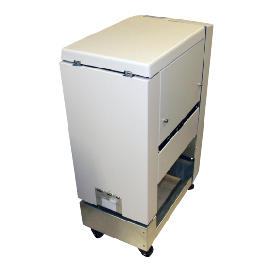
- Page 1 TRIMMER MX-TMX1 SERVICE MANUAL 20 October 2010 Subject to change...
- Page 2 Page intentionally blank...
-
Page 3: Table Of Contents
20 October 2010 TABLE OF CONTENTS 1 INSTALLATION PROCEDURE 1.1 INSTALLATION PROCEDURE ............TR-1-1 2 PREVENTIVE MAINTENANCE SCHEDULE 2.1 PREVENTIVE MAINTENANCE SCHEDULE ........TR-2-1 3. REPLACEMENT AND ADJUSTMENT 3.1 COVERS ..................... TR-3-1 3.1.1 FRONT AND REAR COVER ............. TR-3-1 3.1.2 TOP COVER ................TR-3-2 3.1.3 BLOWER MOTOR M5 / M6 ............ - Page 4 20 October 2010 6. DETAILED SECTION DESCRIPTIONS 6.1 ELECTRICAL COMPONENT LIST ............. TR-6-1 6.1.1 REAR VIEW ................TR-6-2 6.1.2 INFEED VIEW ................TR-6-3 6.1.3 OUTFEED VIEW ............... TR-6-4 6.1.4 STOP CARRIAGE VIEW ............TR-6-5 6.2 BOARD STRUCTURE ................ TR-6-7 6.2.1 BLOCK DIAGRAM ..............TR-6-7 6.2.2 CONTROLLER MD6DC ............
-
Page 5: Installation Procedure
20 October 2010 INSTALLATION PROCEDURE INSTALLATION PROCEDURE Trimmer INSTALLATION PROCEDURE is located in the Booklet Maker MX-BMX1 Service Manual ( 1.5) TR-1-1... - Page 6 Page intentionally blank...
-
Page 7: Preventive Maintenance Schedule
20 October 2010 PREVENTIVE MAINTENANCE SCHEDULE PREVENTIVE MAINTENANCE SCHEDULE Trimmer PREVENTIVE MAINTENANCE SCHEDULE is located in the Booklet Maker MX-BMX1 Service Manual ( TR-2-1... - Page 8 Page intentionally blank...
-
Page 9: Replacement And Adjustment
20 October 2010 COVERS REPLACEMENT AND ADJUSTMENT COVERS 3.1.1 FRONT AND REAR COVER Front Cover Open the Top Cover. Remove screws [A] ( Loosen screws [B] ( Rear Cover Loosen screws [C] ( TR-3-1... -
Page 10: Top Cover
COVERS 20 October 2010 3.1.2 TOP COVER Good Top cover too low Top cover too high Removal Pry off the Gas spring [A] using a screw driver. Remove screws and nuts [B] ( x4). Replacement Reverse the removal procedure. Adjustment Loosen screws and nuts [B] ( x4). -
Page 11: Blower Motor M5 / M6
20 October 2010 COVERS 3.1.3 BLOWER MOTOR M5 / M6 Removal Open the Top Cover. Cut tie-wrap [A] Disconnect connectors [B] ( x2). Remove Front and Rear cover ( 3.1.1). Remove Infeed cover ( 3.1.4). Remove screws [C] ( x2). Lift out Fan assy Replacement Reverse the removal procedure. -
Page 12: Infeed Cover
COVERS 20 October 2010 3.1.4 INFEED COVER Open the Top Cover. Remove Front and Rear cover ( 3.1.1). Remove screws [A] ( x5). Remove screws [B] ( x5). TR-3-4... -
Page 13: Locking Bracket
20 October 2010 COVERS 3.1.5 LOCKING BRACKET Removal Loosen nuts [A] ( x2). Locking bracket will fall down. Replacement Push Trimmer against Bookletmaker. Push up Locking bracket so it latches studs [B]. Tighten nuts [A] ( x2). TR-3-5... -
Page 14: Upper Outfeed Cover
COVERS 20 October 2010 3.1.6 UPPER OUTFEED COVER Remove Belt stacker. Remove Front and Rear cover ( 3.1.1). Open the Top Cover. Remove the Gas spring [A] by prying it off using a screw driver. Remove connector [B] ( x1). Cut cable ties [C] inside cover. -
Page 15: Interlock Switch S9 &S10
Check adjustment according to ( 3.1.10). WARNING Overriding or cheating the interlock allows the MX-TMX1 system to operate with the top cover open which can result in personal injury. Never give the operator access to the cheater or show how ovverriding the interlock sys- tem is carried out. -
Page 16: Lower Outfeed Cover
COVERS 20 October 2010 3.1.8 LOWER OUTFEED COVER Remove Belt stacker ( 3.8.1). Remove Front and Rear cover ( 3.1.1). Remove Protection Cover ( 3.1.9). Loosen screws [A] ( x2). Remove screws [B] ( x4). TR-3-8... -
Page 17: Protection Cover
20 October 2010 COVERS 3.1.9 PROTECTION COVER Replacement Step 1. Replacement Step 2. Removal Lift out scrap paper bin [B]. Remove screws [A] ( x4). Replacement Place the front end of the cover up against the lower knife beam [C]. Push in cover so it hooks onto the screws [D]. -
Page 18: Interlock Mechanism
COVERS 20 October 2010 3.1.10 INTERLOCK MECHANISM Removal 1. Remove screws [A] ( x 2). 2. Remove interlock mechanism bracket [B]. Replacement 1. Reverse the removal procedure. Adjustment Make sure interlock box is mounted correctly ( 3.1.7). Loosen nuts [A] ( x2). -
Page 19: Area C
20 October 2010 AREA C AREA C 3.2.1 INFEED SENSOR Q13 Undock the Trimmer. Remove nuts [A] inside bracket holding the Sensor bracket ( x2). Remove connector from the Sensor ( x1). Remove sensor [B]. TR-3-11... -
Page 20: Control Switch S2
AREA C 20 October 2010 3.2.2 CONTROL SWITCH S2 Removal Remove Rear cover ( 3.1.1). Remove connectors [A] ( x2). Remove screws [B] ( x2 ). Replacement Reverse the removal procedure. Adjustment Lift the Infeed shaft. Make sure the Switch activates slightly before the shaft latches in upper posi- tion. -
Page 21: Control Switch S3
20 October 2010 AREA C 3.2.3 CONTROL SWITCH S3 Removal Remove Rear cover ( 3.1.1). Remove connector [B] ( X2). Remove screw [A] ( x2). Replacement Reverse the removal procedure. Adjustment Lift the compressing bracket. Make sure the Switch activates approximately 10 mm from where the com- pressing bracket latches in the upper position. -
Page 22: Transport Motor M1
AREA C 20 October 2010 3.2.4 TRANSPORT MOTOR M1 Remove Transmission chain ( 3.2.17). Remove Knife support chain ( 3.2.18). Remove connector [A] ( x1). Grab the inner sprocket to pull out the whole sprocket assembly [B]. Remove screws [C] holding the motor ( x3). -
Page 23: Transport Belt Sensor Q4
20 October 2010 AREA C 3.2.5 TRANSPORT BELT SENSOR Q4 Removal Remove Rear cover ( 3.1.1). Remove connector [A] ( x1). Remove nut and screw [B] ( x1). Remove bracket [C]. Squeeze the barbs of the sensor to remove. Replacement Reverse the removal procedure NOTE: When tightening nut/screw make sure there is a space between en- coder disc and sensor. -
Page 24: Trim Knife Motor M2
AREA C 20 October 2010 3.2.6 TRIM KNIFE MOTOR M2 WARNING Place the safety block [D] between lower knife and upper knife beam. When removing the chain nothing holds upper knife beam and knife in position. Removal Remove Rear cover ( 3.1.1). -
Page 25: Trim Knife Home Postiton Sensor Q5
20 October 2010 AREA C 3.2.7 TRIM KNIFE HOME POSTITON SENSOR Q5 Removal Remove Rear cover ( 3.1.1). Remove connector [A] ( x1). Squeze the barbs of the sensor to remove. NOTE: Gently pull bracket [B] to remove. WARNING Stay clear from upper knife. The knife edge may cause serious injuries. Replacement Reverse the removal procedure. -
Page 26: Trim Knife
AREA C 20 October 2010 3.2.8 TRIM KNIFE WARNING Stay clear from upper knife. The knife edge may cause serious injuries. Place the safety block [A] between lower knife and upper knife beam. Keep the safety block in that position as much time as possible throughout this procedure. - Page 27 20 October 2010 AREA C Replacement Upper knife Move transport protection from the old to the new knife. Clean and apply grease on guide bars [J] and side guides [K]. Fit upper knife onto guide bars [J]. Apply grease on the cup spring washers [F] closest to the knife. Mount screws [E] with nuts [G] ( x6).
- Page 28 AREA C 20 October 2010 7. Use a feeler gauge and check that the space [Q] between upper knife and the two red marked reference screws in the middle [P] is 0.50 mm. Note: Never touch the red painted reference screws [P]. Adjust the space if necessary with screws [O] ( x2).
- Page 29 20 October 2010 AREA C 10. Check that the knife protection plate is secured from moving outwards by the lock on the rear side [U]. 11. Bring the Upper knife down to the bottom position by turning crank [R] using a 13 mm wrench.
- Page 30 20 October 2010 15. Slowly and carefully without paper lower the upper knife by turning crank [R]. Check that the upper knife does not contact the lower knife. In that case, back up the upper knife and start over from step 3. If no contact proceed to the bot- tom position.
- Page 31 Page intentionally blank...
-
Page 32: Paper Path & Outfeed Sensor Q6
AREA C 20 October 2010 3.2.9 PAPER PATH & OUTFEED SENSOR Q6 Remove connector [D] ( x1). Lift up and latch compressing bracket [B]. Remove screws [A] ( x2). Remove screws [C] ( x2). Pull Paper path out through the outfeed. To remove sensor, remove screw [E] ( x1). -
Page 33: Stop Gate Carriage
20 October 2010 AREA C 3.2.10 STOP GATE CARRIAGE Removal Before switching off the power, set the Trimmer (Paper size) to A4 / 8.5x11” and Trimming to off. Remove Lower outfeed cover ( 3.1.8). Remove connectors [A] ( x2). Remove connectors [B] ( x2). -
Page 34: Stop Gate Motor M3 & Sensor Q7
AREA C 20 October 2010 3.2.11 STOP GATE MOTOR M3 & SENSOR Q7 Removal Remove Stop gate carriage ( 3.2.10). Remove nut [A] ( x1). Remove Crank arm [B]. Remove screws [C] holding the motor ( x4). Loosen set screw [D] ( x1). Replacement Mount the Crank pulley [E] without tightening the set screw [D] ( x1). -
Page 35: Length Adjustment Motor M4 & Sensor Q12
20 October 2010 AREA C 3.2.12 LENGTH ADJUSTMENT MOTOR M4 & SENSOR Q12 Remove Stop gate carriage ( 3.2.10). Unhook spring [A]. Remove screws [B] holding the motor ( x4). TR-3-27... -
Page 36: Length Adjustment Home Position Switch S11
AREA C 20 October 2010 3.2.13 LENGTH ADJUSTMENT HOME POSITION SWITCH S11 [Picture 1] [Picture 2] Removal Remove Stop gate carriage ( 3.2.10). Remove screws [B] ( x2). Remove connectors [A] ( x2). Replacement Reverse the removal procedure. Adjustment 1. Place a ruler across the slide rods and up against the flange bushings [Picture 1]. -
Page 37: Lower Outfeed Belts
20 October 2010 AREA C 3.2.14 LOWER OUTFEED BELTS Removal Remove Stop gate carriage ( 3.2.10). Remove Paper path ( 3.2.9). Remove Transmission chain ( 3.2.17). Remove screws [A] ( x2). Remove e-clip [B] ( x1). Slide Flange bushing [C] towards the center of the shaft and tilt the shaft out through the cut-out in the side frame. -
Page 38: Upper Outfeed Belts
AREA C 20 October 2010 3.2.15 UPPER OUTFEED BELTS Removal Remove Belt stacker. Remove Front and Rear cover ( 3.1.1). Remove Transmission chain ( 3.2.17). Unhook springs [A] (x2). Remove screws [B] ( x6). NOTE: Leave the screw at the top on each side for the outfeed cover to pivot around. -
Page 39: Trim Bin Full Sensor Q8
20 October 2010 AREA C 3.2.16 TRIM BIN FULL SENSOR Q8 Undock the Trimmer. Remove connector [A] ( x1). Remove screw [B] ( x1). TR-3-31... -
Page 40: Transmission Chain
AREA C 20 October 2010 3.2.17 TRANSMISSION CHAIN WARNING Place the safety block [D] between lower knife and upper knife beam. When removing the chain nothing holds upper knife beam and knife in position. Remove Front cover ( 3.1.1). Remove screws [A] ( x3). -
Page 41: Knife Support Chain
20 October 2010 AREA C 3.2.18 KNIFE SUPPORT CHAIN Remove Front cover ( 3.1.1). Remove Transmission chain ( 3.2.17). Loosen screws [A] ( x3). Remove chain from sprocket [B]. Replacement Reverse the removal procedure. Tension the chain so there is no slack when tightening screws [A] ( x3). -
Page 42: Knife Chain
AREA C 20 October 2010 3.2.19 KNIFE CHAIN WARNING Place the safety block [D] between lower knife and upper knife beam. When removing the chain nothing holds upper knife beam and knife in position. Removal Remove Rear cover ( 3.1.1). Remove retaining ring [A]. -
Page 43: Infeed Belts
20 October 2010 AREA C 3.2.20 INFEED BELTS Removal Undock the Trimmer. Remove Infeed cover ( 3.1.4). Remove Front and Rear cover ( 3.1.1). Unhook Transmission chain [E] from sprocket [F]. NOTE: Unhooking chain from outfeed shaft sprockets first to gain more slack. Unhook Springs [A] on both ends of the shaft (x2). Remove screws [B] on both ends of the shaft ( x2) . - Page 44 Page intentionally blank...
-
Page 45: Pcb
20 October 2010 3.3.1 MD6DC PCB ”A” A.P4 A.P7 A.P6 A.P11 A.P13 A.P3 A.P14 A.P2 CAUTION ESD Hazard! ESD (Electrostatic Discharge) can cause software crashes, data and/or com- munications problems. Failure to use proper ESD procedures will cause damage to elec- tronic components (example: PCBs). - Page 46 Page intentionally blank...
-
Page 47: Troubleshooting
20 October 2010 FAULT CODE DESCRIPTIONS TROUBLESHOOTING FAULT CODE DESCRIPTIONS Fault Item Fault description Page code TM-001 TM-M1 Transport motor No displacement pulses ........TM-4-2 TM-002 TM-M1/M2 Transport motor and Trim knife motor Cycle time out ....TM-4-3 TM-003 TM-M1 Transport motor Short circuit ............ - Page 48 FAULT CODE DESCRIPTIONS 20 October 2010 TM-001 Fault Code TM-001, indicates that the Transport motor (TM-M1) does not receive any displacement pulses. Initial Actions Check fuse F2 on Transformer. Make sure that the Transport belt sensor (TM-Q4) is installed correctly ( TM 3.2.5).
- Page 49 20 October 2010 FAULT CODE DESCRIPTIONS TM-002 Fault Code TM-002, indicates that either the Transport motor (TM-M1) or the Trim Knife motor (TM-M2) had a Cycle time out. Initial Actions Check fuse F2 on Transformer. Make sure that the Trimmer knife home position sensor (TM-Q5) is installed correctly. Procedure Enter the Service mode and select Trimmer knife home position sensor (TM-Q5) in check sensors.
- Page 50 FAULT CODE DESCRIPTIONS 20 October 2010 TM-003 Fault Code TM-003, indicates that the Transport motor (TM-M1) has a Short circuit. Initial Actions Check fuse F2 on Transformer. Procedure Disconnect the motor plug M1. Run the Diagnostics again. Fault code TM-004 (Open circuit) is displayed? Disconnect plug B.P3 from PCB “A”.
- Page 51 20 October 2010 FAULT CODE DESCRIPTIONS TM-006 Fault Code TM-006, indicates that the Trim knife motor (TM-M2) has a Open circuit. Initial Actions Check fuse F2 on Transformer. Procedure Disconnect the motor plug M2. Enter Service mode and start Trim knife motor (TM-M2) in check motors. Measure between the orange wire M2 and the violet wire M2 (PWM 36 and ground).
- Page 52 FAULT CODE DESCRIPTIONS 20 October 2010 TM-008 Fault Code TM-008, indicates that the Stop gate motor (TM-M3) has a Short circuit. Initial Actions Check fuse F2 on Transformer. Procedure Disconnect the motor plug M3. Run the Diagnostics again. Fault code TM-009 (Open circuit) is displayed? Disconnect plug B.P2 from PCB “A”.
- Page 53 20 October 2010 FAULT CODE DESCRIPTIONS TM-011 Fault Code TM-011, indicates that the Length adjustment motor (TM-M4) had a Cycle time out. Initial Actions Check fuse F2 on Transformer. Enter the Service mode and select Length adjustment motor (TM-M4) in check motors. Make sure that the Length adjustment home position switch (TM-Q131) is installed correctly.
- Page 54 FAULT CODE DESCRIPTIONS 20 October 2010 TM-013 Fault Code TM-013, indicates that the Length adjustment motor (TM-M4) has an Open circuit. Initial Actions Check fuse F2 on Transformer. Procedure Disconnect the motor plug M4. Enter Service mode and start Length adjustment motor (TM-M4) in check motors. Measure between the orange wire M4 and the violet wire M4 (PWM 36V and ground).
- Page 55 20 October 2010 FAULT CODE DESCRIPTIONS TM-016 Fault Code TM-016, indicates that the Control switch infeed (TM-S2) or Control switch outfeed (TM- S3) is faulty. Initial Actions Make sure that the Infeed shaft and the Outfeed compressing bracket is in it’s lower position. Procedure Enter the Service mode and select Infeed switch (TM-S2/S3) in check switches.
- Page 56 Pin 1, 2, 7 and 8 on both ends of the cable. Is there continuity between all cables? Replace the power cable between the MX-BMX1 and MX-TMX1. Power ON the Booklet Maker. Measure between A.J12-1 and A.J12-2 in the MX-TMX1. The voltage is approximately 36V? Replace the MX-TMX1 wire harness.
- Page 57 20 October 2010 FAULT CODE DESCRIPTIONS TM-152 Fault Code TM-151, indicates that the Interlock switch is faulty. Initial Actions Check fuse F2 on Transformer. Enter the Service mode and check the Trimmer voltmeter. Power ON and Power OFF the Trimmer (make sure that the Top cover interlock, and the External Interlock Device interlock is interlocked).
- Page 58 FAULT CODE DESCRIPTIONS 20 October 2010 TM-203 Fault Code TM-203, indicates that during Run, the Outfeed sensor trimmer (TM-Q6), was not blocked within timeout. Initial Actions Check fuse F2 on Transformer. Make sure that the Outfeed sensor trimmer (TM-Q6) is installed correctly. Ensure that the Outfeed sensor trimmer (TM-Q6) is clean.
- Page 59 20 October 2010 TM-502 Fault Code TM-502, indicates that the blowers (TM-M5/M6) do not respond. Initial Actions Check placement of blowers. Make sure blowers are installed correctly. Procedure Enter the Service mode and select blowers Trimmer (TM-M5/M6) in check motors. Do the blowers work? Go to TM-014 fault code.
- Page 60 Page intentionally blank TR-4-14...
-
Page 61: Service Tables
20 October 2010 SERVICE TABLES SERVICE TABLES Trimmer SERVICE TABLES is located in the Booklet Maker MX-BMX1 Service Manual ( TR-5-1... - Page 62 Page intentionally blank...
-
Page 63: Detailed Section Descriptions
Length adj. motor sensor (loc. on mot M4) ........TM-6-5 ..B1 MD6DC PCB ”A” ..................TM-6-2 ..E7 Stacker Receptacle....................TM-6-2 ..A12 Communication Booklet Maker MX-BMX1 ............TM-6-2 ..H7 Power supply Trimmer MX-TMX1 ................TM-6-2 ..F11 Terminator / Communication Book Folder MX-FDX2 ...........TM-6-2 ..G9 Counter ........................TM-6-2 ..C13 TR-6-1... -
Page 64: Rear View
ELECTRICAL COMPONENT LIST 20 October 2010 6.1.1 REAR VIEW Counter Safety block for knife TM-S3 TM-S2 TM-Q5 TM-Q4 MD6DC PCB “A” Stacker COM MX- Terminator / COM MX-FDX2 Receptacle BMX1 Power Supply Trimmer TR-6-2... -
Page 65: Infeed View
20 October 2010 ELECTRICAL COMPONENT LIST 6.1.2 INFEED VIEW TM-M5 / M6 Interlock Switch TM-M2 TM-S9 / Q130 TM-M1 TM-Q13 TM-Q8 TR-6-3... -
Page 66: Outfeed View
ELECTRICAL COMPONENT LIST 20 October 2010 6.1.3 OUTFEED VIEW TM-M2 TM-Q6 TM-M1 TR-6-4... -
Page 67: Stop Carriage View
20 October 2010 ELECTRICAL COMPONENT LIST 6.1.4 STOP CARRIAGE VIEW TM-M4 / TM-S11 TM-Q7 TM-M3 TM-Q12 TR-6-5... - Page 68 Page intentionally blank...
-
Page 69: Board Structure
20 October 2010 BOARD STRUCTURE 6.2.1 BLOCK DIAGRAM TR-6-7... -
Page 70: Controller Md6Dc
MA-MD are for bi-directional motors with lower current ME is for bi-directional motor with higher current. MF is for one-directional motor with higher current. As the MX-TMX1 does not have any solenoids, one of the solenoid drives is used for the electro-mechanical counter. TR-6-8... -
Page 71: Controller Md6Dc, Continues
20 October 2010 6.2.2 CONTROLLER MD6DC, CONTINUES TM-M2 TM-M1 TM-M4 TM-M5 & TM-M6 Set counter TM-M3 ST-M1 TR-6-9... - Page 72 Page intentionally blank...
-
Page 73: Trimming Process
20 October 2010 TRIMMING PROCESS TRIMMING PROCESS 6.3.1 PRINCIPLE OF OPERATION TM-M2 TM-Q13 TM-Q6 TM-M1 TM-Q4 TM-Q5 TR-6-11... - Page 74 TRIMMING PROCESS 20 October 2010 TM-Q7 TM-M3 Trimming Booklet maker sends a start signal. The transport motor (TM-M1) starts and trans- ports the booklet into the machine. The infeed sensor (TM-Q13) is activated by the booklet. The booklet passes and deactivates the infeed sensor (TM-Q13). When the booklet hits the stop gate, the transport motor (TM-M1) stops.
- Page 75 20 October 2010 TRIMMING PROCESS 6.3.2 SIZE ADJUSTMENT TM-S11 TM-M4 & TM-Q12 Initialization cycle Main power is switched on. Length adjustment motor (TM-M4) starts. The motor (TM-M4) moves the stop gate to the smallest booklet size. The motor (TM-M4) stops when length adjustment home position switch (TM-S11) is activated.
-
Page 76: Size Adjustment
TRIMMING PROCESS 20 October 2010 6.3.2 SIZE ADJUSTMENT Initialization cycle Main power is switched on. Length adjustment motor (TM-M4) starts. The motor (TM-M4) moves the stop gate to the smallest booklet size. The motor (TM-M4) stops when length adjustment home position switch (TM-S11) is activated. -
Page 77: Specifications Specifications
20 October 2010 SPECIFICATIONS SPECIFICATIONS Trimmer SPECIFICATIONS is located in the Booklet Maker MX-BMX1 Service Manual ( SPECIFICATIONS) TR-Spec-1... - Page 78 Page intentionally blank...
-
Page 79: Wiring Trimmer
20 October 2010 WIRING Trimmer See pocket at rear of manual for wiring diagrams. TR-Wir-1... - Page 80 Page intentionally blank...