
Related Manuals for Echo BEAR CAT CH6720H


Summary of Contents for Echo BEAR CAT CH6720H
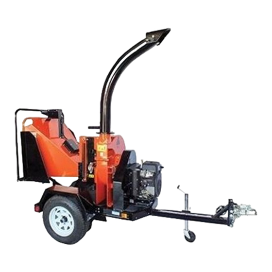
- Page 1 www.bearcatproducts.com 6 INCH CHIPPER CH6720H – 720cc SUBARU PN: 72725-00 Rev. 010117 Companion to 72726-00 Range: 5VJAA0412GW005188 - 5VJAA0412HW005497...
- Page 2 Please read and understand this manual before operating your machine. If you have any questions or comments about this manual, please call us toll-free at 1.888.645.4520. If you have any questions or problems with your machine, please call or write your local authorized ECHO Bear Cat Dealer.
- Page 3 Crary Industries, Inc. In the event of a failure, return the product, at your cost, along with proof of purchase to the selling ECHO Bear Cat dealer. Crary Industries, Inc. will, at its option, repair or replace any parts found to be defective in material or workmanship.
- Page 4 EPA EMISSION CONTROL WARRANTY STATEMENT YOUR WARRANTY RIGHTS AND OBLIGATIONS The California Air Resources Board and Crary Industries Inc. are pleased Any warranted part that is scheduled for replacement as required to explain the evaporative emission control system (EECS) warranty on maintenance in the written instructions supplied is warranted for your current model year equipment.
- Page 5 THIS PAGE INTENTIONALLY LEFT BLANK...
-
Page 6: Table Of Contents
TABLE OF CONTENTS SAFETY ..............1 SERVICE & MAINTENANCE ......18 1.1 SAFETY ALERT SYMBOL ........1 5.1 MAINTENANCE SCHEDULE ......... 18 1.2 EMISSION INFORMATION ........1 5.2 ROTOR LOCK ............19 1.3 BEFORE OPERATING ..........1 5.3 RAISE/LOWER ACCESS COVER ......19 1.4 OPERATION SAFETY .......... -
Page 7: Safety
SAFETY Section arrester muffler in continuous effective working order. The 1.1 SAFETY ALERT SYMBOL spark arrester must be attached to the engine exhaust system in such a manner that flames or heat from the system will not ignite flammable material. Failure of the owner/operator of the equipment to comply with this regulation is a misdemeanor under California law and may also be a violation of other state and/or federal... -
Page 8: Operation Safety
SAFETY 7. Do not operate this equipment in the vicinity of have come to a complete stop before inspecting or bystanders. Keep the area of operation clear of all servicing any part of the machine. Disconnect the persons, particularly small children. It is recommended battery and remove the ignition key if applicable. -
Page 9: Battery Safety
SAFETY 6. Stand to side of feed chute when feeding material and 1.7 MAINTENANCE/STORAGE SAFETY release material quickly. 1. Before inspecting, servicing, storing, or changing 7. When inspecting or servicing the feed roller, secure an accessory, shut off the machine and make sure the feed roller in the raised position using the lock pin, all moving parts have come to a complete stop. -
Page 10: Safety Decals
SAFETY 1.9 SAFETY DECALS See Section 1.10 for decal locations. Familiarize yourself with all of the safety and operating decals on the machine and the associated hazards. See the engine owner's manual or contact the engine manufacturer for engine safety instructions and decals. -
Page 11: Safety Decal Locations
SAFETY PN 32327-00 ENG. & FR. PN 32330-00 ENG. & FR. (32339-00 ESP. & PORT.) (32342-00 ESP. & PORT.) PN 32328-00 ENG. & FR. PN 32332-00 ENG. & FR. (32340-00 ESP. & PORT.) (32341-00 ESP. & PORT.) *Decals 11-14 not for CE compliant machines. 1.10 SAFETY DECAL LOCATIONS The numbers below correspond to the decals in Section 1.9. -
Page 12: Assembly
ASSEMBLY Section 2.1 ATTACH TRAILER WHEELS 1. Remove the chipper from its shipping crate. Place the WARNING unit on a level surface before attempting to assemble. 2. Raise the trailer several inches from the ground with a If any bolts or nuts are dropped in the machine, be sure hoist or jack. -
Page 13: Install Rear Stabilizer
ASSEMBLY feed chute. The other six bolts mount on the outer 2.3 INSTALL REAR STABILIZER flanges of the right and left chute supports through the feed roller housing. Install a coated clamp (3) in the To install the rear stabilizer, slide the stabilizer into the lower left mounting hole. -
Page 14: Attach Digital Display Controller Mount Assembly
ASSEMBLY 2.6 ATTACH DIGITAL DISPLAY CONTROLLER MOUNT ASSEMBLY 1. Remove the bolts (1) and nuts (2) attaching the digital display controller mount assembly (3) to the inside of the chute. 2. Attach mount assembly to the outside of the chute as shown. -
Page 15: Add Oil To Engine
ASSEMBLY 8. Finish bolting the deflector to the tube with two 5/16 2.10 CHECK/ADD HYDRAULIC FLUID x 1" bolts (10) through the end hole in the discharge tube and secure with 5/16" washers and nylock nuts Hydraulic fluid drives the feed roller. The machine was (11). -
Page 16: Features & Controls
FEATURES & CONTROLS Section Understanding how your machine works will help you achieve the best results when using your chipper. The following descriptions define the features and controls of your machine. REFER TO ENGINE OWNER'S MANUAL FOR FURTHER ENGINE OPERATING INSTRUCTIONS. 6 INCH CHIPPER... - Page 17 FEATURES & CONTROLS 1. CHUTE EXTENSION TRAY 12. MANUAL CONTAINER The feed chute has an extension tray that folds down. Conveniently holds your manuals. Raise the extension tray to an upright position and 13. REAR STABILIZER secure with latch before towing the machine. Prevents the chipper from tipping when disconnected 2.
-
Page 18: Operation
OPERATION Section As with any other piece of outdoor equipment, getting the ● For a cold engine: gradually return the choke to the feel for how your machine operates and getting to know OFF position after the engine starts and warms up. the best techniques for particular jobs are important to ●... -
Page 19: Chipper Operation Guidelines
OPERATION 4.3 CHIPPER OPERATION GUIDELINES 9. ALWAYS feed brush from the side of the chipper WARNING chute, rather than from the front. Step aside to avoid being hit by the brush moving into the chipper. Read and follow all safety instructions in this manual. 10. -
Page 20: Slowing And Stopping The Chipper Rotor And Engine
The model number shown should match operation under such conditions can result in plugging of the model of the chipper. If it does not, contact ECHO Bear the discharge, belt damage, and inefficient operation. Cat Service at 1-866-625-4520 for help. - Page 21 OPERATION ● Troubleshooting – Basic troubleshooting information to help diagnose problems with the engine, belt drive or other problems that may occur during chipping. Navigate the screens of this section with the Navigation Button. ● Language – Allows the selection of the language displayed on the controller.
- Page 22 OPERATION Solid Green – The chipping rotor has achieved ● The Total hours on the chipper are shown in the upper left sufficient RPM to begin chipping. The feed roller can corner of the screen. The total hours are based on "Key now be engaged in the forward direction.
-
Page 23: Towing
OPERATION 4.8 TOWING 4.8.1 ATTACHING 4.8.2 DETACHING 1. Rotate the discharge tube to face the opposite 1. Unhook the safety chains from the towing vehicle. direction of the towing vehicle before towing. Latch safety chains to the hitch to prevent them from interfering with chipping. -
Page 24: Service & Maintenance
SERVICE & MAINTENANCE Section 5.1 MAINTENANCE SCHEDULE The items listed in this service and maintenance schedule are to be checked, and if necessary, corrective action taken. This schedule is designed for units operating under normal conditions. If the unit is operating in adverse or severe conditions, it may be necessary for the items to be checked and serviced more frequently. -
Page 25: Rotor Lock
SERVICE & MAINTENANCE WARNING BEFORE INSPECTING OR SERVICING ANY PART OF THIS MACHINE, SHUT OFF POWER SOURCE, DISENGAGE THE HYDRAULICS, OPEN SHIELD AND MAKE SURE ALL MOVING PARTS HAVE COME TO A COMPLETE STOP. 5.2 ROTOR LOCK 5.4 CHIPPER BLADES MAINTENANCE The chipper blades will eventually become dull, making WARNING chipping difficult and adding extra strain on the machine. -
Page 26: Removing The Blades
SERVICE & MAINTENANCE WARNING BEFORE INSPECTING OR SERVICING ANY PART OF THIS MACHINE, SHUT OFF POWER SOURCE, DISENGAGE THE HYDRAULICS, OPEN SHIELD AND MAKE SURE ALL MOVING PARTS HAVE COME TO A COMPLETE STOP. 5. Remove an equal amount off each blade to maintain 5.5 REMOVING THE BLADES rotor balance. -
Page 27: Trailer Maintenance Tips
SERVICE & MAINTENANCE WARNING BEFORE INSPECTING OR SERVICING ANY PART OF THIS MACHINE, SHUT OFF POWER SOURCE, DISENGAGE THE HYDRAULICS, OPEN SHIELD AND MAKE SURE ALL MOVING PARTS HAVE COME TO A COMPLETE STOP. 2. Loosen the three 1/2" bolts that hold the chipper anvil 5.10 CLEARING A PLUGGED ROTOR to the frame. -
Page 28: Drive Belts
SERVICE & MAINTENANCE WARNING BEFORE INSPECTING OR SERVICING ANY PART OF THIS MACHINE, SHUT OFF POWER SOURCE, DISENGAGE THE HYDRAULICS, OPEN SHIELD AND MAKE SURE ALL MOVING PARTS HAVE COME TO A COMPLETE STOP. 9. Turn the check valve counterclockwise to disengage the pump and lower the jack. 10. -
Page 29: Rotor Bearings
SERVICE & MAINTENANCE WARNING BEFORE INSPECTING OR SERVICING ANY PART OF THIS MACHINE, SHUT OFF POWER SOURCE, DISENGAGE THE HYDRAULICS, OPEN SHIELD AND MAKE SURE ALL MOVING PARTS HAVE COME TO A COMPLETE STOP. 5.11.2 REPLACING HYDRAULIC DRIVE BELT 5.12 ROTOR BEARINGS Check the condition of the hydraulic drive belt annually or after every 50 hours of operation, whichever comes first. -
Page 30: Hydraulic Feed Maintenance
SERVICE & MAINTENANCE WARNING BEFORE INSPECTING OR SERVICING ANY PART OF THIS MACHINE, SHUT OFF POWER SOURCE, DISENGAGE THE HYDRAULICS, OPEN SHIELD AND MAKE SURE ALL MOVING PARTS HAVE COME TO A COMPLETE STOP. 5.13 HYDRAULIC FEED MAINTENANCE 5.14 CHANGE HYDRAULIC FLUID FILTER Hydraulic fluid drives the feed roller. -
Page 31: Lubrication
SERVICE & MAINTENANCE WARNING BEFORE INSPECTING OR SERVICING ANY PART OF THIS MACHINE, SHUT OFF POWER SOURCE, DISENGAGE THE HYDRAULICS, OPEN SHIELD AND MAKE SURE ALL MOVING PARTS HAVE COME TO A COMPLETE STOP. 5.16 LUBRICATION WARNING NOTE Do not over grease bearings. Overfilling can lead to Polyurea and lithium-based greases are not compatible. -
Page 32: Troubleshooting
TROUBLESHOOTING Section 6.1 FLASH CODES FOR THE DIGITAL DISPLAY CONTROLLER FREQUENCY CAUSE ACTION TO TAKE GREEN Chipper has reached required RPM Solid Machine ready for chipping and forward feed is available 1/2 second on, Chipper has not reached chipping RPM Slowly increase RPM 1/2 second off upon initial startup... -
Page 33: Troubleshooting Guide
Before performing any of the corrections in this troubleshooting chart, refer to the appropriate information contained in this manual for the correct safety precautions and operating or maintenance procedures. Contact your dealer or ECHO Bear Cat for service problems with the machine. - Page 34 TROUBLESHOOTING PROBLEM POSSIBLE CAUSES REMEDY Dull chipper blades Flip, sharpen, or replace Hard to feed chipper, Use branch or similar object to clear Obstructed discharge requires excessive discharge tube power to chip Set blade/anvil clearance to recommended Improper blade clearance distance Dull chipper blades Flip, sharpen, or replace...
-
Page 35: Specifications
SPECIFICATIONS Section DESCRIPTION ENGLISH METRIC Overall size 126" L x 57" W x 104" H 320 x 145 x 264 cm Overall weight 1,595 lbs. 723 kg Max chipper capacity 6" dia. 15.2 cm dia. Chipper blades 4 reversible (4 x 5.1 x 0.50") 4 reversible (10.2 x 13.0 x 1.3 cm) Chipping anvil 4-edge adjustable... -
Page 36: Bolt Torque
SPECIFICATIONS 7.1 BOLT TORQUE The tables below are for reference purposes only and their use by anyone is entirely voluntary, unless otherwise noted. Reliance on their content for any purpose is at the sole risk of that person and any loss or damage resulting from the use of this information is the responsibility of that person. -
Page 37: Temperature Operating Window
SPECIFICATIONS 7.2 TEMPERATURE OPERATING WINDOW For the nearest Mobil lubricant supplier or technical information, including lubricant information for severe arctic operating conditions, call 1-800-662-4525. EFFECTIVE TEMPERATURE RANGE HYDRAULIC RESERVOIR TEMPERATURE Mobil Mobil Mobil Mobil Mobil Mobil Mobil DTE 10 DTE 10 DTE 10 DTE 10 DTE 10... -
Page 38: Options
OPTIONS Section PART NUMBER DESCRIPTION 14519-00 COUPLER, 2-5/16 20,000 LB. 14900-00 HITCH, PINTLE RING 20,000 LB. 71930-00 KIT, 6" ORCHARD CHUTE 75291-00 KIT, SPARE TIRE 76293-00 KIT, CHIPPER BLADE (1/2 INCH) 76721-00 KIT, BATTERY DISCONNECT 76945-00 KIT, 6 INCH SAFETY BAR 2-5/16"... - Page 39 ECHO BEAR CAT www.bearcatproducts.com 237 NW 12th Street, West Fargo, ND 58078-0849 Phone: 701.282.5520 • Toll Free: 888.645.4520 • Fax: 701.282.9522 E-mail: service@bearcatproducts.com • sales@bearcatproducts.com...