
Related Manuals for Dell SC180


Summary of Contents for Dell SC180
- Page 1 Dell Storage Center SC180 Expansion Enclosure Owner's Manual Regulatory Model: E11J Regulatory Type: E11J001...
- Page 2 © 2016 Dell Inc. All rights reserved. This product is protected by U.S. and international copyright and intellectual property laws. Dell and the Dell logo are trademarks of Dell Inc. in the United States and/or other jurisdictions. All other marks and names mentioned herein may be trademarks of their respective companies.
-
Page 3: Table Of Contents
SC180 Expansion Enclosure Back-Panel Features and Indicators ............10 SC180 Expansion Enclosure EMM Features and Indicators ........11 SC180 Expansion Enclosure Cooling Fan Module Features and Indicators ............12 SC180 Expansion Enclosure PSU Features and Indicators .................. 13 SC180 Expansion Enclosure Drive Numbering .................... - Page 4 ................33 Send Diagnostic Data Using Dell SupportAssist 3 Troubleshooting SC180 Components............34 ..................... 34 Troubleshooting Cooling Fan Modules ........................34 Troubleshooting PSUs ......................34 Troubleshooting Hard Drives ........................35 Troubleshooting EMMs 4 SC180 Expansion Enclosure Technical Specifications........36 ........................36 Technical Specifications...
-
Page 5: About This Guide
Preface About this Guide This guide describes how to perform service and maintenance on the SC180 expansion enclosure. Revision History Document Number: MV429 Revision Date Description March 2015 Initial release June 2016 Updated pre-replacement procedures and clarified requirements Audience The information provided in this guide is intended for use by Dell end users. - Page 6 Help for individual cmdlets is available online. • Dell Storage Manager Client Administrator’s Guide Provides information about the Dell Storage Manager Client and how it can be used to manage a Storage Center. • Dell Storage Manager Administrator’s Guide Provides instructions for using the Data Collector Manager and the Dell Storage Manager Client.
-
Page 7: About The Sc180 Expansion Enclosure
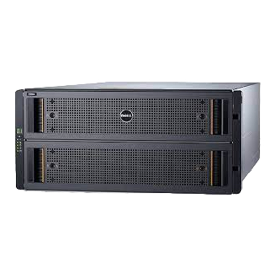
The SC180 expansion enclosure connects directly to the SAS ports on the back of the storage system. SC180 Expansion Enclosure Overview The SC180 is a 5U SAS expansion enclosure that supports up to 84 internal 3.5‐inch hard drives installed in a two‐drawer, three‐row, 14‐column configuration. - Page 8 – Green — Expansion enclosure is on (operational) – Amber — Expansion enclosure is in standby mode (not operational) • Module Fault – Amber — Hardware fault (an LED may be lit on a PSU, drawer, DDIC, fan About the SC180 Expansion Enclosure...
-
Page 9: Sc180 Expansion Enclosure Back-Panel Features And Indicators
On in Storage Client. SC180 Expansion Enclosure Back-Panel Features and Indicators The SC180 back panel shows power, connectivity, and fault indicators. Figure 2. SC180 Expansion Enclosure Back-Panel Features and Indicators About the SC180 Expansion Enclosure... -
Page 10: Sc180 Expansion Enclosure Emm Features And Indicators
Controls power for the expansion enclosure. There is one switch for each power supply. SC180 Expansion Enclosure EMM Features and Indicators An SC180 includes two enclosure management modules (EMMs) in two Storage Bridge Bay (SBB) interface slots. Figure 3. SC180 Expansion Enclosure EMM Features and Indicators... -
Page 11: Sc180 Expansion Enclosure Cooling Fan Module Features And Indicators
Blinking green: SAS PHY is not connected plus activity SC180 Expansion Enclosure Cooling Fan Module Features and Indicators SC180 Expansion Enclosures include five cooling fan modules in five interface slots. Figure 4. SC180 Expansion Enclosure Cooling Fan Module Features and Indicators Item... -
Page 12: Sc180 Expansion Enclosure Psu Features And Indicators
SC180 Expansion Enclosure PSU Features and Indicators SC180 Expansion Enclosures include two power supply units (PSUs) in two interface slots. Figure 5. SC180 Expansion Enclosure PSU Features and Indicators Item Control/Feature Icon Description Release latch — Press the release latch to remove the PSU. -
Page 13: Sc180 Expansion Enclosure Drive Numbering
SC180 Expansion Enclosure Drive Numbering In the SC180 expansion enclosure, the drive slots are numbered 1–42 in the top drawer and 43–84 in the bottom drawer. Dell Storage Client identifies drives as XX-YY, where XX is the number of the unit ID of the expansion enclosure, and YY is the drive position inside the expansion enclosure. - Page 14 Indicator Code • Amber (flashing) — Flashes in 1-second intervals when drive or enclosure indicator is set to On in Dell Storage Client. With the drive indicator, the containing drawer fault LED will also flash. With the enclosure indicator, all drives’ and both drawers’...
-
Page 15: Replacing Sc180 Expansion Enclosure Components
Always follow these safety precautions to avoid injury and damage to Storage Center equipment. If equipment described in this section is used in a manner not specified by Dell, the protection provided by the equipment could be impaired. For your safety and protection, observe the rules described in the following sections. -
Page 16: Electrical Safety Precautions
The resulting electrical discharge can damage electronic components and printed circuit boards. Follow these guidelines to protect your equipment from ESD: • Dell recommends that you always use a static mat and static strap while working on components in the interior of the expansion enclosure chassis. •... -
Page 17: Pre-Replacement Procedures
Shut Down the Storage System If the field replaceable unit (FRU) is not hot-swappable, use the Dell Storage Client to shut down the storage system. Shutting down the storage system results in a system outage, so plan to perform these procedures during a maintenance window. -
Page 18: Replacing Psus
When the storage system is shut down, unplug the power cables from the storage system and expansion enclosures. Replacing PSUs The SC180 expansion enclosure supports two hot-swappable power supply units (PSUs). If one unit fails, the second unit continues to provide power to the expansion enclosure. Identifying the Failed PSU To determine which power supply unit (PSU) failed, use the Dell Storage Client. -
Page 19: Replacing A Psu
Use this procedure to replace a failed power supply unit (PSU). Prerequisites Use SupportAssist to send diagnostic data to Dell Technical Support Services. About this task You can replace PSUs one at a time without shutting down the expansion enclosure. - Page 20 Connect the power cable to the PSU and make sure that the cable is plugged into a power outlet. Secure the power cable using the clip. Figure 11. Securing the power cable Press the power switch on the PSU to turn it on. Replacing SC180 Expansion Enclosure Components...
-
Page 21: Replacing Cooling Fan Modules
When the PSU is functioning properly, the Power OK indicator turns green and the PSU fault and AC fault indicators are off. In the Dell Storage Client, make sure that the replacement PSU is recognized and shown as up and running. -
Page 22: Replacing A Cooling Fan Module
Use this procedure to replace a failed cooling fan module. Prerequisites Use SupportAssist to send diagnostic data to Dell Technical Support Services. About this task You can replace cooling fan modules one at a time without shutting down the expansion enclosure. - Page 23 Battery and Fan fault LEDs are off. In addition, the cooling fan status indicator turns green in the Dell Storage Client. In the Dell Storage Client, make sure that the replacement cooling fan module is recognized and shown as up and running.
-
Page 24: Replacing Hard Drives
Replacing Hard Drives The SC180 expansion enclosure supports up to 84 3.5‐inch hot‐swappable hard drives installed in a two‐ drawer, three‐row, 14‐column configuration. Hard drives are connected to a backplane using Disk Drive in Carrier (DDIC) hard drive carriers. Identifying the Failed Hard Drive To determine which hard drive failed, use the Dell Storage Client. -
Page 25: Replacing A Hard Drive
Hard drives can be replaced one at a time without shutting down the expansion enclosure. Steps Find the SC180 and drawer that contains the failed drive. To identify the drawer with the failed driver, look for a drawer fault LED. - Page 26 Drawer latches (2 per drawer) Drawer (2 per chassis) CAUTION: If the SC180 operates for too long (depending on altitude) with drive drawers open, the enclosure can overheat. Overheating can cause potential drive failure and data loss and could invalidate the warranty.
- Page 27 Install the replacement DDIC. a. Hold the drive by the DDIC and slide it most of the way into the slot. b. Using both hands (thumbs and forefingers), apply downward pressure firmly and equally across the DDIC. Replacing SC180 Expansion Enclosure Components...
- Page 28 Figure 19. Inserting the Drive into the Drawer c. While maintaining downward pressure, slide the top plate of the DDIC toward the back of the drawer until it clicks in place. Figure 20. Securing the Drive in the Drawer Replacing SC180 Expansion Enclosure Components...
- Page 29 WARNING: Keep fingers clear of the chassis as the drawer is closed. In the Dell Storage Client, make sure that the replacement hard drive is recognized and shown as up and running. If the Dell Storage Client informs you that there are unassigned hard drives, see the Dell Storage Manager Client Administrator’s Guide for instructions on managing unassigned hard drives.
-
Page 30: Replacing An Enclosure Management Module
Identifying the Failed Enclosure Management Module To determine which enclosure management module (EMM) failed, use the Dell Storage Client. Start the Dell Storage Client and connect to the Storage Center that has an expansion enclosure with a failed EMM. Click the Hardware tab. -
Page 31: Replacing An Enclosure Management Module
NOTE: Make sure the cables are labeled before disconnecting them from the EMM. Steps Use SupportAssist to send diagnostic data to Dell Technical Support Services. Disconnect the SAS cables connected to the EMM. Push the release tab to the right and pull the release lever away from the chassis. -
Page 32: Replacing Rack Rails
Push the release lever toward the chassis until it clicks into place. Reconnect the SAS cables to the EMM. Replacing Rack Rails Rack rails are used to install the SC180 expansion enclosure into a rack. Prerequisites Use SupportAssist to send diagnostic data to Dell Technical Support Services. -
Page 33: Post-Replacement Procedures
NOTE: Always turn on the expansion enclosure before turning on the storage system. Turn on the storage system by pressing the power switches on the PSUs. Use the Dell Storage Client to make sure the replacement part is recognized and shown as up and running. -
Page 34: Troubleshooting Sc180 Components
Troubleshooting SC180 Components This section contains basic troubleshooting steps for components inside the SC180 expansion enclosures. Troubleshooting Cooling Fan Modules To troubleshoot cooling fan modules: Check the status of the cooling fan module using the Dell Storage Client. Determine the status of the cooling fan module LEDs. -
Page 35: Troubleshooting Emms
Remove the EMM. b. Verify that the pins on the backplane and the EMM are not bent. If any pins are bent, do not attempt to correct them, instead, contact Dell Technical Support Services for further instruction. c. Reinstall the EMM. -
Page 36: Sc180 Expansion Enclosure Technical Specifications
Specifications This section contains technical specifications for SC180 expansion enclosures. Technical Specifications The technical specifications of the SC180 expansion enclosure are displayed in the following tables. Drives SAS hard drives Up to 84 3.5-inch SAS hot-swappable hard drives (6.0 Gbps) - Page 37 One single-color LED indicator for power status Power Supplies AC power supply (per power supply) Wattage 2.8 kW Voltage 200–240 VAC (16 A) Heat dissipation 191-147 W Input frequency 50/60 Hz Max input power 1791 VA Input current 7.4 A@241 VAC SC180 Expansion Enclosure Technical Specifications...
- Page 38 (1°F per 547 feet) above 950 meters (3,117 feet) Storage –40° to 65°C (–40° to 149°F) at a maximum altitude of 12,000 m (39,370 ft) Relative humidity Operating 10% to 80% (noncondensing) with 29°C (84.2°F) maximum dew point SC180 Expansion Enclosure Technical Specifications...
- Page 39 X- and Y-axes: 20 g 10 ms half sine Altitude Operating 0 to 3048 m (–100 to 10,000 ft) Storage –300 m to 12,192 m (–1000 ft to 39,370 ft) Airborne Contaminant Level Class G2 or lower as defined by ISA-S71.04-1985 SC180 Expansion Enclosure Technical Specifications...