Table of Contents
Advertisement
Quick Links
Notice to users
The unauthorized reproduction or replication in whole or in part of this operation manual is prohibited. The prod-
uct's performance, specifications, and appearance may be modified for improvements without advance notice.
Thank you for your understanding.
MABUCHI MOTOR CO., LTD.
DS-34EC1
Instruction Manual
DS-34EC1
Controller
Publication
Number:
Date of Publication: Feb. 24. 2021
TKS-A10-000184
1
Advertisement
Table of Contents

Summary of Contents for MABUCHI MOTOR DS-34EC1
- Page 1 The unauthorized reproduction or replication in whole or in part of this operation manual is prohibited. The prod- uct’s performance, specifications, and appearance may be modified for improvements without advance notice. Thank you for your understanding. MABUCHI MOTOR CO., LTD.
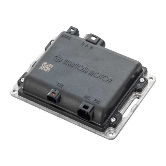
- Page 2 〇 Product overview This product is a controller that drives the Mabuchi Motor brushless motor IS-94 and MS-94 series. It presumes use with mobility or AGV devices equipped with 24V or 36V batteries, with speed control and direction of rotation switching possible through CAN communication.
-
Page 3: Warning
FOR YOUR SAFTY Read the safety warnings for proper use of this product. Mabuchi Motor Co., Ltd. has no liability to indemnify damages, including any malfunction of the motor resulting from failure to follow this operation manual. Thank you for your understanding. - Page 4 Usage and handling - The controller is intended as a general purpose product. It cannot be used with medical, military, aerospace, automotive, or other specialty equipment. - Although the controller is protected by a case, carefully consider its handling and installation location to avoid excessive electrical and mechanical stress.
- Page 5 - Set up an additional mechanism for emergency stop (power off and emergency stop brakes, etc.). Note that even if a drive stop is triggered, the output may not stop due to the setting state or external forces. - Before installing on a machine and starting operations, set the parameters according to the machine being used.
- Page 6 - When an error is detected, rectify the cause of the error and ensure safety. After that, release the error state, turn on the power again, and restore operations. - When disposing of this product, do so according to laws and regulations, and applicable directives from local governments.
- Page 7 Operating temperature range -10℃ to +50℃ Operating humidity range 30%RH to 95%RH (without condensation) Connector lead terminal 105℃ (max.) temperature *1: The power supply voltage, speed, or speed range specified in this instruction manual are described with reference to characteristics when used in combination with IS-94BZC. The characteristics and specifications of MS-94BZA/BZB/BZC must take into account the gear reduction ratio.
- Page 8 ・For details on how to check the temperature of the connector terminals, refer to "5-5. Notes on cable connector terminals ". ・To keep the motor and connector temperature at the specified value (motor 100°C max, connector 105°C max), limit the drive current value by changing the current limit value or forcibly cool down the motor and connectors.
- Page 9 ② CAN communication circuit CAN communication (High Speed Can supported) Communication method CAN2.0B compliant CN_D Pin 4: CAN High level signal Signal connection terminal CN_D Pin 3: CAN Low level signal Data transfer rate 500kbps Line termination resistance 124Ω/open (Selectable) CAN communication internal equivalent circuit Equivalent circuit To MCU...
- Page 10 2. Functional block diagram The following abbreviations of signal names shown in “4. Connector” are shown in a functional block diagram. Connector Abbrevia- Signal name name tion BATTERY POSITIVE CN_A BATTERY NEGATIVE U PHASE OF MOTOR CN_B V PHASE OF MOTOR W PHASE OF MOTOR +5V POSITIVE ELECTRODE THERMISTOR...
- Page 11 3. CAN communication 3-1. CAN ID configuration rules The ID for CAN communication is configured to consist of a function code for the top 4 bits and a node device ID for the lower 7 bits. The function code (FCD) is a number used to identify a particular function. The node device ID (NID) is a number used to identify an individual unit when multiple units are used.
-
Page 12: Warning Code
3.2. Communication details CAN communication settings/readout function (*4, *5) Data contents Direc- Function tion [CAN ID] (*1) (*2) 1Byte 2Byte 3Byte 4Byte 5Byte 6Byte 7Byte 8Byte Operat- Motor speed Motor drive 0x03 (Rotation) Acceleration setting Current limit [0x181,0x182] state set- command setting ting... - Page 13 Function: Motor drive Setting contents Default value command [FCD=0x03] [1bit] 0: motor stop, 1: motor drive [2bit] 0: CCW drive, 1: CW drive Operational state setting [3 to 7bit] - : Invalid setting [8bit] 0: Short brake, 1: Motor free (*1) Motor speed Rotation speed command: 60-3,000 [r/min] (*2) (Rotation setting)
- Page 14 Function: Driving state Reading contents Data range notification 2 [FCD=0x07] Motor moving distance [rotation/42] Moving distance -2147483648〜 For every 1/42 rotation, counted as + when moving in CCW direction and (Traveled distance) +2147483647 - when moving in CW direction (*1) DC voltage Notifies of input DC voltage [V] ×...
- Page 15 Function: Parameter write/read re- Setting contents Default value quest [FCD=0x0B] Data length Valid data length for data 1 to 5 (0 to 5 Byte) ― Read/write number Write/read identification number (0x3B: Write; 0x21: Read) ― WID/PID Write/read identification data number (*1) ―...
-
Page 16: Overheating Warning
Basic response change 0: High response 1: Medium response 2: Low response 0〜2 Response time adjustment 16: High response ⇔ 25: Low re- Disturbance observer 16〜25 Input response time sponse 0x02 High response response 1: Low response ⇔ 255: High re- Disturbance observer 1〜255 Disturbance response... - Page 17 Data Data Default Setting Data name Place- Details length value range ment Node device ID Set the node device ID to identify the 0x10 1〜127 settings controller 0: Do not connect the terminating Terminating resistor 0x12 resistor 0〜1 selection 1: Connect the terminating resistor ①...
- Page 18 - Read request DATA1 DATA2 DATA3 DATA4 DATA5 DATA6 DATA7 DATA8 CAN ID Data WID/PID Data 1 Data 2 Data 3 Data 4 Data 5 Read length 0x581 0x08 0x00 0x21 0x05 0x00 0x00 0x00 0x00 0x00 - Read request response DATA1 DATA2 DATA3...
-
Page 19: Table Of Contents
3-4 Warning Warning Warning Warning detection condition Warning cancellation condition code contents Circuit board temperature 1, 2: Overheating 0x0001 Circuit board temperature: 75℃ or lower warning 90℃ or higher Over speed 0x0002 Speed: 4,000r/min or higher Speed: 3,800r/min or lower warning Low voltage Power supply voltage: 16.5V or... -
Page 20: Speed: 50R/Min Or Lower
3-5. Errors (*1) Error Error contents Error detection conditions Error cancellation condition *3 Code All temperatures 75°C or 0x0001 Overheating error Circuit board temperature 1, 2:100℃ or higher lower, and [Operating state setting=0] Speed: 150r/min or lower, and 0x0002 Over speed error Speed: 4,500r/min or higher [Operating state setting=0] Power supply voltage: 16.5V or... - Page 21 3-6. CAN communication flow Power on Receives CAN communication command for the controller (FCD=0x03, 0x07,0x09,0x0A,0x0B) 10 sec have elapsed since startup After turning on the power and starting the system, wait at least 0.3 sec before starting communication.
- Page 22 CAN communication: circuit command setting: FCD=0x09 setting [command mode: 1] Error event Request data interval elapses (FCD=0x09 setting value) CAN communication: motor state notification/error state notification: Notify controller status at FCD = 0x05 / 0x06 / 0x07 CAN communication: motor drive command: FCD=0x03 received Determines motor operation CAN communication: parameter...
- Page 23 CAN communication: error state notification notifies the error status (FCD: 0x06) Request data interval elapses (FCD=0x09 setting value) CAN communication: motor state notification/error state notification: Notify controller status at FCD = 0x05 / 0x06 / 0x07 CAN communication motor drive command FCD=0x03 re- ceived Determines motor operation Error recovery...
- Page 24 4. Connectors Connector and signal name and function CN_A Connector type: Conforms to Sumiko Tech CL07D02M Terminal Appearance Signal name Function number BATTERY POSITIVE Controller power supply BATTERY NEGATIVE CN_B Connector type: Conforms to Sumiko Tech CL07D03M Terminal Appearance Signal name Function number U PHASE OF MOTOR...
- Page 25 5. Precautions 5-1. Speed setting method ① Speed setting method by CAN communication command. The motor will be driven by setting 1 in the first bit of the operation status setting (= First byte) in the “motor drive commands” by CAN communication. At the same time, by setting the motor operating speed and acceleration, it operates with the set values as targets.
- Page 26 5-3. Notes on battery connections ① Reverse-battery connection The controller circuit does not provide protection against reverse battery connection. Select protection elements such as clamping diodes and fuses and take appropriate measures. ② Residual voltage when battery is shut off The current consumption between B+ and B- terminals during standby is kept low at 0.5mA or less (when 36V).
- Page 27 5-4. Start and stop methods ① How to start and stop using the ON/OFF port after battery connection After connecting the battery, provided the battery voltage is 12V or more, setting the ON/OFF port to ON can be used to start DC/DC converter. The system starts when the DC / DC output is 3.2V or higher, and normal operation is possible after 120msec.
- Page 28 5-5. Notes on cable connector terminals Note that the cable terminals of the connectors CN_A (controller power supply) and CN_B (motor power supply) generate heat when the motor is driven. Please use it so that the specified temperature of the lead terminal is 105℃ or less when the actual machine is installed and the environmental temperature is maximum.
- Page 29 4 x M4 screws (sold separately) *Use 4x M4 screws to affix the controller to a flat metal surface such that there is sufficient heat dissipation 7. Optional items (cables sold separately) Controller (DS-34EC1) ③ DC power - Cable connection diagram battery ①...
- Page 30 *・The motor unit and controller do not come with included connection cables or extension cables. Select a separately sold cable to meet your use case. ・DC power, battery, CAN communication circuit, and ON_OFF circuit are not included. Purchase these separately. ①...
- Page 31 ④ Controller signal cable Part number: 41-L12XA Cable length: 1m *1:The stripped side of the controller power cable and the controller signal cable is not waterproof. When connecting to terminals, place the connection point in a place where it will not be splashed with water. 8.