
Related Manuals for Bang & Olufsen BeoLab 17


Summary of Contents for Bang & Olufsen BeoLab 17
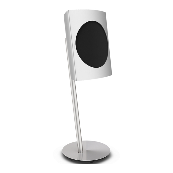
- Page 1 BeoLab 17 Type 6602 - 6603, 6606 - 6609, 6612 - 6614 BeoLab 17 MK II Type 6619, 6622 - 6628 Before serial no. 25010056 Service Manual - version 1.2 English...
-
Page 2: Table Of Contents
CONTENTS Survey of modules ................ 1.1 How to service ................1.2 Troubleshooting - Fault flow chart ..........2.1 Adjustments .................. 3.1 Replacement of modules ............... 4.1 Specification guidelines for service use .......... 5.1 Block diagram ................6.1 Wiring diagram ................6.3 Available parts ................ -
Page 3: Survey Of Modules
Survey of modules Survey of modules 82.3 82.1 82.2 82.4 Modules: PCB02 Connector PCB04 Power Supply PCB30 Digital Sound Engine PCB35 Amplifier PCB47 LED Indicator PCB48 PCB89 Wireless Power Link Rx Antennas: 82.1 Wireless Antenna 82.2 Wireless Antenna 82.3 Wireless Antenna 82.4 Wireless Antenna Speaker units:... -
Page 4: How To Service
How to service How to service Strategy This product is to be serviced in the customer’s home. The repair involves replacement of the module(s), which are supplied in the back- up suitcase. The replaced modules must be returned for repair at the Bang & Olufsen Module Repair department. - Page 5 How to service Warnings when handling Static electricity Static electricity may damage the product. The integrated circuits operates with STATIC ELECTRICITY very low voltages, and that makes the product extremely sensetive to static MAY DESTROY THE PRODUCT electricity. Static-protective field service kit A static-protective field service kit must always be used when the product is disassembled or modules are being handled, since the internal electronics are very sensitive to static electricity.
-
Page 7: Troubleshooting - Fault Flow Chart
Troubleshooting - Fault flow chart Troubleshooting LED indicator ................... 2.2 Description of LED indications ............2.2 Product Information - Usage data ............ 2.3 Error Log ..................2.3 Speaker unit test ................2.4 NTC module test ................2.4 Sound test ..................2.5 Fault flow chart No function and no LED indication ........... -
Page 8: Troubleshooting
Troubleshooting Troubleshooting LED indicator The LED at the front of the speaker indicates the state of the product by changing colour (red/orange/green), flashing or solid. If errors occur during operation, the product will enter an error state and the LED will start flashing quickly orange. Description of LED indications - Green Solid (10 seconds duration):... -
Page 9: Product Information - Usage Data
- Be sure that ServiceTool is updated to the latest version. If not, upgrade and restart ServiceTool. - Scroll down to BeoLab section. - Select BeoLab 17 and click Launch. - Click on the PRODUCT tab (if not already shown). - Click + next to each item to expand the menus. -
Page 10: Speaker Unit Test
Troubleshooting Speaker unit test Measure the DC resistance of the speaker unit to determine if the fault is caused by a defective speaker unit. It is recommended to measure on the terminals on the speaker unit. The speaker units must be disconnected from the product. Speaker unit Nominal value Limits... -
Page 11: Sound Test
- Be sure that ServiceTool is updated to the latest version. If not, upgrade and restart ServiceTool. - Scroll down to BeoLab section. - Select BeoLab 17 and click Launch. - Click on the PRODUCT tab (if not already shown). - Click + next to each item to expand the menus. -
Page 12: Fault Flow Chart
-28V at PCB04, P4 pin 7, 8 Power Supply Replace PCB35, Amplifier Use ServiceTool to Set BeoLab 17 in service position 2 calibrate the new for measuring on modules. See module replacement of modules page 4.8 Survey of plugs and pins - see page 2.13... -
Page 13: Led Indicator Is Flashing Slowly Orange
Fault flow chart Fault symptom: LED indicator is flashing slowly orange (the product is close to overheating) Possible causes: Defective PCB30, Digital Sound Engine Defective PCB35, Amplifier Defective PCB48, NTC Defective speaker unit Disconnect product from mains, wait 2 Read out the Replace the minutes and temperature **... -
Page 14: Led Indicator Is Flashing Quickly Orange
Fault flow chart Fault symptom: LED indicator is flashing quickly orange (The product is in protection mode) Possible causes: Defective PCB30, Digital Sound Engine Defective PCB35, Amplifier Defective PCB48, NTC Defective speaker unit Disconnect product Connect ServiceTool Make an from mains, wait 2 and read out product ID. -
Page 15: No Sound From Speaker In A Wired Setup
Digital Sound Engine Any suggestions? Replace the suspected module related to the Error Log Set BeoLab 17 in service position 2 for measuring on modules. See replacement of modules page 4.8 Survey of plugs and pins - see page 2.13... -
Page 16: No Sound From Speaker In A Wireless Setup
Replace the Replace PCB89, suspected module Wireless Power related to the Link Rx Error Log Set BeoLab 17 in service position 2 for measuring on modules. See replacement of modules page 4.8 Survey of plugs and pins - see page 2.13... -
Page 17: The Signal For Wireless Connection Is Low
Antenna one by Use Wi-Spy (Wi-Spy DBx + Chanalyzer Pro) to visualize which 5 GHz channels are used Set BeoLab 17 in service position 2 and to see if there are other wireless systems for measuring on modules. See in the area, that could cause replacement of modules page 4.8... -
Page 18: Distorted Sound From Speaker
Replace the Replace PCB89, suspected module Wireless Power related to the Link Rx error log Set BeoLab 17 in service position 2 for measuring on modules. See replacement of modules page 4.8 Survey of plugs and pins - see page 2.13... - Page 19 Survey of plugs and pins 2.13 2.13 Survey of plugs and pins 2.13 PCB04, Power Supply PCB89, Wireless Power Link Rx...
- Page 20 2.14 2.14 2.14...
-
Page 21: Adjustments
Adjustments - Final check after repair Adjustments Information ..................3.2 PCB30, Digital Sound Engine ............3.3 PCB35, Amplifier ................3.3 PCB89, Wireless Power Link Rx - when backup function is possible ..3.4 PCB89, Wireless Power Link Rx - when backup function is not possible .. 3.5 Speaker units ................... -
Page 22: Information
Adjustments Adjustments Information Depending on the repair there might be different kinds of adjustments/alignment to be performed, after maintenance of the product. Some adjustments has to be done with ServiceTool. Adjustments or calibration is necessary when the following modules are replaced: PCB30, Digital Sound Engine - when backup function is possible: - Restore product data from the data backup - Calibration of the amplifier (done automatically) - Page 23 - Product settings - Wireless data - A new calibration of the amplifier is performed again. Connect ServiceTool, launch BeoLab 17 and follow the procedure under Repair -> Chassis. ID Restore The ID Restore function is used when PCB30, Digital Sound Engine is replaced and it is not possible to communicate with the old module.
- Page 24 - Product settings - Wireless data - A new calibration of the amplifier is performed again. Connect ServiceTool, launch BeoLab 17 and follow the procedure under Repair -> Chassis. Connecting speaker wirelessly After replacement of PCB89, Wireless Power Link Rx the speaker must be set up in the wireless system correctly.
-
Page 25: Speaker Units
Replace The replace function in ServiceTool is used when it is not possible to perform a Backup/Restore of the module. Connect ServiceTool, launch BeoLab 17 and follow the procedure under Repair -> Chassis. Connecting speaker wirelessly After replacement of PCB89, Wireless Power Link Rx the speaker must be set up in the wireless system correctly. -
Page 26: Software Update
- Be sure that ServiceTool is updated to the latest version. If not, upgrade and restart ServiceTool. - Scroll down to BeoLab section. - Select BeoLab 17 and click Launch. - Click on the PRODUCT tab (if not already shown). - Click + next to each item to expand the menus. -
Page 27: Final Check After Repair
Final check after repair Final check after repair The final check after repair describes the activities that are needed to ensure the product will be returned in perfect condition to the customer. Follow the procedures below: Insulation test The product must be insulation tested after having been dismantled. Make the test when the product has been reassembled and is ready to be returned to the customer. - Page 29 All modules must be placed on the ESD-mat or in an ESD-proof bag. After replacement of modules - When BeoLab 17 has been disassembled, all affected sealings must be visually checked and replaced, if damaged. - Calibration of speaker driver is necessary when a speaker unit is replaced. Refer to adjustment page 3.5.
-
Page 30: Replacement Of Modules
Replacement of modules Remove cover - Pull off end cap if present - Remove screws and pull off cover ! Screws include washers 16mm... -
Page 31: Beolab 17 In Service Position 1
Replacement of modules BeoLab 17 in service position 1 ☞ 4.2 Remove cover - Remove screws ! Screws include washers 16mm TX20 - Remove screws ! When reassembling use peeler tool to center screw bosses 16mm TX20 - Gently pull up bottom cover... - Page 32 Replacement of modules - Disconnect cables Ground 35P1 35P3 35P2 - Remove screw and wire cover if present 16mm - Remove screw ! Screw include a washer 20mm TX20 - Turn around the speaker - Remove screws ! Screws include washers ! Only one type of screws is present.
- Page 33 Replacement of modules - Remove screws and remove woofer 12mm TX10 - Remove screws (only present after serial number 23923287) TX10 - Turn around the speaker - Pull off end cap if present - Remove screws ! Screws include washers 16mm TX20...
- Page 34 Replacement of modules - Remove screws and wire clip ! Screws include washers ! Note placement of wire clip 55mm TX20 - Turn around the speaker - Push and slide out the chassis approx 10 cm. ! Attention cables - Disconnect antenna wire with the special tool, Extraction jig, U.FL series and gently pull out the antenna cable through the ferrite core ! When disconnecting antenna wire be careful...
- Page 35 Replacement of modules - When reassembling remember correct placement of springs if present Correct placement - When reassembling remember correct placement of insulation Correct placement...
-
Page 36: Beolab 17 In Service Position 2
Replacement of modules BeoLab 17 in service position 2 ☞ 4.2 Remove cover ☞ 4.3 BeoLab 17 in service position 1 - Mount woofer and screws 12mm TX10 - Connect woofer with speaker and NTC wires NTC wire Speaker wires - Turn around chassis... - Page 37 Replacement of modules - Mount PCB35, Amplifier with screws and washers TX10 - Connect cables PCB35P1 PCB35P3 PCB35P2...
-
Page 38: Replace Pcb02, Connector
4.10 Replacement of modules Replace PCB02, Connector ☞ 4.2 Remove cover ☞ 4.3 BeoLab 17 in service position 1 - Disconnect cables ! Unlock plugs before disconnecting cables 30P1 !! Note placement of W2 mains cable 30P2 04P1 - Turn around chassis... - Page 39 Replacement of modules 4.11 - Disconnect cables and remove insulation ! When reassembling remember correct placement of cables 02P101 02P102 - Remove screws TX10 - Remove screw ! Screw include a plastic washer TX10 - Turn around the top chassis - Remove screw TX10...
- Page 40 4.12 Replacement of modules - Turn around the top chassis - Replace PCB02, Connector - Move EMC gasket to the new PCB or mount new, if damaged. EMC Gasket...
-
Page 41: Replace Pcb04, Power Supply
Replacement of modules 4.13 Replace PCB04, Power Supply ☞ 4.2 Remove cover ☞ 4.3 BeoLab 17 in service position 1 - Cut off cable tie ! When reassembling mount new cable tie Cable tie - Disconnect cables 04P4 04P3 04P1 - Loosen screws and pull off shielding plate... -
Page 42: Replace Pcb30, Digital Sound Engine
4.14 Replacement of modules Replace PCB30, Digital Sound Engine ☞ 4.2 Remove cover ☞ 4.3 BeoLab 17 in service position 1 - Disconnect cables ! Unlock plugs before disconnecting cables 30P1 !! Note placement of W2 mains cable 30P2 04P1 - Turn around the chassis... - Page 43 Replacement of modules 4.15 - Remove screws ! Screws includes plastic washers - Gently disconnect and pull off module 30P7 TX10 - Disconnect cables and replace PCB30, Digital Sound Engine 30P4 30P3...
-
Page 44: Replace Pcb35, Amplifier
4.16 Replacement of modules Replace PCB35, Amplifier ☞ 4.2 Remove cover ☞ 4.3 BeoLab 17 in service position 1 - Remove screws TX10 - Remove screws and replace PCB35, Amplifier ! Screws include washers TX10... -
Page 45: Replace Pcb47, Led Indicator
Replacement of modules 4.17 Replace PCB47, LED Indicator ☞ 4.2 Remove cover ☞ 4.3 BeoLab 17 in service position 1 - Disconnect cable 47P1 - Remove screws and replace PCB47, LED Indicator TX10... -
Page 46: Replace Pcb48, Ntc
4.18 Replacement of modules Replace PCB48, NTC ☞ 4.2 Remove cover ☞ 4.26 Remove woofer - Remove screw TX10 - Replace PCB48, NTC... -
Page 47: Replace Pcb89, Wireless Power Link Rx
Replacement of modules 4.19 Replace PCB89, Wireless Power Link Rx ☞ 4.2 Remove cover ☞ 4.3 BeoLab 17 in service position 1 ☞ 4.14 Remove PCB30, Digital Sound Engine - Remove screws and gently pull off PCB89, Wireless Power Link Rx ! Attention antenna wires... -
Page 48: Antennas
4.20 Replacement of modules Replace 82.1, Wireless Antenna ☞ 4.2 Remove cover ☞ 4.3 BeoLab 17 in service position 1 - Remove screws and pull off 82.1, Wireless Antenna 10mm TX10 ☞ 4.14 Remove PCB30, Digital Sound Engine ☞ 4.19 Remove PCB89, Wireless Power Link Rx - Follow the wire from 82.1, Wireless Antenna... -
Page 49: Replace 82.2, Wireless Antenna
Replacement of modules 4.21 Replace 82.2, Wireless Antenna ☞ 4.2 Remove cover ☞ 4.3 BeoLab 17 in service position 1 - Remove screws and replace 82.2, Wireless Antenna ! When reassembling, be careful not to tighten the screws too hard. ! It is very important that the gasket around the antenna is OK. -
Page 50: Replace 82.3, Wireless Antenna
4.22 Replacement of modules Replace 82.3, Wireless Antenna ☞ 4.2 Remove cover ☞ 4.3 BeoLab 17 in service position 1 ☞ 4.14 Remove PCB30, Digital Sound Engine ☞ 4.19 Remove PCB89, Wireless Power Link Rx - Remove screws and pull off 82.3, Wireless Antenna... -
Page 51: Replace 82.4, Wireless Antenna
Replacement of modules 4.23 Replace 82.4, Wireless Antenna ☞ 4.2 Remove cover ☞ 4.3 BeoLab 17 in service position 1 - Cut off cable tie ! When reassembling mount new cable tie Cable tie ☞ 4.14 Remove PCB30, Digital Sound Engine ☞ 4.19 Remove PCB89, Wireless Power Link Rx - Follow the wire from 82.4, Wireless Antenna... -
Page 52: Wireless Antennas (Disconnect And Connect)
4.24 Replacement of modules Wireless Antennas (disconnect and connect) Disconnecting Wireless Antennas - Disconnect antenna wire with the special tool, Extraction jig, U.FL series. Pull gently perpendicular to the PCB89 via the chain. ! When disconnecting antenna wires be careful not to damage the antenna plug or wire. -
Page 53: Replace Tweeter
Replacement of modules 4.25 Replace tweeter ☞ 4.2 Remove cover - Remove screws 10mm TX10 - Gently pull out tweeter - Disconnect wires and replace tweeter Speaker wires... -
Page 54: Replace Woofer
4.26 Replacement of modules Replace woofer ☞ 4.2 Remove cover - Remove screw and wire cover if present - Remove screw ! Screw include a washer 20mm TX20 - Turn around the speaker and remove screws 12mm TX10 - Gently pull out woofer and disconnect wires - Remove screw and NTC module and replace woofer TX10... -
Page 55: Specification Guidelines For Service Use
Specification guidelines for service use Specification guidelines BeoLab 17 Type survey Market Variant Type number Type number MK I MK II Albania, Andorra, Argentina, Austria, Azerbaijan, Bahrain, Belgium, Botswana, 6602 Bulgaria, Chile, Côte d’Ivory, Croatia, Czech Republic, Denmark, Egypt, Faroe... - Page 56 Specification guidelines for service use Features Adaptive Bass Linearisation (ABL) Room adaptation (Free - Wall - Corner) Thermal protection (NTC sensor) Line sense - auto on/off Wireless Power Link Wireless Technology WiSA 5 GHz *EFFECTIVE FREQUENCY RANGE is measured at -10 dB re. Ref level (200-2000 Hz) **SENSITIVITY is measured at dB SPL 1 m re 125 mV Connections MAINS INLET...
-
Page 57: Block Diagram
Block diagram Block diagram Block diagram AMP_EN_N PCB48, NTC PCB89, Wireless Power PCB30, Digital Sound Engine DC_ERR_N Link Rx 3V3_SB NTC1 NTC1 LRCLK ADC_MUX PL_DATA SCLK ADC_MUX_AX PS_ON PL_ON UART_TX MAINS_FAIL UART_TX UART_RX nLINK PWR_NTC UART_RX nHEARTBEAT PCB47, LED Indicator AUDIO_MUX_SEL LINE_SENSE_LINE PING1... -
Page 59: Wiring Diagram
Wiring diagram Wiring diagram Wiring diagram Antenna Antenna Antenna Wireless Power Link Rx Antenna Connector Ground connector Digital Sound Engine LED Indicator Amplifier Power Supply... - Page 60 Available parts Available parts Available parts BeoLab 17 BeoLab 17 MKII 9001 See pos. no. 9001 4 x End caps 9006 9007 2 x End caps w/legs 82.2 9008 2 x pos. no. 9008 Cover f/wire Incl. pos. no. 9004, 9007,...
-
Page 61: Available Parts
3454475 End caps, white BeoLab 17 3454476 End caps, black BeoLab 17 MKII 9002 3431757 Cabinet, silver incl. pos. no. 9004, 9007 and 7, 9, 11, 13, 16 3431787 Cabinet, black incl. pos. no. 9004, 9007 and 7, 9, 11, 13, 16 3431801 Cabinet, white incl. - Page 62 Available parts Top chassis Before serial no. 23923287 From serial no. 23923287 9020 9021 9020 9022 9025 82.3 Incl. pos. no. 9021 and 15, 20, 25, 27, 30, 31 9026 9027...
- Page 63 Available parts Top chassis 9020 3340582 Metal plate - before serial no. 23923287 3340593 Metal plate - from serial no. 23923287 9021 3340552 Gasket 9022 3321909 Insulation 9025 3454339 Plate f/antenna 9026 3459674 Top incl. pos. no. 9021, 9023 and 15, 20, 25, 27, 30, 31 9027 3340377 Gasket f/AC inlet...
- Page 64 Available parts Chassis 9037 9030 9031 9032 9038 82.1 9033 Incl. 2 x pos. no. 50 9039 9034 *Remember to order pos. no. 9035 9034 9036...
- Page 65 Available parts Chassis 9030 3153728 Holder 9031 3321873 Light guide 9032 3340496 Sealing 9033 3454339 Plate f/antenna 9034 3152823 Cable tie 9035 3160817 Insulation 9036 3321872 Shielding plate 9037 8480516 Woofer 9038 8480436 Tweeter 9039 3340581 Baffle incl. 2 x pos. no. 50 04Module 8007885 PCB04, Power Supply – Remember to order pos. no. 9034 30Module 8007882 PCB30, Digital Sound Engine 47Module 8007884...
- Page 66 Available parts Wires 6033084 Wire, GND 6278870 Wire, Mains inlet See page 6.3 6033084 Wire, GND 6278904 Wire bundle, PSU-DSE-AMP 6200538 Wire, 30 pole 6200537 Wire, 24 pole 6278873 Wire, DSE-AMP 6278874 Wire, AMP-SPK Parts not shown 3658262 Product cover (2 pcs.) 3506000 Template –...
- Page 67 Available parts Floor Base - type 2113 1211313 Silver Not for sale 1211326 Black 2042047 Screw 4 x 10mm 3103511 Bumper 3393983 Packing 3040057 Allen key Guide Can be downloaded from BeoWise Wall Bracket - type 2114 1211413 Silver Not for sale 2042047 Screw 4 x 10mm 2042060...
- Page 68 Available parts Floor Stand, high - type 2112 1211213 Silver 1211226 Black 9050 9050 9051* *9051 9052* *9052 9053* *9053 *Remember to order pos. no. 9050 9055 9054...
- Page 69 Available parts 7.10 Floor Stand, high - type 2112 9050 3321989 Top plate, silver 3321627 Top plate, black 1211213 Silver 9051* 3321936 Locking piece – Remember to order pos. no. 9050 1211226 Black 9052* 3153829 Interface floor stand – Remember to order pos. no. 9050 9053* 2950338 Tube, silver – Remember to order pos. no. 9050 2950358 Tube, black –...
- Page 70 7.11...
- Page 72 Bang & Olufsen DK-7600 Struer Denmark 3538233 16-02...