Table of Contents
Advertisement
Quick Links
OPERATION MANUAL
OPERATION MANUAL
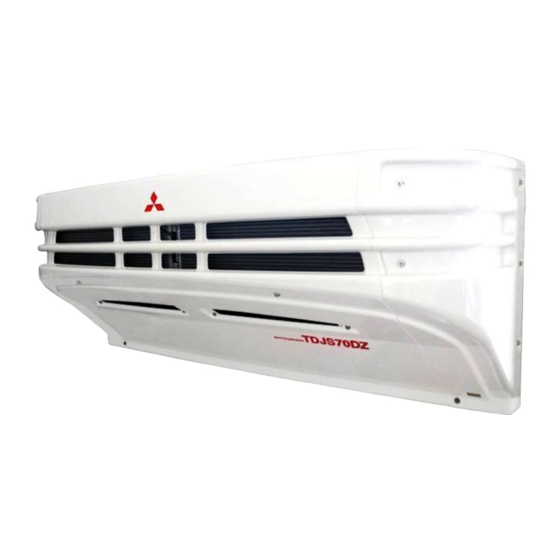
MITSUBISHI TRANSPORT REFRIGERATION UNIT
TDJS Series
This operation manual is
intended to provide users
with a good knowledge to
use Mitsubishi Refrigeration
Unit safely.
Operate or service the
refrigeration unit only after
you have read this manual
and understand its
contents.
Carefully store this manual
immediately available for
your reference when you
need it.
Original Instructions
TSJ012A222
B
YEAR:2022
Advertisement
Table of Contents

Related Manuals for Mitsubishi TDJS Series


Summary of Contents for Mitsubishi TDJS Series
- Page 1 OPERATION MANUAL OPERATION MANUAL MITSUBISHI TRANSPORT REFRIGERATION UNIT TDJS Series This operation manual is intended to provide users with a good knowledge to use Mitsubishi Refrigeration Unit safely. Operate or service the refrigeration unit only after you have read this manual and understand its contents.
-
Page 2: Important Information
Thank you for your purchase of Mitsubishi Transport Refrigeration Unit. Purpose of use and application This Refrigeration Unit is intended to carry the cargo (with the exception of volatile, inflammable, hazardous and corrosive matters) on a transportation vehicle, keeping the inside container temperature at a certain degree. -
Page 3: Operation Manual
Operation manual ● This operation manual is prepared for people who speaks English. In case that person whose native language is not English handles this refrigeration unit, he or she must be instructed on safety by the customer. Furthermore, the warning labels described in their native language must be prepared and stuck on the proper places. -
Page 4: Information On The Models
Information on the Models This operation manual describes how to use the following models. (1) Standard system for single refrigeration compartment Integral type TDJS35*E / TDJS50*E / TDJS70*ZE ■ (2) 2-evaporator system for two refrigeration compartments Integral type TDJS35*E-M / TDJS50*E-M / TDJS70*E-M ■... -
Page 5: Table Of Contents
Contents Purpose of use and application Reinstallation of refrigeration ----------------------------------- 16 unit ------------ I Important information Modification of refrigeration unit ----------------II Operation manual ---------- 16 and specification change -----------------------II For disposal Emergency measures ---------- 17 ----- III Information on the models ---- 19 Handling of warning labels Contents --------------------------IV... - Page 6 9 For emergency ---------- 52 ------- 35 Setting the temperature Setting the preset temperature --- 36 Alarm display ------------------- 52 Manual defrost operation ------ 37 Switching "Normal display" and "Alarm display" ----------------- 52 Starting the manual defrost --------------------------- 37 operation Switching from "Normal display screen"...
-
Page 7: Function Of Refrigeration Unit
1 Function of Refrigeration Unit This refrigeration unit has following functions. (1) Defrosting operation function This is the function to protect evaporator from frosting during cooling operation and to prevent refrigerating power from decreasing. There are following 2 methods to start defrosting operation. Automatic defrosting operation Defrosting starts automatically by the timer setting. -
Page 8: Name Of Each Part
2 Name of each part Arrangement plan for main parts ■Single compartment integral type Refrigeration unit Cabin controller Control box Compressor · Actual locations of above units, etc. should be checked beforehand because they could vary depending on vehicle models, or other. - 2 - - 2 -... - Page 9 2 Name of each part ■2-compartment integral type Refrigeration unit Compressor Control box Rear evaporator unit Cabin controller Actual locations of above units, etc. should be checked beforehand because they could vary depending on vehicle models, or other. - 3 - - 3 -...
-
Page 10: Refrigeration Unit (Integral Type)
2 Name of each part Refrigeration unit (Integral type) Top view Front view Rear view Evaporator outlet Sight glass Evaporator fan motor Condenser coil Dryer Condenser fan motor Evaporator coil Label (F-Gas) Expansion valve · Form of components and specifications may vary depending on models. - 4 - - 4 -... -
Page 11: Rear Evaporator Unit (2-Compartment Model)
2 Name of each part Rear evaporator unit (2-compartment model) Inside of view "A" Evaporator outlet Evaporator coil Evaporator fan motor Expansion valve · Form of components and specifications may vary depending on models. - 5 - - 5 -... -
Page 12: Compressor
2 Name of each part Compressor CS55 CSA90, CSA150 Compressor Magnet clutch · Form of components and specifications may vary depending on models. Control box · Form of components and specifications may vary depending on models. - 6 - - 6 -... -
Page 13: Cabin Controller
Cabin controller ー Cooling RUN/STOP MENU ° C ° C DEFROST ▲ ▼ PRESET 2-compartment model Cooling Heating ° C ° C ° C ° C A Setting B Setting RUN/STOP switch Starts and stops the refrigeration unit. Selects the normal display screen or the menu display MENU switch screen. -
Page 14: Digital Display Area
Digital display area Cooling ° C ° C ▲ ▼ 2-compartment model Cooling Heating ° C ° C ° C ° C A Setting B Setting Description of monitor display item Monitor displays following items corresponding to respective setting states. The display items light or blink depending on the operation of respective functions. - Page 15 Displays the operation modes. <Display contents> Cooling, Heating, Defrost, Sleep, Stop and Fan. * There is no display when Thermostat is OFF with evaporator fan motor OFF. Fan is displayed when Thermostat is OFF with evaporator fan motor ON. If temperature is out of adequate range, the Cooling or Heating display blinks.
-
Page 16: Protective Devices
2 Name of each part Protective devices This refrigeration unit is provided with the following protective devices to ensure the safety of the operators. (1) Panel, Fan guard These devices prevent interference with the rotating section (fan motor) during operation. People who handle this refrigeration unit are requested to understand the functions of these protective devices completely to use it safely. -
Page 17: Precaution For Safety
3 Precaution for safety 1 Aaaaaa In this section, necessary safety precautions are provided to prevent accidents resulting in injuries or death, property damages and environment pollution. Read and understand contents of the cautions before starting to use this Refrigeration Unit. Signs on safety Signs and Symbols on safety in this operation manual and the warning labels call the attention of the people who handle this refrigeration unit. -
Page 18: Precautions
3 Precaution for safety Precautions General precautions DANGER Do not modify or perform specification change for the refrigeration and vehicle. (This will make refrigeration unit out of warranty.) • It may cause a serious accident if customer modify the refrigeration unit or change the specification by himself/herself. -
Page 19: During And After The Operation
3 Precaution for safety WARNING Be sure to carry out the periodic inspections. • Otherwise, it may cause troubles of the refrigeration unit or accidents. CAUTION Do not insert sticks or fingers into cold air outlet or inlet. • Otherwise, it may cause trouble on the equipment or injury by the fan. Do not climb up, hang down or put your leg onto the refrigeration unit. -
Page 20: Inspection/Cleaning/Repair
3 Precaution for safety Inspection/Cleaning/Repair WARNING Do not disassemble and repair by yourself. • Otherwise, it may cause damages or an electric shock. CAUTION When refrigerant or refrigerating machine oil has spilled, take care not get it in eyes and avoid accidental contact to skin or inhaling or swallowing. -
Page 21: Loading
3 Precaution for safety Loading WARNING Do not load the volatile or inflammable cargos in the container. • Otherwise, it may cause an explosion or a fire. CAUTION Cool down or heat up the cargos to the designated temperature in advance with other refrigerating device. •... -
Page 22: Handling Of Electric Equipment And Power Codes
3 Precaution for safety Handling of electric equipment and power codes WARNING • Do not directly splash water on the electric equipment or wash them with water. • Never touch the electric equipment or operate the switches with wet hands. •... -
Page 23: Emergency Measures
3 Precaution for safety Emergency measures (1) Refrigerant When refrigerant got in your eye ● Wash your eye with lots of clean running water for more than 15 minutes immediately. Wash rear side of the eyelid as well. Then, consult a physician as soon as possible. - Page 24 3 Precaution for safety ● When swallowing compressor oil Do not throw up the oil by force and consult a physician as soon as possible. When inside the mouth is contaminated, wash it well with water. (When throwing up the oil by force, it easily gets into air passage and causes high fever if it gets into lung.
-
Page 25: Handling Of Warning Labels
Handling of warning labels Handling of warning labels (a) Important precautions are stated on the warning labels. Never operate Important pr ecautions ar e stated on the war ning labels. Never operate the refrigeration unit unless fully understanding the meanings of the the refrigeration unit unless fully understanding the meanings of the warning labels. - Page 26 3 Precaution for safety Right side view inside TDJS35�E, TDJS35�E-M only PSA011H011A *3 Warning about the hot gas pipe in the unit Left side view inside Control box 1 compartment model PSA011H011 Rear evaporator unit Bottom view PSA011H011A TSJ011H023A Compressor CS55 CSA90, CSA150 - 20 -...
-
Page 27: Prevention Of Start During Inspection Work
3 Precaution for safety Prevention of start during inspection work When several people are working simultaneously for inspection, it is necessary to protect them from getting injured by accidental start of operation. In such occasion, place a tag stating "WORKING" on the cabin controller . Clothing and protective equipment Wear proper clothing and protective equipment to prevent from getting injured. -
Page 28: Initial Setting
4 Initial setting Display and function of main menu モード If you press the “MENU” switch once on the “Normal display screen” which is displayed when the refrigeration unit is stopped or operating, the display ニッ 又は 中の 「通常表示画面」 で 「メニュースイッチ」 を 回 changes to the “Main menu”... -
Page 29: Language Setting Mode
4 初期設定 If you press “F4 (Select)” switch on each MAIN menu screen on previous page, the display changes to the following screens. Printer output setting mode rinter output rintout period 12hr The temperature graph is printed in this mode. Temp range ±... - Page 30 4 初期設定 Display and function of Sub-menu サブメニューモード概略 On the “Sub-menu”, the screen changes in the following order at each push on “F2 ( ▲ )” or “F3 ( ▼ )” switch. In the following figure, “F2” switch changes 「サブメニューモード」 は, 「F2スイッチ (▲) 」 又は 「F3スイッチ (▼) 」 を押すご sequence clockwise while “F3”...
- Page 31 4 初期設定 If “F4 (Select)” switch is pressed on each Sub-menu screen on previous page, the display changes to following screens. Calendar and clock setting mode Calendar and clock setting Jan 2018 00:00 Date, Month, Year and current time are set in this mode.
-
Page 32: Sub-Menu
4 初期設定 Setting the calendar and clock (Date, Month, Year) Calendar and clock setting RUN/STOP MENU Jan 2018 00:00 Back ▲ ▼ Next DEFROST PRESET Press “MENU” switch. ⇒ The display changes to “Main menu” screen. Press “F2 ( )” or “F3 ( )” switch Main menu till “Sub-menu”... - Page 33 4 初期設定 Press “F4 (Next)” switch. Calendar and clock setting Feb 2018 00:00 ⇒ Press “F2 ( )” or “F3 ( )” switch to adjust at current time (Hour). Back ▲ ▼ Next NOTE ● Time is displayed in the 24-hour scale. If it is “7 PM”, set as “19:00”.
-
Page 34: Displaying The Maintenance Information
4 初期設定 メ Displaying the maintenance information Maintenance information RUN/STOP MENU Total operation time1/2120hr Back Next DEFROST PRESET Press “MENU” switch. ⇒ The display changes to the “Main menu” screen. Press “F2 ( )” or “F3 ( )” switch Main menu till the display changes to the ▲... -
Page 35: Setting The Defrost Interval
4 初期設定 Setting the defrost interval Current setting RUN/STOP MENU 3.0hr Back ▲ ▼ DEFROST PRESET Press “MENU” switch. ⇒ The display changes to “Main menu” screen. Press “F2 ( )” or “F3 ( )” switch Main menu till the display changes to ▲... -
Page 36: Setting Lcd Backlight
4 初期設定 Setting LCD backlight RUN/STOP MENU ▲ ▼ DEFROST PRESET Press “MENU” switch. ⇒ he display changes to “Main menu” screen. Press “F2 ( )” or “F3 ( )” switch till the display changes to ▲ “Sub-menu” screen (Right figure). ▼... - Page 37 4 初期設定 Press “F4 (Select)” switch. Light SW linked ⇒ Adjust the brightness of the LCD ▲ ▼ backlight, when the vehicle’s light is OFF, pressing “F2 ( Bright)” or “F3 ( Dark)” switch. ⇒ Step Lit at key operation only(20sec) ⇒...
-
Page 38: Operation
5 Operation 1 Aaaaaa WARNING Do not operate the refrigeration unit in the place where there is a risk of combustible gas leakage. • Otherwise, it may cause a fire. Do not touch the electric devices with wet hands. • Otherwise, it may cause an electric shock. -
Page 39: Starting The Operation
Starting the operation Cooling RUN/STOP MENU ° C ° C DEFROST ▲ ▼ PRESET Press “RUN/STOP” switch. (The refrigeration unit is turned “ON”.) ⇒ LCD indicates the inside compartment temperature and the setting tempera- ture. When the unit is connected to the commercial power supply, LCD indicates the display for commercial power supply. -
Page 40: Suspending (Sleep) The Compartment Operation (2-Compartment Model)
Cooling eating R U N / S T O P M E N U ° C ° C ° C ° C D E FR O S T Setting B Setting P R E S E T Suspending (sleep) the compartment operation (2-compartment model) On the normal display screen (Right Cooling... -
Page 41: Setting The Temperature
Setting the temperature Cooling R U N / S T O P M E N U ° C ° C D E FR O S T ▲ ▼ P R E S E T Start the operation of refrigeration unit. ( Page 33) [In case of 2-compartment mode] Cooling... -
Page 42: Setting The Preset Temperature
Cooling R U N / S T O P M E N U ° C ° C D E FR O S T ▲ ▼ P R E S E T Setting the preset temperature Start the refrigeration unit. ( Page 33) [In case of 2-compartment model] reset one selection... -
Page 43: Manual Defrost Operation
Manual defrost operation Cooling RUN/STOP MENU ° C ° C DEFROST ▲ ▼ PRESET Starting the manual defrost operation Press the “DEFROST” switch once during cooling operation. ⇒ The defrost operation starts. NOTE ● The defrost operation may not start when the inside container temperature is higher. -
Page 44: Setting The On Timer
Setting the ON timer Set ON timer RUN/STOP MENU ON timer enable Back Enable Disable DEFROST PRESET Press “MENU” switch. ⇒ The display changes to “Main menu” screen. Press “F2 ( )” or “F3 ( )” switch Main menu till the display changes to ▲... - Page 45 Press “F4 (Set)” switch. Set ON timer 20:25 Starting operation ⇒ Press “F2 ( )” or “F3 ( )” switch, and set the time (Month) of Set Back ▲ ▼ Next ON timer. Press “F4 (Next)” switch. Set ON timer Oct 23:25 Starting operation ⇒...
-
Page 46: Setting The Off Timer
Setting the OFF timer Set OFF timer RUN/STOP MENU OFF timer enable Back Enable Disable DEFROST PRESET Press “MENU” switch. ⇒ The display change to “Main menu” screen. Press “F2 ( )” or “F3 ( )” switch Main menu till the display changes to ▲... - Page 47 Press “F4 (Set)” switch. Set OFF timer 20:25 Stopping operation ⇒ Press “F2 ( )” or “F3 ( )” switch, and set the time (Month) of Set Back ▲ ▼ Next OFF timer. Press “F4 (Next)” switch. Set OFF timer Oct 23:25 Stopping operation ⇒...
-
Page 48: Loading
6 Loading Preparation before loading CAUTION Before loading, cool down or heat up inside of the container to the appropriate setting temperature for the transportation of cargoes. Cargoes must be cooled down or heated up to the designated temperature with other refrigeration device in advance. -
Page 49: Loading And Unloading
6 Loading Loading and unloading Loading procedure Stop the cooling operation. ( Refer to page 33) Load the cargoes in the container. Leave a space between the cargo and inner wall of the container as shown in the following figure in order to circulate cool air. Supply air outlet Evaporator Lower than supply air outlet... -
Page 50: Unloading
6 Loading Unloading Stop the cooling operation. ( Refer to page 33) Unload the cargoes. NOTE ● Frost forms and accumulates on the evaporator coil while the refrigeration unit is operated during loading or unloading. ● Since the inside container temperature rises (or falls during cold winter) while the door is kept opened, load or unload as quickly as possible. -
Page 51: Inspection
7 Inspection Precautions for inspection Always carry out the following inspections before the operation to prevent any damages of the refrigeration unit before happening. WARNING Do not perform the inspection in the place where the combustible gas leakage may happen. •... - Page 52 7 Inspection CAUTION Sufficient care must be taken for foothold when working at a higher place on a stepladder. • If you step off, you may fall down and get injured. When leakage of the refrigerant is detected, contact your nearest dealer immediately. •...
-
Page 53: Daily Inspection
7 Inspection Daily inspection Inspection of moving sections Compressor belt Compressor Magnet clutch Compressor belt Visually inspect the compressor belt for defects such as scratch, crack or one-sided wear, etc. Check the moving sections for interference with other parts. NOTE ●... -
Page 54: Periodic Inspection
7 Inspection Periodic inspection Please ask your nearest dealer to perform periodic inspection to ensure to use the refrigeration unit in the best condition all the time. Periodic inspection consists of the following items. Inspection at commissioning Monthly inspection Inspection at every 6 months Check the contents of inspection with the check sheet submitted after the periodic inspection. -
Page 55: Periodic Inspection Check Sheet
7 Inspection Periodic inspection check sheet Customer’s Customer signature Serial No. Compressor kit Inspection Delivery date Van maker interval Inspection date Refrigeration unit Rear evaporator unit Refrigeration Inspection Model unit installation company Vehicle Serial No. Inspector company Inspection Inspection items Remarks result Inspection for seal sections of van where refrigeration unit passes... -
Page 56: Refrigerant And Refrigerating Machine Oil
7 Inspection Refrigerant and refrigerating machine oil TDJS��DAE TDJS��JE Refrigerant R404A R452A Compressor oil Diamond Freeze MA32R Diamond Freeze MA32R - 50 - - 51 -... -
Page 57: Cautions For Use
8 Cautions for use When operating at a low inside container temperature for a long period of time: If the refrigeration unit is operated for a long period time with the inside container temperature below 10°C, ice will grow on the drain pan, etc. Stop the operation of refrigeration unit once or twice every week and open up the door on the vehicle body to return the inside of container to ordinary temperature and melt grown ice. -
Page 58: For Emergency
9 For emergency 9 For emergency 4 初期設定 Alarm display Alarm display When any trouble occurs, the warning icon If any error occurs, the abnor- lights (backlight blinks) or blinks. Abnormal display mal display lights or blinks Alarm code Alarm content ●... -
Page 59: Countermeasures
9 For emergency Countermeasures Refer to "List of alarm codes" for the contents of each alarm code and its countermeasure. ( Refer to pages 56 to 57) CAUTION Surely follow the instructions of this operation manual for the countermeasures of the troubles. •... - Page 60 F72 : 10 A (Load power supply) ■2-compartment model <TDJS35/50�E-M> F2 10A (Magnet clutch) F7 10A (Load power supply) F11, 12 15A (Front room evaporator fan motor) F31, 32 15A (Condenser fan motor) F41 44 15A (Rear room evaporator fan motor) F61 15A (Front room drain hose heater) F62 15A (Rear room drain hose heater) <TDJS70�ZE-M>...
-
Page 61: When You Contact Your Nearest Dealer
9 For emergency When you contact your nearest dealer When you contact your nearest dealer for the trouble occurred during operation of the refrigeration unit, give them the following information. ● Company name ● Kind of cargo ● Customer’s name ●... -
Page 62: List Of Alarm Codes
9 For emergency List of alarm codes Alarm Alarm Unit Trouble Countermeasure Code Lamp Condition Magnet clutch fuse F2* is blown. Inspect and Magnet clutch E003 Unit stops. replace if necessary the fuse F2* in the control box. fuse break Load power supply relay fuse F7* is blown. - Page 63 9 For emergency Alarm Alarm Unit Trouble Countermeasure Code Lamp Condition Evaporator fan motor fuse F1* is blown. Inspect and replace if necessary the fuse F1* in the Evaporator fan control box. In case of 2-compartment model, if Unit operation E101 Blinking continues.
- Page 64 TRANSPORTATION REFRIGERATION DEPARTMENT 3-1, ASAHI, NISHIBIWAJIMA-CHO, KIYOSU, AICHI, 452-8561, JAPAN Phone : 052-503-9312...