Advertisement
Quick Links
T
ECHNICAL INFORMATION
Models No.
Description
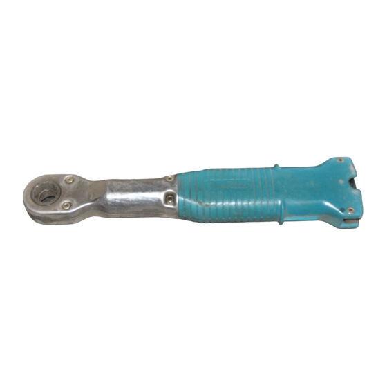
C
ONCEPTION AND MAIN APPLICATIONS
This product was developed to make temporary
fastening of bolts and nuts easier for constructing
prefabricated houses.
It can also be used as an ordinary ratchet wrench to
finally tighten the bolts and nuts by swiveling its
handle clockwise with the ratchet mechanism.
The model 6912DW is made up of
6912D (Makita 12mm battery powered ratchet wrench)
DC7000 (Boosting charger)
The model 6912D does not include batteries.
S
pecifications
Motor
No load speed(R.P.M.)
The size of the eyelet part of the wrench
Bolt size suitable for the model
Temporary fastening with the torque by
Net weight(Kg)
S
tandard equipment
Socket adapter --- One piece.
O
ptional accessories
Battery model 7000
The standard equipment for the tools shown may differ form country to country
6912D
12mm Cordless ratchet wrench
23
DC 7.2 magnet motor
270
21 mm in thickness with two eyelet parts together
1/25 inches
20 kg-cm
0.85
New Tool
322
Advertisement

Related Manuals for Makita 6912D


Summary of Contents for Makita 6912D
- Page 1 The model 6912DW is made up of 6912D (Makita 12mm battery powered ratchet wrench) DC7000 (Boosting charger) The model 6912D does not include batteries. pecifications Motor DC 7.2 magnet motor...
- Page 2 epair 1) Replacement of the clutch (2)Hexagon socket head cap screw Gripping position (1)Hexagon socket head cap screw (4)Sub-housing R (6)Housing R Fig.1 (3)Sub-housing L (5)Housing L (1) Loosen the hexagon socket head cap screws 1 (M4x18) and 2 (M4x25) with hexagon socket screw keys. and dismantle the sub-housing R and L, and housing R and L.
- Page 3 (12) (13) (20) (22) (19) (14) (15) (16) (17) (18) (23) (24) (21) (10) (11) (27) (25) (26) (29) (28) Fig.2 (7)Torsion spring (8)Spring type catch (9)Ratchet holder (10)Socket 21 (11)Pin 4 (12)Ratchet pawl (13)Torsion spring 7 (14)Sleeve 4 (15)Collar (16)Needle bearing 1015 (17)Flat washer (18)Spindle...
- Page 4 Assembling (1) Assemble the parts from 18 to 21. Hold it down Ditch Grease Hold it down (18)Spring Fig.3 (21)Complete clutch cam assembly Put the 19 steel balls 3.5 with the 20 compression spring 2.4 installed between the balls into the 3.6 mm diameter bore at the end of the 18 spindle.
- Page 5 (4) Turn the wrench upside down, and assemble the parts from 7 to 15. (4)Sub-housing R Mount it on the main body. (10)Socket 21 (5)Housing L Assemble the (10) socket 21 by holding it down. (11)Pin 4 One with the longer (7)Torsion spring5 ground part.