Advertisement
Quick Links
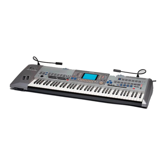
9000 Pro
PROFESSIONAL WORKSTATION
SERVICE MANUAL
CONTENTS
SPECIFICATIONS ..................................................................... 3
WIRING..................................................................................... 5
CIRCUIT BOARD LAYOUT ...................................................... 6
PANEL LAYOUT ...................................................................... 8
DISSASSEMBLY PROCEDURE ............................................. 10
INSTALLING OPTIONAL HARDWARE ................................. 16
LSI PIN DESCRIPTION ........................................................... 24
IC BLOCK DIAGRAM ............................................................. 33
CIRCUIT BOARDS .................................................................. 36
INSPECTIONS & TEST PROGRAM ...................................... 54
MIDI IMPLEMENTATION CHART ......................................... 60
PARTS LIST
BLOCK DIAGRAM
OVERALL CIRCUIT DIAGRAM
This document is printed on chlorine free (ECF) paper with soy ink.
PK
001647
HAMAMATSU, JAPAN
1
1.416K-9112
Printed in Japan '00.10
Advertisement

Related Manuals for Yamaha 9000 Pro


Summary of Contents for Yamaha 9000 Pro
-
Page 1: Table Of Contents
9000 Pro PROFESSIONAL WORKSTATION SERVICE MANUAL CONTENTS SPECIFICATIONS ..............3 WIRING..................5 CIRCUIT BOARD LAYOUT ............6 PANEL LAYOUT ..............8 DISSASSEMBLY PROCEDURE ..........10 INSTALLING OPTIONAL HARDWARE ......... 16 LSI PIN DESCRIPTION ............24 IC BLOCK DIAGRAM ............. 33 CIRCUIT BOARDS .............. - Page 2 IMPOR TANT NOTICE This manual has been provided for the use of authorized Yamaha Retailers and their service personnel. It has been assumed that basic service procedures inherent to the industry, and more specifically Yamaha Products, are already known and under- stood by the users, and have therefore not been restated.
-
Page 3: Specifications
9000 Pro SPECIFICATIONS Keyboard: 76 Keys (E0 ~ G6) Weighted with Touch Response (Initial/After) Polyphony: 126 Notes max Voices: Preset 342 Voices + 480 XG Voices + 24 Drum Kits + 2 SFX Kits Custom User programmable Organ Flute 10 Preset + 10 User, 9 Footages; with Modeling Technology... - Page 4 9000 Pro Registration Memeory: 8 Switches x 64 Banks, Freeze function Language: 5 languages English, German, French, Spanish, Italian Display: Back Lit Graphic LCD 240 x 320 Dots, video out capability Disk: Floppy Disk Drive 3.5" 2HD/2DD Built-in Hard Disk...
-
Page 5: Wiring
9000 Pro WIRING... -
Page 6: Circuit Board Layout
9000 Pro CIRCUIT BOARD LAYOUT Upper Case (Inside View 1) Power Supply Assembly MK-2 Keyboard Assembly AJACK2 AJACK Upper Case (Inside View 2) LCD Assembly... - Page 7 9000 Pro SCSI MIC/HP MIC/VR MK-1 FDD Assembly DJACK Wheel Assembly...
-
Page 8: Panel Layout
9000 Pro PANEL LAYOUT Rear Panel q POWER ON/OFF switch t AUX IN/LOOP RETURN jacks w AC INLET jack (TRIM, R, L/L+R) e LAMP jack y LOOP SEND jacks r LINE OUT jacks (R, L/L+R) u PC KEYBOARD jack MAIN (R, L/L+R) - Page 9 9000 Pro o MIDI A jacks (IN, OUT) !4 LAMP jack !0 MIDI B jacks (IN, OUT) !5 MIC/LINE IN jack !1 HOST SELECT switch !6 PHONES jack !2 TO HOST jack !7 SCSI connector !3 VIDEO OUT jack !8 DIMMER control...
-
Page 10: Dissassembly Procedure
9000 Pro DISASSEMBLY PROCEDURE Bottom Assembly (Time required: About 10 min.) Remove the thirty-one (31) screws marked [300A] inserted, remove the bottom assembly after you and the two (2) screws marked [340]. The bottom disconnect the connectors which connect the 9000Pro assembly can then be removed. - Page 11 9000 Pro <Rear view> [310A] <Bottom view> [170] Power Supply Assembly [320A] x 4 [320D] x 5 [A] x 4 [320B] x 2 SCSI [310B] [320C] x 7 [310A] PW-CB Holder [310B]: Bonding Tapping Screw-B 3.0X8 MFZN2BL (VN413300) [320]: Bind Head Tapping Screw-B 3.0X6 MFZN2Y (EP600130) (Fig.
- Page 12 9000 Pro Power Supply Assembly <Rear view> [80B] [150A] Power Switch <Rear view> INLET Connector Assembly <Top view> [70A] [85] Frame Volume knob (DIMMER) [150B] <Bottom view> [85] [60] [60] MIC/HP Power Supply Unit MIC/VR [60]: Bind Head Tapping Screw-B 3.0X6 MFZN2Y (EP600130) [70A]: Bind Head Tapping Screw-B 4.0X8 MFZN2BL (EG340190)
- Page 13 9000 Pro [750E] x 8 [750D] x 3 LCD Assembly [750B] x 10 [750A] x 6 AJACK2 AJACK DJACK [750C] x 4 [70B] x 4 [800] [750J] x 4 [750G] x 5 [750H] x 18 [750F] x 17 [760] [750I] EN Circuit Board [70B]: Bind Head Tapping Screw-B 3.0 X 6 MFZN2BL (EP600230)
- Page 14 9000 Pro [310C] [310C] Keyboard Support x 3 [320E] [320E] [320E] [300B] Center Angle Bracket [320F] x 5 Keyboard Assembly [300B] [300B]: Bonding Tapping Screw-B 4.0X10 MFZN2BL (VJ254100) [310C]: Bind Head Tapping Screw-B 3.0X8 MFZN2BL (EP600190) [320]: Bind Head Tapping Screw-B 3.0X6 MFZN2Y (EP600130) (Fig.
- Page 15 9000 Pro <Bottom view> FDD Assembly <Right side view> FDD holder R [160] Right side: 2pcs [40] x 4 Left side: 2pcs [160] [90] [160] [40]: Bonding Head Screw 3.0X10 MFNI33 (VK712400) FDD assembly (Fig. 11) [90]: Bind Head Tapping Screw-B 3.0X8 MFZN2BL (EP600190) [160]: Oval Head Screw 3.0X10 (V5115200)
-
Page 16: Installing Optional Hardware
9000 Pro INSTALLING OPTIONAL HARDWARE The following optional units can be installed to the 9000Pro. ¡ Plug-in Boards ¡ Hard disk unit ¡ SIMM Before installing the optional hardware, make sure you have a Philips screwdriver. SIMM cover Plug-in board/Hard disk cover... - Page 17 9000 Pro [A] Optional Plug-in Board Installation The following types of Plug-in boards can be used with the 9000 Pro. • PLG150-AN • PLG150-PF • PLG100-VL • PLG150-VL • PLG100-DX • PLG150-DX • PLG100-XG CAUTION • When inserting Plug-in boards and connecting cables, make sure that you check that they are inserted and connected properly.
- Page 18 9000 Pro Turn over the Plug-in board/Hard disk cover. This is the location for the Hard disk unit. (See page 19.) Plug-in board stand Plug-in board/Hard disk cover Attach the Plug-in Board to the Plug-in board stand......First board -[1] Remove the four screws from the Plug-in stand with a Phillips screwdriver.
- Page 19 9000 Pro Unfasten the cable inside the 9000Pro as shown in the following illus- tration. There are three cables available for installation. The two smaller cables are used for the Plug-in Boards; the larger cable is for the hard disk.
- Page 20 9000 Pro [B] Optional Hard Disk Installation The hard disk used must be a 2.5-inch IDE-compatible; however, not all such drives may be installable. CAUTION • When inserting hard disk unit and connecting cables, make sure that you check that they are inserted and connected properly.