Table of Contents
Advertisement
Quick Links
Download this manual
See also:
User Manual
Advertisement
Table of Contents
Troubleshooting

Related Manuals for NETGEAR ProSafe GS700TS


Summary of Contents for NETGEAR ProSafe GS700TS
- Page 1 GS700TS Series Hardware Installation Guide NETGEAR, Inc. 4500 Great America Parkway Santa Clara, CA 95054 USA 202-10221--01 November 2006 v1.0...
-
Page 2: Statement Of Conditions
In the interest of improving internal design, operational function, and/or reliability, NETGEAR reserves the right to make changes to the products described in this document without notice. NETGEAR does not assume any liability that may occur due to the use or application of the product(s) or circuit layout(s) described herein. - Page 3 EN 55 022 Declaration of Conformance This is to certify that the NETGEAR Smart Gigabit Ethernet Switch with Gigabit Ports is shielded against the generation of radio interference in accordance with the application of Council Directive 89/336/EEC, Article 4a. Conformity is declared by the application of EN 55024 Class A (CISPR 22).
-
Page 4: Customer Support
Internet/World Wide Web NETGEAR maintains a World Wide Web home page that you can access at the uniform resource locator (URL) http:// www.NETGEAR.com. A direct connection to the Internet and a Web browser such as Internet Explorer or Netscape are required. - Page 5 [Swedish] väsentliga egenskapskrav och övriga relevanta bestämmelser som framgår av direktiv 1999/5/EG. Íslenska Hér með lýsir NETGEAR Inc. yfir því að Radiolan er í samræmi við grunnkröfur og aðrar [Icelandic] kröfur, sem gerðar eru í tilskipun 1999/5/EC. Norsk NETGEAR Inc. erklærer herved at utstyret Radiolan er i samsvar med de [Norwegian] grunnleggende krav og øvrige relevante krav i direktiv 1999/5/EF.
- Page 6 GS700TS Smart Switch with Gigaport Ports Tested to Comply with FCC Standards FOR HOME OR OFFICE USE PY306100037 Modifications made to the product, unless expressly approved by NETGEAR, Inc., could void the user's right to operate the equipment. v1.0, November 2006...
-
Page 7: Canadian Department Of Communications Radio Interference Regulations
Canadian Department of Communications Radio Interference Regulations This digital apparatus (GS700TS Smart Switch with Gigaport Ports) does not exceed the Class B limits for radio-noise emissions from digital apparatus as set out in the Radio Interference Regulations of the Canadian Department of Communications. - Page 8 viii v1.0, November 2006...
-
Page 9: Table Of Contents
About This Manual Conventions, Formats and Scope ... xi How to Use This Manual ...xii How to Print this Manual ...xii Chapter 1 Introduction Overview ...1-1 Features ...1-2 Stacking ...1-3 Package Contents ...1-4 Chapter 2 Physical Description GS724TS Front and Back Panel Configuration ...2-1 Front and Back Panels ...2-1 GS748TS Front and Back Panel Configuration ...2-2 Front and Back Panels ...2-2... - Page 10 Step 5: Installing an SFP GBIC Module ...4-4 Step 6: Installing Device as Stack Master ...4-5 Step 7: Applying AC Power ...4-6 Step 8: Managing the Switch through a Web Browser or the PC Utility ...4-7 Appendix A Troubleshooting Basic Troubleshooting ... A-1 Additional Troubleshooting Suggestions ...
-
Page 11: About This Manual
The NETGEAR ® GS700TS Series Hardware Installation Guide describes how to install, configure and troubleshoot the GS700TS Smart Switch with Gigaport Ports. The information in this manual is intended for readers with intermediate computer and Internet skills. Conventions, Formats and Scope The conventions, formats, and scope of this manual are described in the following paragraphs: •... -
Page 12: How To Use This Manual
• button to access the full NETGEAR, Inc. online knowledge base for the product model. • Links to PDF versions of the full manual and individual chapters. - Page 13 – Your computer must have the free Adobe Acrobat reader installed in order to view and print PDF files. The Acrobat reader is available on the Adobe Web site at http://www.adobe.com. – Click the print icon in the upper left of the window. Tip: If your printer supports printing two pages on a single sheet of paper, you can save paper and printer ink by selecting this feature.
- Page 14 GS700TS Series Hardware Installation Guide v1.0, November 2006...
-
Page 15: Introduction
Congratulations on the purchase of the NETGEAR GS700TS Smart Switch with Gigaport Ports. The NETGEAR Smart Switch is a state-of-the-art, high-performance, IEEE-compliant network solution designed for users who require a large number of ports and want the power of Gigabit connectivity to eliminate bottlenecks, boost performance, and increase productivity. -
Page 16: Features
(100 meters) over Category 5 Unshielded Twisted-Pair (UTP) cable, but much longer for fiber connections using SFP GBIC modules. Features The following list identifies the key features of the NETGEAR Smart Switch. • 24/48 RJ-45 10/100/1000M auto sensing Giga switching ports. -
Page 17: Stacking
Standard 1U high, rack mountable 19” chassis. Stacking Stacking provides multiple switch management through a single point as if all stack masters are a single unit. All stack masters are accessed through a single IP address through which the stack is managed. -
Page 18: Package Contents
Slave – Runs a slave version of the Switching Algorithm, which allows the applications running on the master unit to control the resources of the slave unit. Package Contents Figure 1-1 shows the package contents of the NETGEAR Smart Switch. Figure 1-1 Verify that the package contains the following: •... - Page 19 GS700TS Series Hardware Installation Guide If any item is missing or damaged, contact the place of purchase immediately. Introduction v1.0, November 2006...
- Page 20 GS700TS Series Hardware Installation Guide Introduction v1.0, November 2006...
-
Page 21: Physical Description
Device hardware interfaces GS724TS Front and Back Panel Configuration The NETGEAR GS724TS Smart Switch is a 24-Port 10/100/1000 + 4-Port SFP Combo port switch, with each RJ45 ports capable of sensing the line speed and negotiating the operation duplex mode with the link partner automatically. -
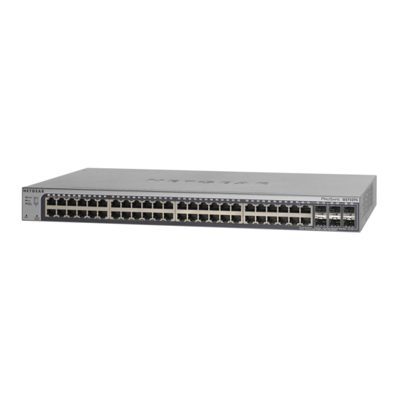
Page 22: Gs748Ts Front And Back Panel Configuration
Two 19 pin HX stacking ports for full-duplex stacking linking. GS748TS Front and Back Panel Configuration The NETGEAR GS748TS Smart Switch is a 48-Port 10/100/1000 + 4-Port SFP Combo port smart stackable switch, with each RJ45 ports capable of sensing the line speed and negotiating the operation duplex mode with the link partner automatically. -
Page 23: Led Designations
Figure 2-4 illustrates the NETGEAR GS748TS Smart Switch back panel: Figure 2-4 The back panel contains the following: • A 100-240VAC/50-60 Hz universal input, which is a standard AC power receptacle for accommodating the supplied power cord. • Two 19 pin HX stacking ports for full-duplex stacking linking. -
Page 24: System Leds
• Green - Displays Stack ID (1-6). • Solid Green - Switch acts as a master unit in a stack of switches. The Stack Master LED is lit if there is an active stack link, and the unit is in stack mode. -
Page 25: Sfp Gbic Module
The GBIC module bays accommodate standard SFP GBIC modules, such as the AGM731F, AGM732F, or AGM733 from NETGEAR, allowing fiber connections on the network. The module bay is a combo port, sharing a connection with an RJ-45 port. Being a combo port, only one type of connection can be active at any given time. - Page 26 GS700TS Series Hardware Installation Guide Physical Description v1.0, November 2006...
-
Page 27: Applications
Desktop Switching The NETGEAR Smart Switch can be used as a desktop switch to build a small network that enables users to have 1000 Mbps access to a file server. With full-duplex enabled, the switch port connected to the server or PC can provide 2000 Mbps throughput. - Page 28 GS700TS Series Hardware Installation Guide Applications v1.0, November 2006...
-
Page 29: Step 1: Preparing The Site
This chapter describes the installation procedures for your NETGEAR Smart Switch. Switch installation involves the following steps: Step 1: Preparing the site Step 2: Installing the switch Step 3: Checking the installation Step 4: Connecting devices to the switch Step 5: Installing an SFP GBIC module... -
Page 30: Step 2: Installing The Switch
Step 2: Installing the Switch The NETGEAR Smart Switch can be installed on a flat surface or in a standard 19-inch rack. Installing the Switch on a Flat Surface The switch ships with four self-adhesive rubber footpads. Stick one rubber footpad on each of the four concave spaces on the bottom of the switch. -
Page 31: Step 3: Checking The Installation
5. Tighten the screws with a #2 Phillips screwdriver to secure the switch in the rack. Figure 4-1 Step 3: Checking the Installation Before applying power perform the following: • Inspect the equipment thoroughly. • Verify that all cables are installed correctly. -
Page 32: Step 4: Connecting Devices To The Switch
Figure 4-2 Connect each PC to an RJ-45 network port on the Switch front panel (see Figure ?4 2). Use Category 5 (Cat5) Unshielded Twisted-Pair (UTP) cable terminated with an RJ-45 connector to make these connections. -
Page 33: Step 6: Installing Device As Stack Master
GS700TS Series Hardware Installation Guide To install an SFP GBIC module: Insert the SFP module into the SFP module bay. Press firmly to ensure the module seats into the connector. Figure 4-3 Step 6: Installing Device as Stack Master The device can operate as part of a stack. The HX stacking ports on the back of the device are used for connecting the devices in a stack.There are two stacking topologies supported by the device, the Ring topology or Chain topology as shown in... -
Page 34: Step 7: Applying Ac Power
For more information on stacking see the NETGEAR Smart Switch User Guide. Step 7: Applying AC Power NETGEAR Smart Switch does not have an ON/OFF switch. The method of applying or removing AC power is by connecting or disconnecting the power cord. Before connecting the power cord, select an AC outlet that is not controlled by a wall switch, which can turn off power to the switch. -
Page 35: Step 8: Managing The Switch Through A Web Browser Or The Pc Utility
Step 8: Managing the Switch through a Web Browser or the PC Utility The NETGEAR Smart Switch contains software for viewing, changing, and monitoring the way it works. This management software is not required for the switch to work. The ports can be used without using the management software. - Page 36 GS700TS Series Hardware Installation Guide Installation v1.0, November 2006...
-
Page 37: Appendix A Troubleshooting
This appendix provides information about troubleshooting the NETGEAR Smart Switch. Topics include the following: • “Basic Troubleshooting” • “Additional Troubleshooting Suggestions” Basic Troubleshooting The following table lists symptoms, causes, and solutions of possible problems. Table A-1. Basic Troubleshooting Symptom Cause Power LED is off. -
Page 38: Additional Troubleshooting Suggestions
AC power from the switch and then reapply AC power. If the problem continues, contact NETGEAR technical support. In North America, call 1-888-NETGEAR. If you are outside of North America, please refer to the support information card included with your product. -
Page 39: Auto-Negotiation
The RJ-45 ports negotiate the correct duplex mode and speed if the device at the other end of the link supports auto negotiation. If the device does not support auto negotiation, the switch only determines the speed correctly and the duplex mode defaults to half-duplex. - Page 40 GS700TS Series Hardware Installation Guide Troubleshooting v1.0, November 2006...
-
Page 41: Technical Specifications
Table B-1. Technical Specifications Network Protocol and Standards Compatibility IEEE 802.3 10BASE-T IEEE 802.3u 100BASE-TX IEEE 802.3ab 1000BASE-T IEEE 802.3ad IEEE 802.3z 1000Base-X IEEE 802.3x flow control IEEE 802.1x IEEE 802.1D Management IEEE 802.1Q Static VLAN (Up to 128 ranging from 2 to 4K) IEEE 802.1p Class of Service (CoS) Port-based QoS (options High/Normal) Port Trunking LACP... - Page 42 GS700TS Series Hardware Installation Guide Table B-1. Technical Specifications Address database size: 8,000 media access control (MAC) addresses per system Mean Time Between Failure (MTBF): 167,355 hours for GS724TS, 125,566 hours for GS748TS Power Supply Power Consumption: 35.1W for GS724TS, 78.36W for GS748TS 100-240VAC/50-60 Hz universal input Physical Specifications Dimensions (H x W x D): GS724TS: 1.7 x 17.32 x 8.07 / 43.2 x 440 x 205 (in/mm), GS748TS: 1.7 x...
-
Page 43: Index
1U 1-3 8-pin 2-4 AC Power 2-2, 2-3 AGM731F 2-5 AGM732F 2-5 AGM733 2-5 Applying AC Power 4-6 Attaching Switch to a Rack 4-3 Auto Sensing 1-2 Auto Uplink 2-4, 2-5 Auto-negotiating 1-3 Auto-select 1-3 Auto-sensing 2-4 Back-pressure 1-3 Backup Master 1-3... - Page 44 IEEE 802.3z 1-3 IEEE Standards 1-2 IEEE-compliant 1-2 Installation Guide 1-4 Installing an SFP GBIC Module 4-4 Installing Device as Stack Master 4-5 Installing the Switch 4-2 Internal Power Supply 1-3 LED Designations 2-3 Link/ACT LED 2-3 Low Latency 1-2 MAC 1-3...
- Page 45 GS700TS Series Hardware Installation Guide Site Requirements 4-1 Web-based Interface 1-3 Slave 1-4 Small Form-factor Pluggable (SFP) 1-2 Smart Switch Resource CD 1-4 Smart Wizard Discovery 1-2 SNMP Management Station 1-3 Stack 1-1 Stack Down LED 2-4 Stack ID LED 2-4...
- Page 46 GS700TS Series Hardware Installation Guide Index-4 v1.0, November 2006...
- Page 47 GS700TS Series Hardware Installation Guide Index-5 v1.0, November 2006...
- Page 48 GS700TS Series Hardware Installation Guide Index-6 v1.0, November 2006...
- Page 49 GS700TS Series Hardware Installation Guide Index-7 v1.0, November 2006...