Table of Contents
Advertisement
Quick Links
Advertisement
Table of Contents

Related Manuals for GE 940


Summary of Contents for GE 940
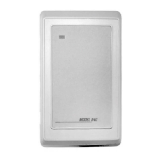
- Page 1 Model 940 Proximity Reader Installation Manual...
- Page 2 GE and the GE monogram are registered trademarks of General Electric. and patents Model 940 Proximity Reader product and logo are trademarks of GE Security. Other trade names used in this document may be trademarks or registered trademarks of the manufacturers or vendors of the respective products.
-
Page 3: Table Of Contents
Contents Introduction ..........1 Safety. - Page 4 Off-the-wall tamper activation..........9 Figure 2. Recommended additional mounting instructions for off-the-wall tamper switch activation9 Figure 3. Model 940 reader - Gang box mounting......10 Figure 4. Model 940 reader - Direct wall mounting......11 Figure 5. Model 940 Reader ...............13 Figure 6.
-
Page 5: Introduction
Introduction Introduction This manual is an installation guide for the GE Model 940 proximity reader which features two-state supervision that continuously monitors for closed and open circuit conditions at door contacts and request to exit (REX) connections. An internal tamper switch automatically alerts security personnel if the reader is violated. -
Page 6: Safety
Model 940 Reader Installation Manual Safety Radio interference WARNING: This is an FCC Class A product. In a domestic environment, this product may cause radio interference, in which case, the user may be required to take adequate measures. Electrostatic discharge (ESD) precaution... -
Page 7: Product Features
12 VDC operation. • A clear, logical user interface with tri-color LED and beeper. • Rugged molded ABS construction with backplate. • Cover removal and off-the-wall tamper detection. 1. The new Model 940 reader (single LED) does not support Proximity Perfect cards. -
Page 8: System Requirements
Model 940 Reader Installation Manual System requirements Host software ® • Secure Perfect Edition 3.0 or later ™ • Picture Perfect 1.7 or later Microcontrollers • Micro/5-PX with 2RP or 8RP • Micro/5-PXN with 2RP or 8RP • M5PXNplus • Micro/PX-2000 •... -
Page 9: Technical Specifications
Technical specifications Technical specifications For UL compliant installation notes, refer to UL listed installations on page 26 Operating temperature -31 F (-35 C) to +150 F (+66 C) range Relative humidity 5% to 95% (non-condensing) Physical dimensions 4.75" (121 mm) x 2.9" (74 mm) x 0.90" (23 mm) (HxWxD) Index of protection IP51... -
Page 10: Parts List
Model 940 Reader Installation Manual Parts list • Model 940 Reader with backplate (gray or black) • Optional installation wrench Refer to the GE price list for part numbers and ordering information. -
Page 11: Installation Overview
Installation overview Installation overview The following steps are general instructions for installing the 940 reader. Each step is explained in further detail in the sections that follow. 1. Mount the reader. Refer to “Mounting the reader” on page 8. 2. Configure the reader Refer to “Configuring the reader”... -
Page 12: Mounting The Reader
Model 940 Reader Installation Manual Mounting the reader The reader comes with a backplate suitable for mounting directly onto standard U.S. electrical gang boxes. The reader may also be mounted directly onto a hollow wall. Important: • Readers should not be mounted within three feet of a computer terminal. -
Page 13: Figure 1. Off-The-Wall Tamper Activation
Mounting the reader Figure 1. Off-the-wall tamper activation To activate the off-the-wall tamper feature, remove the key on the backplate prior to mounting. Figure 2. Recommended additional mounting instructions for off-the-wall tamper switch activation... -
Page 14: Figure 3. Model 940 Reader - Gang Box Mounting
Model 940 Reader Installation Manual Figure 3. Model 940 reader - Gang box mounting... -
Page 15: Figure 4. Model 940 Reader - Direct Wall Mounting
Mounting the reader Figure 4. Model 940 reader - Direct wall mounting... -
Page 16: Configuring The Reader
For unsupervised F/2F or Wiegand 40-bit format output, you must configure the reader using the Reader Configuration Card Kit. Refer to the documentation included in the kit for detailed instructions. The kit can be ordered at no cost from the GE Security price list. -
Page 17: Connect The Reader To The Micro
Connect the reader to the micro Connect the reader to the micro The Model 940 Reader is supplied with a convenient removable 9-pin connector as shown in Figure 5 below. Refer to the following sections for more information on connecting the reader: •... -
Page 18: Pinouts
The table below shows the pinouts for connecting the reader to the microcontroller. Connector J1, pin 1 is to the right as you view the connector from behind the reader. See Figure 5, “Model 940 Reader,” on page 13. Table 1. -
Page 19: Wiring Diagrams
Connect the reader to the micro Wiring diagrams See the following wiring diagrams for details on connecting the reader to the microcontroller: • “Supervised F/2F wiring diagram” on page 16 • “Unsupervised F/2F wiring diagram” on page 18 • “Wiegand wiring diagram” on page 20... -
Page 20: Figure 6. Supervised F/2F Wiring Diagram
Model 940 Reader Installation Manual Figure 6. Supervised F/2F wiring diagram... - Page 21 Connect the reader to the micro...
-
Page 22: Figure 7. Unsupervised F/2F Wiring Diagram
Model 940 Reader Installation Manual Figure 7. Unsupervised F/2F wiring diagram... - Page 23 Connect the reader to the micro...
-
Page 24: Figure 8. Wiegand Wiring Diagram
Model 940 Reader Installation Manual Figure 8. Wiegand wiring diagram... - Page 25 Connect the reader to the micro...
-
Page 26: Testing The Reader
Model 940 Reader Installation Manual Testing the reader Follow the steps below to verify that the reader is working correctly. WARNING: It is important to ensure all connections are made prior to applying power. 1. Check the following: • Proper cabling and electrical connections exist between the reader and the microcontroller. -
Page 27: Indicators
Testing the reader c. Present a card to the reader. Observe that the reader behaves as described in the section “Indicators” on page 23 d. Observe that the green LED turns on, indicating a valid access has been granted by the host. e. -
Page 28: Regulatory Approvals
Model 940 Reader Installation Manual Regulatory approvals Manufacturers Declaration of Conformity Product Identification: 430084001/2 Model/type: Model 940 BOM revision level Category (description): Proximity Reader Brand: GE Security Manufacturer: GE Security Suite 100 791 Park of Commerce Blvd. Boca Raton, Florida 33487 EU Representative: GE Security B.V. -
Page 29: Figure 9. Typical Installation (Internal To The Micro)
Regulatory approvals CE/FCC compliance To make the Model 940 Reader installation CE and FCC compliant, the cable connecting the reader to the micro must have its shield grounded at the micro, according to one of the methods specified in the figures below. - Page 30 Operating Temperature Range: +32 F (+0 C) to +120 F (+49 C) • Relative Humidity: 85% • The Model 940 reader was evaluated by UL for indoor use only. • Request to exit (REX) terminals on the reader are not to be connected for UL listed installations.
- Page 31 NX-8E panel: Connect to the OH2000E Receiver using a dial-up connection. Note: The NX-8E keypad must be installed adjacent to the Model 940 reader in order to be UL compliant. OH2000E Receiver: Connect to the Picture Perfect server, using a serial line RS-232 connection.
- Page 32 Model 940 Reader Installation Manual Notes...
- Page 33 Regulatory approvals Notes...
- Page 34 Model 940 Reader Installation Manual Notes...
- Page 36 Security U.S. T 888 GE SECURITY (1 888 437 3287) F 561 998 6224 Asia T 852 2907 8108 F 852 2142 5063 Australia T 61 3 9259 4700 F 61 3 9259 4799 Europe T 32 2 725 11 20...