Table of Contents
Advertisement
Quick Links
Advertisement
Chapters
Table of Contents

Related Manuals for Jetter JXM-IO-E32


Summary of Contents for Jetter JXM-IO-E32
- Page 1 User Manual JXM-IO-E32 Expansion module 60885294_01 We automate your success.
- Page 2 This document has been compiled by Jetter AG with due diligence based on the state of the art as known to them. Any revisions and technical advancements of our products are not automatically made available in a revised document. Jetter AG shall not be liable for any errors either in form or content, or for any missing updates, as well as for any damage or detriment resulting from such failure.
-
Page 3: Table Of Contents
Requirements for installation location and mounting surface ............ 18 Mounting orientation ........................ 19 5.2.1 Allowed mounting orientations.................. 19 5.2.2 Forbidden mounting orientations ................... 20 Installing the expansion module .................... 21 6 Electrical connection........................ 22 Pin assignment .......................... 24 6.1.1 MOLEX connector ...................... 24 User Manual – JXM-IO-E32... - Page 4 Heartbeat........................ 47 9 Maintenance and repairs........................ 49 Maintenance, repairs and disposal.................... 49 Storage and shipment ....................... 49 10 Service ............................... 50 10.1 Customer service........................ 50 11 Spare parts and accessories ...................... 51 11.1 Accessories .......................... 51 User Manual – JXM-IO-E32...
-
Page 5: Introduction
For information on new revisions of this document, visit the download area on our website. This document is not subject to any updating service. Start | Jetter - We automate your success. For further information refer to the following information products: ■... -
Page 6: Safety
Indicates an imminently hazardous situation which, if not avoided, will result in death or serious injury. WARNING Medium risk Indicates a potentially hazardous situation which, if not avoided, could result in death or serious injury. User Manual – JXM-IO-E32 6 / 55... - Page 7 Indicates a hazardous situation which, if not avoided, could result in minor or moderate injury. NOTICE Material damage Indicates a situation which, if not avoided, could result in mal- functions or material damage. User Manual – JXM-IO-E32 7 / 55...
-
Page 8: Product Description
Product Description | 3 3 Product Description The JXM-IO-E32 is a CAN device with digital inputs for a wide range of pulse measurements and analog inputs for current, voltage and temperature measure- ment. One pin with supply voltage and ground reference is added to each of the 10 analog inputs reducing the cabling effort to a minimum. -
Page 9: Diagnostic Capability Via Leds
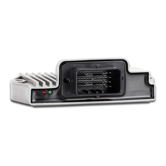
Jetter AG Product Description | 3 3.3 Diagnostic capability via LEDs The JXM-IO-E32 is equipped with 2 LEDs to indicate various states and errors. Color Blinking pattern Description ■ Operating voltage is present (VBAT_ECU). Permanently ON ■ The boot loader is not running. -
Page 10: Nameplate
Product Description | 3 3.4 Nameplate Fig. 2: Sample nameplate Logo Certification mark Registration number and hardware revision Barcode Serial number Model code number 3.5 Scope of delivery Scope of delivery Item number Quantity JXM-IO-E32-G20-K00 10001912 User Manual – JXM-IO-E32 10 / 55... -
Page 11: Technical Specifications
Jetter AG Technical specifications | 4 4 Technical specifications This chapter contains information on electrical and mechanical data as well as operating data of the JXM-IO-E32. 4.1 Dimensions 43.1 38.4 18.6 93.5 Fig. 3: Dimensions in mm INFO CAD data CAD data of the device can be found in the download area of our homepage. -
Page 12: Mechanical Specifications
Salt water resistance The device is not designed for maritime applications. Degree of protection Without mating connector IP23 ISO 20653:2013 with mating connector IP66 Tab. 4: Environmental conditions User Manual – JXM-IO-E32 12 / 55... -
Page 13: Emi Values
Narrowband emission 30 MHz ... 1,000 MHz Min. 1 dB below limit Wideband emission 30 MHz ... 1,000 MHz Min. 1 dB below limit Tab. 7: Emission CISPR 25 ESD EN 61000-4-2 Parameter Values Functional class Contact discharge ±4 kV Discharge through air ±8 kV Tab. 8: ESD EN 61000-4-2 User Manual – JXM-IO-E32 13 / 55... -
Page 14: Outputs
VEXT_SEN is the 24 V output for supplying power to external sensors and is supplied from VBAT_ECU. Abbreviation VEXT_SEN Quantity Operating voltage VBAT Accuracy 1 % Operating current 100 mA Accuracy 1 % Diagnostic function Each channel can be checked for short circuit. Tab. 11: Sensor output VEXT_SEN User Manual – JXM-IO-E32 14 / 55... -
Page 15: Inputs
Within the operating voltage range, all inputs are voltage-proof and overcurrent protected. Alternatively, the analog inputs can also be used as digital inputs (DI). The JXM-IO-E32 has 8 separate VEXT_SEN pins and 2 separate VREF_10V pins that should be used to power the sensors. Each sensor supply is output via a PTC thermistor so that a voltage dip caused by a short circuit can be detected. -
Page 16: Tab. 13 High-Precision Analog Inputs Ai_Prec
VBAT_ECU or GND via an off- set. Parameter Description Configuration inputs for configuring the node ID Abbreviation CFG1 CFG2 Quantity Tab. 15: Configuration inputs CFG1 … CFG2 For more information refer to chapter Setting the node ID [} 36]. User Manual – JXM-IO-E32 16 / 55... -
Page 17: Mechanical Installation
Functional impairment due to magnets or motors with coil Using magnets or motors with a coil in the vicinity of the JXM-IO-E32 may adversely affect current readings of the in- puts and outputs. ► Ensure that there is sufficient clearance or shield the JXM-IO-E32. -
Page 18: Requirements For Installation Location And Mounting Surface
Requirements for ■ Sufficient air circulation the installation ■ Sufficient space between the device and parts that may become very hot space ■ The device must be accessible for service work at all times. User Manual – JXM-IO-E32 18 / 55... -
Page 19: Mounting Orientation
INFO Overheating due to incorrect mounting orientation If the device switches itself off, check whether the device has overheated due to an unfavorable mounting orientation. 5.2.1 Allowed mounting orientations Fig. 4: Allowed mounting orientations User Manual – JXM-IO-E32 19 / 55... -
Page 20: Forbidden Mounting Orientations
Do not route the connector plug vertically upwards. ► Do not use a steam jet near the unprotected device. Any orientation where the connector plug is not protected against splash water or condensation is prohibited. Fig. 5: Forbidden mounting orientation User Manual – JXM-IO-E32 20 / 55... -
Page 21: Installing The Expansion Module
Material Type Quantity Screws/bolts Washers DIN 125-1 Tab. 17: Fastening material Mechanical ► Use both mounting lugs to fasten the JXM-IO-E32. The stud torque is 4 Nm installation max. Fig. 6: Installation drawing User Manual – JXM-IO-E32 21 / 55... -
Page 22: Electrical Connection
Surges may cause malfunctions or damage to the product. ► Protect the voltage inputs from surges according to the re- quirements. ► Ensure that the device is handled in accordance with ESD regulations. User Manual – JXM-IO-E32 22 / 55... - Page 23 Electrical connection | 6 NOTICE Interferences due to differences in potential Differences in potential can lead to interferences. ► Wire sensors and actuators including their supply lines in star configuration to prevent differences in potential. User Manual – JXM-IO-E32 23 / 55...
-
Page 24: Pin Assignment
Reserved pin that must not be connected. NOTICE! Seal unused pins with pin plugs. VBAT_ECU Power supply for logic unit and sensors VEXT_SEN Battery voltage for sensors VREF_10V Stabilized reference voltage for sensors User Manual – JXM-IO-E32 24 / 55... -
Page 25: Tab. 18 Molex Mating Connector - Specification
Manufacturer part number 0643201311 Crimp contacts For 0.75 mm² lines Quantity Manufacturer part number 0643221029 For 1.5 mm² lines Quantity Manufacturer part number 0643231039 Protective cap Manufacturer part number 0643201301 Tab. 18: MOLEX mating connector - Specification User Manual – JXM-IO-E32 25 / 55... -
Page 26: Identification And Configuration
Jetter AG Identification and Configuration | 7 7 Identification and Configuration 7.1 Identification This chapter describes how to identify the JXM-IO-E32 device: ■ Determining the hardware revision ■ Retrieving Electronic Data Sheet (EDS) information. The EDS holds numerous non-volatile production-relevant data. -
Page 27: Electronic Data Sheet (Eds)
Jetter AG Identification and Configuration | 7 7.1.2 Electronic Data Sheet (EDS) Each JXM-IO-E32 features an Electronic Data Sheet (EDS). Production-specific data is stored in the CANopen object indexes 0x4555 and 0x4565. EDS information Types of Index Subindex Description Type... -
Page 28: Os Update Via Jeteasydownload
Identification and Configuration | 7 7.2.1 OS update via JetEasyDownload To update the operating system of this device, use a CAN dongle from PEAK and the Jetter command line tool JetEasyDownload (version 1.00.0.15 or higher). JetEasyDownload To call JetEasyDownload you need specific parameters. - Page 29 The device starts in boot loader mode with a single heartbeat in init state (data = 0x00). Wait for approx. 7 seconds while the device formats the flash memory. ð The device starts the download process. ð The device starts automatically with the new firmware. User Manual – JXM-IO-E32 29 / 55...
-
Page 30: Parameterization
8.1 Concept and control The concept of the JXM-IO-E32 is based on the assignment of interfaces to the inputs and out- puts of the device. Each input and output of the device is called a port and can be configured. -
Page 31: Configuration Options Of Connections
(Overview – I/O interfaces [} 32]). Use the other subindexes to access the parameters, values, and statuses. INFO Assigning Interfaces You can only assign an interface in the Pre-Operational state during the start process. User Manual – JXM-IO-E32 31 / 55... -
Page 32: Tab. 25 Subindexes For Accessing Parameters, Values, And Statuses
I_RATIO ERROR input MIN_DEVIATION OVERVOLTAGE SUPPLY_FAULT (0 V … 12 V) 2 AI_CURRENT SENSOR_SUPPLY I_CURRENT INACTIVE Analog current FILTER_DEEP ERROR input MIN_DEVIATION OVERCURRENT (0 … 24 mA) SUPPLY_FAULT 3 DI_PNP SENSOR_SUPPLY I_DIGITAL INACTIVE Digital input ERROR SUPPLY_FAULT (active-high with pull-down) User Manual – JXM-IO-E32 32 / 55... - Page 33 MIN_TEMPERATURE MAX_TEMPERATURE 20 AO_VOLTAGE FILTER_DEEP I_VOLTAGE INACTIVE (Analog voltage MIN_DEVIATION O_VOLTAGE ERROR output) OVERVOLTAGE 21 AO_CURRENT FILTER_DEEP I_VOLTAGE INACTIVE (Analog current MIN_DEVIATION O_CURRENT ERROR output) OVERVOLTAGE Tab. 26: Available interfaces, parameters, values and statuses User Manual – JXM-IO-E32 33 / 55...
-
Page 34: Tab. 27 Input Values
1 µs I_TEMPERATURE Temperature value °C ... 130 °C Increment 1 °C Tab. 27: Input values Output values Subindex Description Type Value range O_VOLTAGE Voltage value 0 mV … 10,000 mV Increment 1 mV O_CURRENT Set current value 0 µA … 20,000 µA Tab. 28: Output values User Manual – JXM-IO-E32 34 / 55... - Page 35 OVERCURRENT Overcurrent is present at the input/output. 0x00000020 SUPPLY_FAULT The assigned VEXT_xxx channel is faulty 0x00000040 TEMPERATURE- Temperature outside the set range FAULT 0x00000100 TIMEOUT The time (GATE_TIME) for the frequency measurement has been exceeded. Tab. 30: Status User Manual – JXM-IO-E32 35 / 55...
-
Page 36: Setting The Node Id
Jumpered to VBAT → High (H) ■ Open → O The offset corresponds to the values in the following table: CFG1 CFG2 Offset of module ID Tab. 31: Offset for set base node ID User Manual – JXM-IO-E32 36 / 55... -
Page 37: Diagnostic Information
Subindex Description Type Types of access 0x1001 Error register Bit 0 General error Bit 1 Total overcurrent Bit 3 Temperature Bit 4 Communication error Bit 7 CI error (invalid input) Tab. 33: Status information User Manual – JXM-IO-E32 37 / 55... -
Page 38: Saving Settings Permanently And Resetting To Default Values
3. The vehicle controller reads the CRC via index 0x4556, subindex 1 and saves this value locally in a remanent memory. 4. After restarting the JXM-IO-E32, the vehicle controller compares the locally saved CRC value with the value in index 0x4556, subindex 1. If the values do not match, parameteri- zation must be restarted. -
Page 39: System Parameters
*The CRC is calculated using the current parameter values described in chapter Saving settings permanently and resetting to default values [} 38]. INFO Activating the set system parameters You can only use the set system parameters after restarting the system. User Manual – JXM-IO-E32 39 / 55... -
Page 40: Mapping Of Process Data Objects (Pdos)
Event Time U16 R/W 1 ms 10 (10 ms) Tab. 38: RPDO communication parameters INFO Write access to communication parameters Write access to communication parameters is only possible if the JXM-IO-E32 is in the Pre-Operational state. User Manual – JXM-IO-E32 40 / 55... -
Page 41: Tpdo Communication Parameters
Event Time 1 ms 10 (10 ms) Tab. 39: TPDO communication parameters INFO Write access to communication parameters Write access to communication parameters is only possible if the JXM-IO-E32 is in the Pre-Operational state. 8.6.3 Mapping tables RPDO mapping table Types Sub- Index... - Page 42 First object that is mapped 0x1A03 Second object that is mapped … 64. Object to be mapped Tab. 41: TPDO mapping table Mapping entry U32 Byte 2 and 3 Contents Bit length Subindex Index Tab. 42: Mapping entry U32 User Manual – JXM-IO-E32 42 / 55...
-
Page 43: Sending Interface Input Values Via Tpdo
Jetter AG Parameterization | 8 8.6.4 Sending interface input values via TPDO To send interface input values via TPDO, proceed as follows: Switch the JXM-IO-E32 to Pre-Operational state. Assign the desired interface. Invalidate the TxPDO object. Disable the mapping. Enter the mapping value. - Page 44 //Validating object, setting uppermost bit to 0, specifying PDO COB dTemp := 0x180+0x50; CanOpenDownloadSDO( cCanChannel, cJXMNodeId, 0x1800, 1, CANOPEN_DWORD, 4, dTemp, iBusy); when SDOACCESS_FINISHED(iBusy) continue; //Switch JXM-IO-E32 to Operational state CanOpenSetCommand( cCanChannel,CAN_CMD_NMT,CAN_CMD_NMT_Value( cJXMNodeId,CAN_NMT_OPERATIONAL)); User Manual – JXM-IO-E32 44 / 55...
-
Page 45: Frequency Measurement At The Digital Inputs
[mHz] = 10 / (I_HPULSE_TIME + I_LPULSE_TIME) INFO Decrease of resolution In pulse length measurement, the resolution decreases with increasing fre- quency. 8.8 NMT commands The JXM-IO-E32 supports the following NMT commands: NMT commands Description RESET Resets the JXM-IO-E32 PREOPERATIONAL Switches to... -
Page 46: Troubleshooting
Life guard error or heartbeat error 0x8140 Recovered from Bus-Off state 0x8210 Processing errors due to incorrect length of PDOs 0x8220 PDO length exceeded 0xff00 Configuration error on the device 0xff01 I/O-Port OVERVOLTAGE 0xff02 I/O-Port OVERCURRENT User Manual – JXM-IO-E32 46 / 55... -
Page 47: Heartbeat
1 … 4 Node ID to be monitored and timeout Bits 31 … 24 23 … 16 15 … 0 Value Reserved Node ID Heartbeat (Value: timeout 00h) Type Tab. 49: Heartbeat monitoring Value ranges ■ Node ID: 0 … 127 ■ Heartbeat timeout: 0 … 65535 (in ms) User Manual – JXM-IO-E32 47 / 55... - Page 48 ■ = 4 bytes (U32) ■ = reserved ■ = 127 (node ID) ■ = 1000 (timeout in ms) Read first configuration in first entry. r 0x1016 1 Tab. 50: Heartbeat Monitoring - Example User Manual – JXM-IO-E32 48 / 55...
-
Page 49: Maintenance And Repairs
In case of damaged packaging inspect the device for any visible damage, and in- form your freight forwarder and the Jetter AG of the damage caused during ship- ment. If the device is damaged or has been dropped, it is strictly forbidden to use User Manual –... -
Page 50: Service
To contact them, please call our technical hotline or use the contact form on our homepage: Technical hotline | Jetter - We automate your success. You are also welcome to send an e-mail to our technical hotline: hotline@jetter.de... -
Page 51: Spare Parts And Accessories
Only use accessories recommended by Jetter AG. 11.1 Accessories INFO Ordering accessories The accessories are not part of the scope of delivery. Suitable accessories can be obtained from Jetter AG. Accessories Item number Connector set including crimp contacts and blanking 10001729 plugs for individual pins Tab. 51: Accessories... - Page 52 Sample nameplate........................Fig. 3 Dimensions in mm ........................Fig. 4 Allowed mounting orientations....................Fig. 5 Forbidden mounting orientation....................Fig. 6 Installation drawing........................Fig. 7 MOLEX connector ........................Fig. 8 Concept and control ........................ User Manual – JXM-IO-E32 52 / 55...
- Page 53 Tab. 34 Save settings in EEPROM....................... Tab. 35 Resetting the settings to their default values................Tab. 36 System parameters ......................... Tab. 37 Validity of a PDO ........................Tab. 38 RPDO communication parameters..................Tab. 39 TPDO communication parameters ..................User Manual – JXM-IO-E32 53 / 55...
- Page 54 Tab. 46 Subindexes of the error memory ..................... Tab. 47 Emergency Error Codes ......................Tab. 48 Index of the heartbeat message ....................Tab. 49 Heartbeat monitoring ....................... Tab. 50 Heartbeat Monitoring - Example....................Tab. 51 Accessories ..........................User Manual – JXM-IO-E32 54 / 55...
- Page 55 Jetter AG Graeterstrasse 2 71642 Ludwigsburg www.jetter.de E-mail info@jetter.de Phone +49 7141 2550-0 We automate your success.