Pioneer DEH-S5200BT, DEH-S4220BT, DEH-S4200BT Quick Start Guide
- Operation manual (56 pages) ,
- Firmware update instruction (6 pages)
Advertisement
- 1 Before You Start
- 2 Connections
- 3 Installation
- 4 Installing the microphone
- 5 Basic operation
- 6 Setup operation
- 7 Tuner operation
- 8 CD/USB/iPhone/AUX operation
- 9 Bluetooth connection
- 10 Bluetooth telephone
- 11 Making a connection with Pioneer Smart Sync
- 12 Listening to Pandora
- 13 Listening to Spotify
- 14 Documents / Resources
Before You Start
To ensure proper use, please read through this guide before using this product. It is especially important that you read and observe WARNINGS and CAUTIONS in this guide. Please keep the guide in a safe and accessible place for future reference.
FCC ID: EW4C95
MODEL NO.: DEH-S5200BT/DEH-S4220BT/DEH-S4200BT
IC: 4250A-C95
This device contains licence-exempt transmitter(s)/receiver(s) that complies with Part 15 of FCC Rules and Innovation, Science, and Economic Development Canada licence-exempt RSS(s). Operation is subject to the following two conditions:
- this device may not cause interference, and
- this device must accept any interference, including interference that may cause undesired operation of this device.
This transmitter must not be co-located or operated in conjunction with any other antenna or transmitter.
The Bluetooth antenna cannot be removed (or replaced) by user.
This equipment complies with FCC/ISED radiation exposure limits set forth for an uncontrolled environment and meets the FCC radio frequency (RF) Exposure Guidelines and RSS-102 of the ISED radio frequency (RF) Exposure rules. This equipment has very low levels of RF energy that it deemed to comply without maximum permissive exposure evaluation (MPE). But it is desirable that it should be installed and operated keeping the radiator at least 20cm or more away from person's body (excluding extremities: hands, wrists, feet and ankles).
Alteration or modifications carried out without appropriate authorization may invalidate the user's right to operate the equipment.
Note
This equipment has been tested and found to comply with the limits for a Class B digital device, pursuant to Part 15 of the FCC Rules. These limits are designed to provide reasonable protection against harmful interference in a residential installation. This equipment generates, uses and can radiate radio frequency energy and, if not installed and used in accordance with the instructions, may cause harmful interference to radio communications. However, there is no guarantee that interference will not occur in a particular installation. If this equipment does cause harmful interference to radio or television reception, which can be determined by turning the equipment off and on, the user is encouraged to try to correct the interference by one or more of the following measures:
- Reorient or relocate the receiving antenna.
- Increase the separation between the equipment and receiver.
- Connect the equipment into an outlet on a circuit different from that to which the receiver is connected.
- Consult the dealer or an experienced radio/TV technician for help.
FEDERAL COMMUNICATIONS COMMISSION SUPPLIER'S DECLARATION OF CONFORMITY
Product Name: CD RDS RECEIVER
Model Number: DEH-S5200BT/DEH-S4220BT/DEH-S4200BT
Responsible Party Name: PIONEER ELECTRONICS (USA), INC. SERVICE SUPPORT DIVISION Address: 2050 W. 190TH STREET, SUITE 100 TORRANCE, CA 90504, U.S.A.
Phone: 1-310-952-2915
URL: http://www.pioneerelectronics.com
The Safety of Your Ears is in Your Hands
Get the most out of your equipment by playing it at a safe level—a level that lets the sound come through clearly without annoying blaring or distortion and, most importantly, without affecting your sensitive hearing. Sound can be deceiving.
Over time, your hearing "comfort level" adapts to higher volumes of sound, so what sounds "normal" can actually be loud and harmful to your hearing. Guard against this by setting your equipment at a safe level BEFORE your hearing adapts.
ESTABLISH A SAFE LEVEL:
- Set your volume control at a low setting.
- Slowly increase the sound until you can hear it comfortably and clearly, without distortion.
- Once you have established a comfortable sound level, set the dial and leave it there.
BE SURE TO OBSERVE THE FOLLOWING GUIDELINES:
- Do not turn up the volume so high that you can't hear what's around you.
- Use caution or temporarily discontinue use in potentially hazardous situations.
- Do not use headphones while operating a motorized vehicle; the use of headphones may create a traffic hazard and is illegal in many areas.

- Rear visibility systems (backup cameras) are required in certain new vehicles sold in the U.S. and Canada. U.S. regulations began according to a two year phase-in on May 1, 2016, and both the U.S. and Canada require that all such vehicles manufactured on or after May 1, 2018 have rear visibility systems. Owners of vehicles equipped with compliant rear visibility systems should not install or use this product in a way that alters or disables that system. If you are unsure whether your vehicle has a rear visibility system subject to the U.S. or Canadian regulations, please contact the vehicle manufacturer or dealer.
- Do not attempt to install or service this product by yourself. Installation or servicing of this product by persons without training and experience in electronic equipment and automotive accessories may be dangerous and could expose you to the risk of electric shock, injury or other hazards.
- Do not attempt to operate the unit while driving. Make sure to pull off the road and park your vehicle in a safe location before attempting to use the controls on the device.
- This product contains chemicals known to the State of California and other governmental entities to cause cancer and birth defects or other reproductive harm. Wash hands after handling.

- Do not allow this unit to come into contact with moisture and/or liquids. Electrical shock could result. Also, damage to this unit, smoke, and overheating could result from contact with liquids.
- Always keep the volume low enough to hear outside sounds.
- This product is evaluated in moderate and tropical climate condition under the Audio, video and similar electronic apparatus - Safety requirements, IEC 60065.
This product is a Class 1 laser product classified under the safety standard, IEC 60825-1:2014.

USE OF CONTROL OR ADJUSTMENT OR PERFORMANCE OF PROCEDURES OTHER THAN THOSE SPECIFIED HEREIN MAY RESULT IN HAZARDOUS RADIATION EXPOSURE.
THE USE OF OPTICAL INSTRUMENTS WITH THIS PRODUCT WILL INCREASE EYE HAZARD.
After-sales service for Pioneer products
Please contact the dealer, distributor from where you purchased this unit or the authorized PIONEER Service Station for after-sales service or any other information. In case the necessary information is not available, please contact the companies listed below:
Please do not ship your unit to the companies at the addresses listed below for repair without contacting them in advance.
U.S.A. and CANADA
Pioneer Electronics (USA) Inc.
CUSTOMER SUPPORT DIVISION
P.O. Box 1760
Long Beach, CA 90801-1760
800-421-1404
For warranty information please see the Limited Warranty sheet included with this unit.
Connections
- When speaker output is used by 4 channels, use speakers rated over 50 W (maximum input power) and between 4 Ω to 8 Ω (impedance value). Do not use 1 Ω to 3 Ω speakers for this unit.
- When rear speaker output is used by a 2 Ω subwoofer, use speakers rated for over 70 W.
* Please refer to connections for a connection method. - The black cable is ground. When installing this unit or power amp (sold separately), make sure to connect the ground wire first. Ensure that the ground wire is properly connected to metal parts of the car's body. The ground wire of the power amp and the one of this unit or any other device must be connected to the car separately with different screws. If the screw for the ground wire loosens or falls out, it could result in fire, generation of smoke or malfunction.
Two devices connected to the car separately (ground wires)

*1 Not supplied for this unit


- When installing this unit in a vehicle without an ACC (accessory) position on the ignition switch, failure to connect the red cable to the terminal that detects operation of the ignition key may result in battery drain.
![]()
- Use this unit with a 12-volt battery and negative grounding only. Failure to do so may result in a fire or malfunction.
- To prevent a short-circuit, overheating or malfunction, be sure to follow the directions below.
- Disconnect the negative terminal of the battery before installation.
- Secure the wiring with cable clamps or adhesive tape. Wrap adhesive tape around wiring that comes into contact with metal parts to protect the wiring.
- Place all cables away from moving parts, such as the shift lever and seat rails.
- Place all cables away from hot places, such as near the heater outlet.
- Do not connect the yellow cable to the battery by passing it through the hole to the engine compartment.
- Cover any disconnected cable connectors with insulating tape.
- Do not shorten any cables.
- Never cut the insulation of the power cable of this unit in order to share the power with other devices. The current capacity of the cable is limited.
- Use a fuse of the rating prescribed.
- Never wire the negative speaker cable directly to ground.
- Never band together negative cables of multiple speakers.
- When this unit is on, control signals are sent through the blue/white cable. Connect this cable to the system remote control of an external power amp or the vehicle's auto-antenna relay control terminal (max. 300mA 12 V DC). If the vehicle is equipped with a glass antenna, connect it to the antenna booster power supply terminal.
- Never connect the blue/white cable to the power terminal of an external power amp. Also, never connect it to the power terminal of the auto antenna. Doing so may result in battery drain or a malfunction.
- The graphical symbol
![]() placed on the product means direct current.
placed on the product means direct current.

 placed on the product means direct current.
This unit

- Microphone 3 m (9 ft. 10-1/8 in.)
- Power cord input
- Microphone input
- Rear output
- Front output
- Antenna input
- Fuse (10 A)
- Wired remote input
- Hard-wired remote control adapter can be connected (sold separately).
- Subwoofer output
- Rear output or subwoofer output
Power cord
Perform these connections when not connecting a rear speaker lead to a subwoofer.

Perform these connections when using a subwoofer without the optional amplifier.


In the case of  above, two 4 Ω subwoofers wired in parallel will represent a 2 Ω load.
- To power cord input
- Front left speaker
- Front right speaker
- Rear left speaker
- Rear right speaker
- White
- White/black
- Gray
- Gray/black
- Green
- Green/black
- Violet
- Violet/black
- Black (chassis ground)
Connect to a clean, paint-free metal location. - Yellow
Connect to the constant 12 V supply terminal. - Red
Connect to terminal controlled by the ignition switch (12 V DC). - Blue/white
Connect to the system control terminal of the power amp or auto-antenna relay control terminal (max. 300 mA 12 V DC). - Subwoofer (4 Ω)
- When using a subwoofer of 2 Ω, be sure to connect the subwoofer to the violet and violet/black leads of this unit. Do not connect anything to the green and green/ black leads.
- Not used.
- Subwoofer (4 Ω) × 2
- Orange/white (Only for DEH-S5200BT) Connect to a car's illumination signal.
Power amp
(sold separately)
Perform these connections when using the optional amplifier.
DEH-S4220BT/S4200BT

DEH-S5200BT

- System remote control Connect to blue/white cable.
- Power amp (sold separately)
- Connect with RCA cables (sold separately)
- To rear output
- Rear speaker
- To front output
- Front speaker
- To subwoofer output
- Subwoofer
- To rear output or subwoofer output
- Rear speaker or subwoofer
Installation

- Check all connections and systems before final installation.
- Do not use unauthorized parts as this may cause malfunctions.
- Consult your dealer if installation requires drilling of holes or other modifications to the vehicle.
- Do not install this unit where:
- it may interfere with operation of the vehicle.
- it may cause injury to a passenger as a result of a sudden stop.
- Install this unit away from hot places such as near the heater outlet.
- Optimum performance is obtained when the unit is installed at an angle of less than 60°.
![]()
- When installing, to ensure proper heat dispersal when using this unit, make sure you leave ample space behind the rear panel and wrap any loose cables so they are not blocking the vents.


DIN mount installation

- Insert the supplied mounting sleeve into the dashboard.
- Secure the mounting sleeve by using a screwdriver to bend the metal tabs (90°) into place.
- Dashboard
- Mounting sleeve
- Make sure that the unit is installed securely in place. An unstable installation may cause skipping or other malfunctions.
When not using the supplied mounting sleeve
- Determine the appropriate position where the holes on the bracket and the side of the unit match.

- Tighten the screws on each side.

- Screw
- Mounting bracket
- Dashboard or console
- Use either truss (5 mm × 9 mm) or flush surface (5 mm × 9 mm) screws, depending on the bracket screw holes.


Removing the unit (installed with the supplied mounting sleeve)
- Remove the trim ring.

- Trim ring
- Notched tab
- Releasing the front panel allows easier access to the trim ring.
- When reattaching the trim ring, point the side with the notched tab down.
- Insert the supplied extraction keys into both sides of the unit until they click into place.
- Pull the unit out of the dashboard.


To secure the front panel
The front panel can be secured with the supplied screw.

Installing the microphone
The microphone should be placed directly in front of the driver at a suitable distance to pick up their voice clearly.
It is extremely dangerous to allow the microphone lead to become wound around the steering column or shift lever. Be sure to install the microphone in such a way that it will not obstruct driving. It is recommended to use the clamps (sold separately) to arrange the lead.
NOTE
Depending on the vehicle model, the microphone cable length may be too short when you mount the microphone on the sun visor. In such cases, install the microphone on the steering column.
To install on the sun visor
- Fit the microphone lead into the groove.

- Microphone lead
- Groove
- Install the microphone clip on the sun visor.
Lowering the sun visor reduces the voice recognition rate.

- Microphone clip


To install on the steering column
- Slide the microphone base to detach it from the microphone clip.

- Microphone
- Microphone clip
- Microphone base
- Install the microphone on the rear side of the steering column.

- Double-sided tape


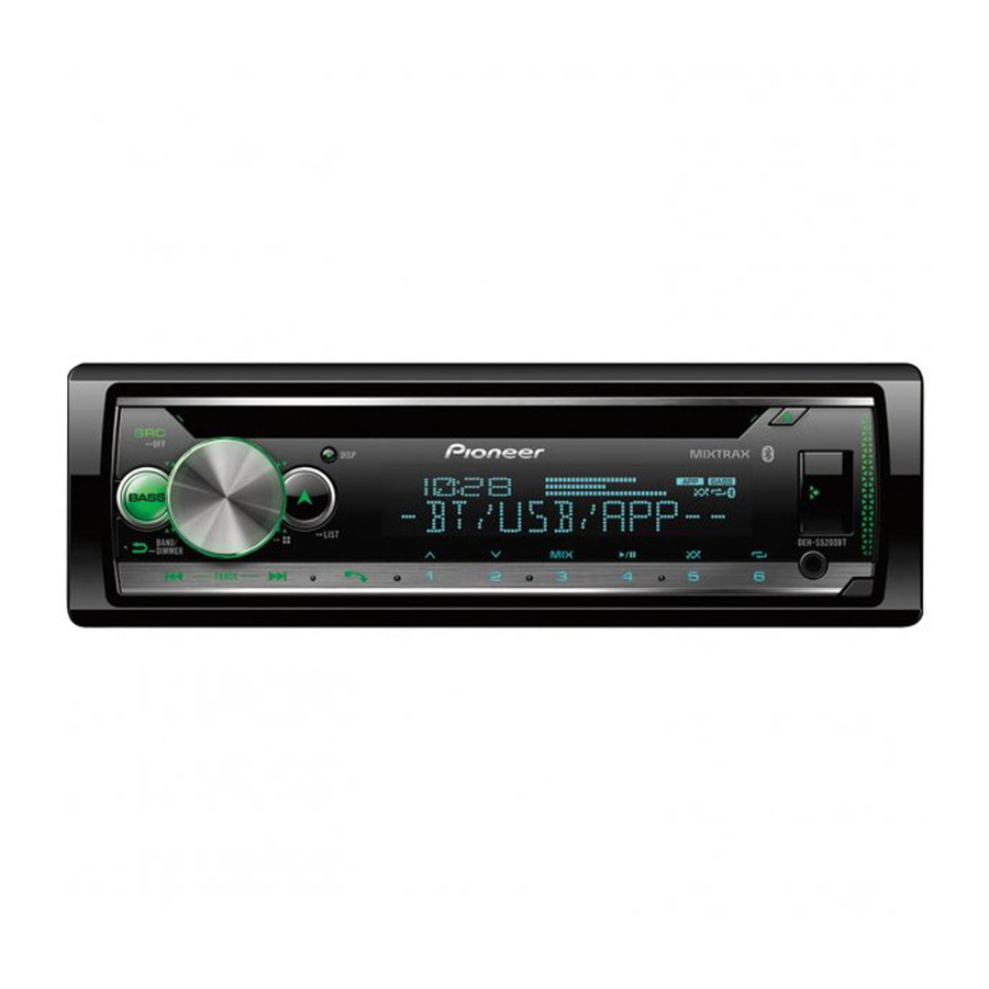
Basic operation
DEH-S5200BT

DEH-S4220BT/S4200BT

About the main menu
You can adjust various settings in the main menu.
- Press the M.C. dial to display the main menu.
- Turn the M.C. dial to select one of the categories below, then press to confirm.
- FUNCTION settings
- AUDIO settings
- SYSTEM settings
- ILLUMINATION settings
- MIXTRAX settings
- Turn the M.C. dial to select the options, then press to confirm.
Frequently used operations
| Purpose | Operation |
| Turn on the power | Press SRC/OFF to turn on the power. Press and hold SRC/OFF to turn off the power. |
| Adjust the volume | Turn the M.C. dial. |
| Select a source | Press SRC/OFF repeatedly. |
| Change the display information | Press DISP repeatedly. |
| Return to the previous display/list | Press BAND/  . . |
| Return to the normal display from the menu | Press and hold BAND/ . |
| Change the display brightness | Press and hold BAND/ . |
| Boost the bass level | Press BASS.
|
Setup operation
When you turn the ignition switch to ON after installation, the setup menu appears in the display.
- Turn the M.C. dial to select [LANGUAGE], then press to confirm.
[ENG]![]() [ESP]
[ESP] ![]() [FRA]
[FRA] - Turn the M.C. dial to select [CLOCK SET], then press to confirm.
- Turn the M.C. dial to adjust the hour, then press to confirm. The indicator moves to the minute setting automatically.
- Turn the M.C. dial to adjust the minute, then press to confirm.
- 3 [QUIT:YES] appears.
To return to the first item of the setup menu, turn the M.C. dial to select [QUIT:NO], then press to confirm. - Press the M.C. dial to confirm the settings.
Tuner operation
Receiving preset stations
- Press SRC/OFF to select [RADIO].
- Press BAND/
![]() to select the band.
to select the band.
[FM1]![]() [FM2]
[FM2] ![]() [FM3]
[FM3] ![]() [AM]
[AM] - 3 Press a number button (1/
![]() to 6/
to 6/ ![]() ).
).
 to select the band.
 [FM2]
[FM2]  to 6/
to 6/ Best stations memory (BSM)
- After selecting the band, press the M.C. dial to display the main menu.
- Turn the M.C. dial to select [FUNCTION], then press to confirm.
- Turn the M.C. dial to select [BSM], then press to confirm.
To store stations manually
- While receiving the station you want to store, press and hold one of the number buttons (1/
![]() to 6/
to 6/![]() ) until it stops flashing.
) until it stops flashing.
CD/USB/iPhone®/AUX operation
(iPhone source is not available when [USB MTP] is set to [ON] in the SYSTEM settings.)
CD
- Insert a disc into the disc loading slot with the label side up.
To eject a disc, stop playback first then press![]() .
.
 .
.USB/iPhone
- Open the USB port cover.
- Plug in the USB device/iPhone using an appropriate cable.
MTP connection
A device installed with Android OS 4.0 or most of later versions can be connected to the unit via MTP, using the cable supplied with the device. However, depending on the connected device, OS version or the numbers of the files in the device, audio files/songs may not be able to be played back via MTP.
NOTE
If you use an MTP connection, [USB MTP] needs to be set to [ON] in the SYSTEM settings.
AUX
- Insert the stereo mini plug into the AUX input jack.
- Press SRC/OFF to select [AUX IN] as the source.
Bluetooth connection
Up to two Bluetooth telephones can be connected simultaneously.
- Turn on the Bluetooth function of the device.
- Select the unit name shown in the device display.
- Make sure the same 6-digit number appears on this unit and the device.
- Select [YES].
Bluetooth telephone
Basic operations
| Purpose | Operation |
| Answer an incoming call | Press any button when a call is received. |
| End a call | Press  . . |
| Reject an incoming call | Press and hold when a call is received. |
Activating voice recognition mode
- Press and hold
![]() and then talk into the microphone to input voice commands.
and then talk into the microphone to input voice commands.
To exit the voice recognition mode, press BAND/![]() .
.
Making a connection with Pioneer Smart Sync
Pioneer Smart Sync is the application that intelligently brings your maps, messages, and music together in the vehicle.


Do not attempt to operate the application while driving. Make sure to pull off the road and park your vehicle in a safe location before attempting to use the controls on the application.
- Enter the SYSTEM menu (refer to "About the main menu").
- Turn the M.C. dial to select [APP CONTROL], then press to confirm.
- Turn the M.C. dial to select one of the below.
- Select [WIRED] for the USB connection.
- Select [BLUETOOTH] for the Bluetooth connection.
- Turn the M.C. dial to select [AUTO APP CONN], then press to confirm.
- Turn the M.C. dial to select [ON], then press to confirm.
- Connect this unit with the mobile device via USB or Bluetooth. Pioneer Smart Sync on the iPhone/Android device starts automatically.
NOTE
Regardless of whether the [AUTO APP CONN] setting is set to [ON] or [OFF], you can also perform the following to start Pioneer Smart Sync.
- For devices other than the USB-connected Android device, press SRC/OFF to select any source and press and hold the M.C. dial.
- For iPhone, launch Pioneer Smart Sync on the mobile device.
Listening to Pandora®
(Not available when [USB MTP] is set to [ON] in the SYSTEM settings.)
Update the firmware of the Pandora application to the latest version before use.
Before you start, connect this unit with the mobile device via USB (iPhone only) or Bluetooth.
- Enter the SYSTEM menu (refer to "About the main menu").
- Turn the M.C. dial to select [APP CONTROL], then press to confirm.
- Turn the M.C. dial to select one of the below.
- Select [WIRED] for the USB connection.
- Select [BLUETOOTH] for the Bluetooth connection.
- Press SRC/OFF to select [PANDORA].
- Launch the Pandora application on the mobile device and start playback.
Listening to Spotify®
(Not available when [USB MTP] is set to [ON] in the SYSTEM settings.)
Update the firmware of the Spotify application to the latest version before use.
Before you start, connect this unit with the mobile device via USB (iPhone only) or Bluetooth.
- Enter the SYSTEM menu (refer to "About the main menu").
- Turn the M.C. dial to select [APP CONTROL], then press to confirm.
- Turn the M.C. dial to select one of the below.
- Select [WIRED] for the USB connection.
- Select [BLUETOOTH] for the Bluetooth connection.
- Press SRC/OFF to select [SPOTIFY].
- Launch the Spotify application on the mobile device and start playback.

(Serial number)
The serial number is located on the bottom of this unit. For your own security and Guide de démarrage rapide convenience, be sure to record this number on the enclosed warranty card.

Documents / Resources
References
![www.pioneerelectronics.com]() Pioneer USA, Car Stereo, Speakers, Home Theater, Navigation, DJ | Pioneer Electronics USA
Pioneer USA, Car Stereo, Speakers, Home Theater, Navigation, DJ | Pioneer Electronics USA![www.apple.com]() App Store - Apple
App Store - Apple![play.google.com]() Google Play
Google Play

Download manual
Here you can download full pdf version of manual, it may contain additional safety instructions, warranty information, FCC rules, etc.
Download Pioneer DEH-S5200BT, DEH-S4220BT, DEH-S4200BT Quick Start Guide
Advertisement
Thank you! Your question has been received!


Need Assistance?
Do you have a question about the DEH-S5200BT that isn't answered in the manual? Leave your question here.