Sony SRG-120DU - HD Color Video Camera Manual
- Operating instructions manual (24 pages) ,
- Technical manual (54 pages)
Advertisement
About the Manuals
Before operating the unit, please read this manual thoroughly and retain it for future reference.
Safety Regulations (supplied)
The Safety Regulations describes the secure usage of camera. Be sure to read it.
Installation Manual (this document)
This Installation Manual describes the names and functions of parts and controls of the camera, gives connection examples and explains how to set up the camera. Be sure to read the Installation Manual before operating.
Operating Instructions/Application Guide (Web)
The Operating Instructions describe how to set up and control the camera. After installing and connecting the camera correctly, operate it by referring to these Operating Instructions.
The guide can be the following URL: https://pro.sony.com/bbsc/ssr/cat-camerasptz/
Location and Function of Part
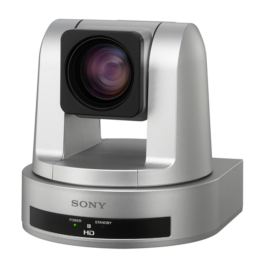
Camera

Front
- Lens
This is a 12-magnification optical zoom lens. - Infrared remote commander sensors
These are sensors for the supplied infrared remote commander. - POWER lamp
The green lamp lights when the camera is connected to an AC outlet using the supplied Sony product; AC adapter MPA-AC1 (hereafter referred to as the AC adapter) and AC power cord. It takes about 15 to 30 seconds to display the image after the lamp lights.
The green lamp flashes when the camera receives an operation command from the supplied infrared remote commander. - STANDBY lamp
The orange lamp lights when the camera is turned off using the infrared remote commander.
Rear
- SYSTEM SELECT switch
Used for selecting the video format of the signal to be output from the USB3.0 connector.
| Switch position | Video format | Switch position | Video format | ||
| 0 | 1920 × 1080p/59.94 | 59.94 Hz system | 8 | 1920 × 1080p/50 | 50 Hz system |
| 1 | No output | 9 | No output | ||
| 2 | 1920 × 1080p/29.97 | A | 1920 × 1080p/25 | ||
| 3 | No output | B | No output | ||
| 4 | 1280 × 720p/59.94 | C | 1280 × 720p/50 | ||
| 5 | 1280 × 720p/29.97 | D | 1280 × 720p/25 | ||
| 6 | No output | – | E | No output | – |
| 7 | VISCA CONTROL | – | F | No output | – |
Notes
- Adjust the refresh rate of the monitor to match the frame rate of the camera.
- Be sure to set this switch before you turn on the power of the camera. You can also set this switch in the standby mode of the camera. After completing the setting, turn on the power of the camera by using any of the following methods: the DC power supply, the VISCA command, or the infrared remote commander.
- Be sure to use a Phillips-head screwdriver when changing the switch position. If you use a tool other than the designated screwdriver, the crossed groove may be damaged.
- If the switch position is set to 1, 3, 6, 9, B, E or F (no output), the POWER lamp and STANDBY lamp will both remain lit. In such cases, control via the infrared remote commander and VISCA commands is disabled.
- If the switch position is set to 7 (VISCA CONTROL), you can configure the video format via external communication.
For detailed information, consult your Sony dealer or Sony Service Center for professional products. - Although the power is turned off temporarily in the VISCA CONTROL mode, the camera is rebooted automatically and the video format is set.
- The set frame rate may not be output depending on the performance and processing condition of a computer.
- VIDEO OUT (USB3.0 video output)
Supplies the images as a USB3.0 video signal.
Note
- Do not apply more than the rated voltage to the USB connector.
- This unit does not have a battery charging function.
- This unit does not support USB2.0 or USB3.1.
- This unit does not support camera control via the USB.
- IR SELECT switch
Select the camera number when you operate multiple cameras with the same infrared remote commander. - VISCA IN connector (mini-DIN 8-pin, female)
Connect to a computer via an RS-232 interface. When you connect multiple cameras, connect it to the VISCA OUT connector of the previous camera in the daisy chain connection.
![]()
Pin No. Function Pin No. Function 1 DTR IN 5 RXD IN 2 DSR IN 6 GND 3 TXD IN 7 IR OUT R* 4 GND 8 IR OUT L* * The IR OUT function of pins 7 and 8 are selectable with the BOTTOM switch on the bottom of the camera.
- VISCA OUT connector (mini DIN 8-pin, female)
When you connect multiple cameras, connect it to the VISCA IN connector of the next camera in the daisy chain connection.
![]()
Pin No. Function Pin No. Function 1 DTR OUT 5 RXD OUT 2 DSR OUT 6 GND 3 TXD OUT 7 No connection 4 GND 8 No connection - LAN connector (RJ-45 8-pin)
Connect a LAN cable that is compatible with 10BASE-T/100BASE-TX (category 5 or higher, shielded twisted pair).
When a link is established, the green indicator lights, and it flashes during communication. While connected with 100BASE-TX, the yellow indicator also lights.


- For safety, do not connect the connector for peripheral device wiring that might have excessive voltage to this port. Follow the instructions for this port.
- When you connect the LAN cable of the unit to peripheral device, use a shielded-type cable to prevent malfunction due to radiation noise.
- DC 12 V (power input) connector
Connect the supplied AC adapter. - Reset switch
The reset switch is available only when LAN is set. If you press this switch with a pointed tip for about five seconds, the camera will reboot and the IP settings will return to the factory default.
Factory settings for IP
IP address: 192.168.0.100
Subnet mask: 255.255.255.0
Name: CAM1
Bottom
- BOTTOM switches
Used for LAN and VISCA CONTROL switching, 9,600 bps and 38,400 bps baud rate selection, and IR signal output setting. To change the setting of the BOTTOM switches, turn off the camera (unless it is in standby mode) first, set the BOTTOM switches, then turn on the camera again. Changing the BOTTOM switches is not possible while the camera is turned on. The default setting of the camera is set to OFF in the factory setting.- VISCA/LAN switch
Select the control setting.
Set to ON to use the LAN connection and set to OFF to use the VISCA CONTROL (RS-232 serial control). - Switch 2 (Not used)
Be sure to set this switch to OFF. - BAUD RATE SELECT switch (when using the serial connection)
Set the communication speed in the VISCA CONTROL.
ON: 38,400 bps OFF: 9,600 bps - IR OUT switch
Set to ON to enable output of the receiver signals, which are transmitted from the infrared remote commander via the VISCA IN connector, or set it to OFF to disable the output. - Switch 5 (Not used)
Be sure to set this switch to OFF. - Switch 6 (Not used)
Be sure to set this switch to OFF. - Switch 7 (Not used)
Be sure to set this switch to OFF. - Switch 8 (Not used)
Be sure to set this switch to OFF.
- VISCA/LAN switch
- Tripod screw hole (1/4-20UNC)
When you use a tripod screw, use this screw hole to fix it. - Mounting screw hole (M3)
Use this hole to secure a bracket, etc. - Rating label
This label shows the name of device and its electric rating.
Infrared Remote Commander (supplied)
")
- CAMERA SELECT buttons
Press the button corresponding to the camera you want to operate with the infrared remote commander. The camera number can be set using the IR SELECT switch (A-![]() ) on the rear of the camera.
) on the rear of the camera.
Note
If two or more cameras are adjacent and have the same camera number, they are operated simultaneously with the same infrared remote commander. When you install the cameras close to each other, set different camera numbers. For the camera number setting, see "Operating Multiple Cameras with the Infrared Remote Commander" in the Operating Instructions. - FOCUS buttons
Used for focus adjustment. Press the AUTO button to adjust the focus automatically. To adjust the focus manually, press the MANUAL button, and adjust it with the FAR and NEAR buttons.
Note
Press the MANUAL button and adjust the focus manually when shooting the following objects.
 ) on the rear of the camera.
- White walls and other objects without contrast
- Objects behind glass
- Objects with horizontal stripes
- Objects on which bright lights are cast or reflected
- Nightscapes and other dark objects with blinking lights
- Lit objects shot with darkened exposure adjustment or exposure compensation settings
- DATA SCREEN button
Press this button to display the main menu. Press it again to turn off the menu. If you press the button when a lower-level menu is selected, the display goes back to a higher-level menu.
Note
Pan/tilt operations are disabled when the menu is displayed (except PAN/TILT LIMIT setting). - PAN-TILT buttons
Press the arrow buttons to adjust the direction of the camera. Press the HOME button to face the camera back to the front.
When the menu is displayed, use![]() or
or ![]() to select the menu items and
to select the menu items and ![]() or
or ![]() to change the set values. The selected setting menu is displayed, by pressing the HOME button when the main menu is displayed.
to change the set values. The selected setting menu is displayed, by pressing the HOME button when the main menu is displayed. - L/R DIRECTION SET button
Hold down this button and press the REV button to change the direction of the camera movement opposite to that indicated by the arrow of the![]() buttons. To reset the direction of the camera movement, press the STD button while holding down this button.
buttons. To reset the direction of the camera movement, press the STD button while holding down this button. - POWER button
Press this button to turn on/off the camera when the camera is connected to an AC outlet. - BACK LIGHT button
Press this button to enable the backlight compensation. Press it again to disable the backlight compensation. - POSITION buttons
Hold down the PRESET button and press button 1 to 6 to store the current camera direction, zooming, focus adjustment and backlight compensation in the memory of the pressed number button.
To erase the memory contents, hold down the RESET button and press button 1 to 6.
Note
These buttons do not function when the menu is displayed. - PAN-TILT RESET button
Press this button to reset the pan/tilt position. - ZOOM buttons
Use the SLOW button to zoom slowly, and the FAST button to zoom quickly. Press the T (telephoto) side of the button to zoom in, and the W (wide angle) side to zoom out.
 or
or  to select the menu items and
  or
or  to change the set values. The selected setting menu is displayed, by pressing the HOME button when the main menu is displayed.
 buttons. To reset the direction of the camera movement, press the STD button while holding down this button.
Installing Batteries in the Infrared Remote Commander

Installing batteries
Two size AA (R6) batteries are supplied for Infrared Remote Commander. To avoid risk of explosion, use size AA (R6) manganese or alkaline batteries.
Danger of explosion if battery is incorrectly replaced.
Replace only with the same or equivalent type recommended by the manufacturer.
When you dispose of the battery, you must obey the law in the relative area or country.
Size AA (R6) batteries not included.
Connections

Check the Videos (Images) of the Camera
When you connect the camera to a computer using the optional USB3.0 cable ( ), you can check the images of the camera.
To check the images, dedicated software (SRGViewer) is needed. For details, refer to the Application Guide.
Notes
- Configure the VIDEO FORMAT, based on the specifications of the computer.
- If the volume of the computer is set to maximum, a sound may emit for a moment when activated, depending on the product. This is not a malfunction.
- It takes about 15 to 30 seconds to display the image.
- To prevent the USB3.0 cable from disconnecting from the camera (either by its own weight or an external force), it is recommended to secure it with commercially available retaining parts, etc.
- Use the optional USB3.0 (Standard-B) cable.
- Depending on the performance capabilities of the USB3.0 cable, some picture noise may occur.
Use an officially-authorized product of Certified SuperSpeed USB (USB3.0) for the USB3.0 cable.
Connecting Multiple Cameras
You can connect multiple cameras using the optional VISCA (RS-232) cable ( ). For detailed information, consult your Sony dealer or Sony Service Center.
Operating the Camera
Notes
- The VISCA connection and the LAN connection do not operate at the same time.
- Use a LAN cable that is compatible with 10BASE-T/100BASE-TX (category 5 or higher, shielded twisted pair) for this connection.
Operating the camera using a computer
You can operate the camera via a computer using the optional VISCA cable ( ) or LAN cable (
 ) instead of the supplied infrared remote commander.
Notes
- To obtain the VISCA cable, consult your Sony dealer. For detailed information on how to connect the camera and the VISCA command list, consult your Sony dealer or Sony Service Center.
- In the case of a VISCA RS-232 connection, make sure that the BOTTOM switch is set to OFF (VISCA (RS-232 serial control)). If VISCA is selected, the camera does not active with a LAN connection.
- In the case of a LAN connection, make sure that the BOTTOM switch is set to ON (LAN). If LAN is selected, the camera does not active with a VISCA connection.
- Dedicated application software is needed.
For details about the application software, consult your Sony dealer. - Use the crossover cable if you want to connect one camera and one PC to the LAN connector directly without using a switching hub.
Operating the camera using the optional IP remote controller (RM-IP10) ( )
)
You can operate the camera from the IP remote controller using the VISCA cable that is supplied to the IP remote controller ( ) or the optional LAN cable (
 ) instead of the supplied infrared remote commander.
For details, see the guide of the setting software - "RM-IP10 Setup Tool" - that is the supplied with the IP remote controller.
Notes
- When you connect the remote controller to the camera by using the VISCA RS-232 connector, set the BOTTOM switch on the bottom of the camera and the remote controller to RS-232. Also, set the same communication speed between the camera and the remote controller.
- In the case of a LAN connection, set the BOTTOM switch on the bottom of the camera and the remote controller to "LAN".
- Use the crossover cable if you want to connect directly to the LAN connector of one camera and one IP remote controller without using a switching hub.
Connecting to an AC Outlet
- Connect the camera to an AC outlet using the supplied AC adapter (d-
![]() ) and power cord (d-
) and power cord (d-![]() ).
).
The power is turned on and the POWER lamp lights.
The camera will automatically pan and tilt and be reset to the position stored in POSITION 1. (Pan/tilt reset action) - Turn on the peripheral devices.
 ) and power cord (d-
 ).
).
This camera does not have a power switch.
When installing the camera, install a circuit breaker in the fixed wiring that is accessible easily, or connect a power plug to an outlet close to the camera to have the power plug removable easily during operation.
When abnormalities occur, turn the circuit breaker off, or unplug it.
Note
The supplied infrared remote commander may not work correctly near the inverter lighting fixtures. In such a case, try to install the camera far from the inverted luminaire.
You can check whether or not the installed location is good for the usage of the infrared remote commander.
For detailed information, consult your Sony dealer or Sony Service Center.
Installation
Installing the Camera on a Desk
Place the camera on a flat surface.
If you have to place the camera on an inclined surface, make sure that the inclination is less than ±15 degrees to guarantee pan/tilt performance, and take measures to prevent it from falling.
Notes
- Do not grasp the camera head when carrying the camera.
- Do not turn the camera head by hand. Doing so may result in a camera malfunction.
Attaching the Camera to a Tripod

Use a screw with a protruding length from the mounting surface ( ) specified in
  for the tripod screw hole and tighten the screw firmly with a screwdriver.
Installation of the camera using the tripod screws and screw holes should not be done for installation on a ceiling or a shelf, etc., in a high position.
Installing the Camera Using the M3 Fixing Screw Holes

Attach the camera using 3 M3 fixing screw holes located on the bottom of the camera. Use the M3 fixing screws with a protruding length from the mounting surface (ℓ) specified in  . Attach the camera to a fitting with a flat surface using the M3 screws and tighten them firmly.
Specifications

System
| Video signal | 1920 × 1080p/59.94 1920 × 1080p/29.97 1280 × 720p/59.94 1280 × 720p/29.97 1920 × 1080p/50 1920 × 1080p/25 1280 × 720p/50 1280 × 720p/25 VISCA CONTROL (switched with the SYSTEM SELECT switch) |
| Synchronization Image device Lens | Internal synchronization 1/2.8 type Exmor CMOS 12× (optical), 12× (digital) f = 3.9 mm (wide) to 46.8 mm (tele) F1.8 to 2.0 Horizontal angle: 71 degrees (WIDE end) |
| Minimum object distance | 10 mm (13/32 inch) (WIDE end) to 1500 mm (591/8 inches) (TELE end) |
| Minimum illumination | 1.8 lux (F1.8, 50 IRE, high-sensitivity mode OFF, 30 fps) 3.6 lux (F1.8, 50 IRE, high-sensitivity mode OFF, 60 fps) 0.4 lux (F1.8, 50 IRE, high-sensitivity mode ON, 30 fps) 0.9 lux (F1.8, 50 IRE, high-sensitivity mode ON, 60 fps) |
| Shutter speed | 1/1 to 1/10000 sec. (22 steps) |
| Video S/N | 50 dB |
| Pan/tilt action | Horizontal: ±100 degrees Maximum panning speed: 300 degrees/sec. Vertical: ±25 degrees M aximum tilting speed: 126 degrees/sec. |
Input/output connectors
| VIDEO OUT | USB3.0 (Standard-B) |
| Control input/output | VISCA IN: Mini DIN 8-pin type, RS-232 VISCA OUT: Mini DIN 8-pin type, RS-232 LAN connector: RJ-45 (8-pin), 10BASE-T/100BASE-TX auto discrimination |
| Power connector | JEITA type4 (DC 12 V) |
General
| Input voltage | 12 V DC (AC adapter 100 to 240 V, 50/60 Hz) |
| Power consumption | 16.8 W |
| Operating temperature | 0 ºC to 40 ºC (32 ºF to 104 ºF) |
| Storage temperature | –20 ºC to +60 ºC (–4 ºF to +140 ºF) |
Dimensions  | Video camera: 153 mm ×156 mm × 153 mm (6 1/8 inches × 61/4 inches × 6 1/8 inches) (w/h/d) Infrared remote commander: 56 mm × 26 mm × 210 mm (2 1/4 inches × 1 1/16 inches × 8 3/8 inches) (w/h/d) |
| Installation angle | Less than ±15 degrees to the horizontal surface |
| Specifications greater than the following are recommended for the computer to be used. | OS: Microsoft Windows 7 (SP1) (32-bit version, 64-bit version), Windows 8.1 (32-bit version, 64-bit version), Windows 10 (32-bit version, 64-bit version) CPU: i5-3210M 2.5 GHz Chipset: Intel(R) 7 Series/c216 Family RAM: 4 GB Host Controller: Intel® USB 3.0 eXHC |
Check if the PC driver is latest one.
To obtain the highest performance, it is recommended to setup a computer with a built-in chipset, not with ExpressCard. The ExpressCard-based USB3.0 host may result in lower performance.
Supplied accessories: AC adapter MPA-AC1 (Sony product) (1), AC power cord (1), Infrared remote commander (1), Safety Regulations (1), Installation Manual (this document) (1 set)
Optional accessories
IP Remote Controller RM-IP10
Note
The supplied AC power cord is used for this camera only. It cannot be used for other cameras.
Design and specifications are subject to change without notice.
© 2015 Sony Corporation
Printed in China

Documents / Resources
References
Download manual
Here you can download full pdf version of manual, it may contain additional safety instructions, warranty information, FCC rules, etc.
Advertisement
Thank you! Your question has been received!


Need Assistance?
Do you have a question about the SRG-120DU that isn't answered in the manual? Leave your question here.