
Related Manuals for Philips 50 T Series


Summary of Contents for Philips 50 T Series
- Page 1 Series 50 T (M1310A) Fetal Telemetry System S E R V I C E G U I D E M1310-9000B Printed in Germany February 2002 Edition 1, A.00.01...
- Page 2 Notice Philips makes no warranty of any kind with regard to this material, including, but not limited to, the implied warranties of merchantability and fitness for a particular purpose. Philips shall not be liable for errors contained herein or for incidental or consequential damages in connection with the furnishing, performance or use of this material.
- Page 3 A caution calls attention to a condition or possible situation that could damage or destroy the product or the user’s work. 2002 Philips Medizinsysteme GmbH All rights are reserved. Reproduction in whole or in part is prohibited without the...
-
Page 5: Table Of Contents
Contents 1.Safety ............1 Safety Symbols . - Page 6 Transmission Range ............23 Transducer Mode Not Detected .
- Page 7 Transmitter Functional Blocks ............69 US Gating .
- Page 8 France ................82 Germany .
- Page 9 List of Figures Figure 1 Troubleshooting: No LED’s Lit on Receiver ....... . .19 Figure 1 Troubleshooting: No LED’s Lit on Receiver (continued from previous page).
- Page 10 List of Figures...
-
Page 11: Safety
Safety Safety Symbols Read this information before setting up, using or servicing your Series 50 T Telemetry System. FCC WARNING This equipment generates, uses and radiates radio-frequency energy, and if it is not installed and used in accordance with this manual, may cause interference to radio communications. -
Page 12: Patient Safety
Patient Safety Patient Safety The Telemetry System should only be used by, or under the direct supervision of, a licensed physician or other health care parctitioner who is trained in the use of fetal heart rate monitors and in the interpretation of fetal heart rate traces. US federal law restricts this device to sale by, or on the order of, a physician. -
Page 13: Protective Earth
Protective Earth Protective Earth To protect hospital personnel and the patient, the cabinet must be grounded. Accordingly, the receiver is equipped with a 3-wire power cable which grounds it to the power line ground when plugged into an appropriate 3-wire receptacle. Do not use a 3-wire to 2-wire adapter with the receiver. -
Page 14: Maximum Input/Output Voltages
Maximum Input/Output Voltages Maximum Input/Output Voltages Receiver (Rear View) Transmitter 1. Service Socket Maximum voltage of ±12V. 2. Socket to Fetal Monitor Maximum voltage of ±12V. 3. Power Input Socket 100-120V ~ or 220-240V ~ 4. Event Marker/Service Socket Maximum Voltage of +5V. 5. -
Page 15: Technical Specifications
Technical Specifications Telemetry System (Receiver and Transmitter) Power Requirements The Telemetry System is set for the correct voltage at the factory, but before you connect power, ensure that the voltage switch is in the correct position for your country. Operating Voltage: 100V - 120V~ or 220V - 240V (±10%). -
Page 16: Controls And Indicators
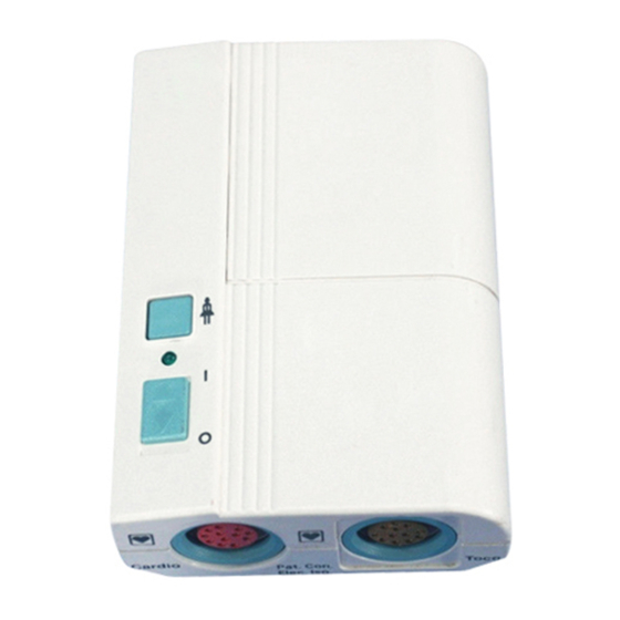
Telemetry System (Receiver and Transmitter) Controls and Indicators Receiver - Controls and Indicators Description Type Color Power On/Off Switch Push Button Power On Light Green Nurse Call Acknowledge/Volume Button Push Button Nurse Call Light Yellow Transmission INOP Light Yellow Battery Low Light Yellow Error Light Transmitter - Controls and Indicators... -
Page 17: Outputs
Telemetry System (Receiver and Transmitter) Transmitter • Cardio socket for M1356A ultrasound transducer or the M1357A/ M1364A DECG transducer. • Toco socket for the M1355A Toco transducer or an IUP Transducer (CPJ840J5). • Remote Event Marker and Service Socket. Outputs Receiver •... -
Page 18: Transducers And Cables
Transducers and Cables Transducers and Cables There are two types of Toco, Ultrasound and DECG Transducers, the Standard Series 50 and Telemetry Transducers. The Standard Transducers have a 2.5m/8ft 2in ventilated cable and the Telemetry Transducers have a 70cm/28in ventilated cable. Both types of Toco and Ultrasound Transducers are colored blue and are watertight complying with IEC 529 (IP68) External Blue Toco Transducers (M1355A) or (M1355A Opt. -
Page 19: Decg Transducer (M1357A)
IUP Quartz Transducer (1290C #J05) DECG Transducer (M1357A) Input Impedance: >10M (di_erential, dc to 50/60Hz). CMRR: >110dB (with patient cable, 51.5k/0.047_F imbalance atline frequency). Noise: <4_Vp (referred to input with 25k). Contact Potential Tolerance:_500mV. Input Voltage Range: 20_Vp to 3mVp. Patient Leakage Current: <10_Arms @ 120V/60Hz. -
Page 20: Iup Pressure Transducer (Cpj840J5)
IUP Quartz Transducer (1290C #J05) IUP Pressure Transducer (CPJ840J5) Pressure range: -20 to + 300 mm Hg Max. overpressure: 10,000 mm Hg µ V/V/mm Hg Sensitivity: Resonance frequency: 300 Hz typical (transducer and dome) Max. electrical excitation: 15 V DC or AC Bridge resistance: 1000 Ohms (input and output) Non-linearity and hysteresis: max. -
Page 21: Tests And Error Messages
Tests and Error Messages Testing the Receiver To run the receiver self test: 1. Switch on the fetal monitor and its recorder. 2. Press the Power On/Off button to switch the receiver on. 3. When you switch on: • The receiver On light (A) comes on. •... -
Page 22: Testing The Transmitter
Testing the Transmitter Testing the Transmitter 1. Slide back the battery cover. 2. Switch on the transmitter. The green On/Off light (A) comes on showing the transmitter is on. 3. Check the red light (B) situated behind the middle battery. If: •... -
Page 23: Testing The Parameter Signals
Testing the Parameter Signals Testing the Parameter Signals The parameter test checks the signal path to and from the transducer sockets, but not the transducers themselves. 1. Switch on the monitor, the recorder and the telemetry receiver. 2. Connect the appropriate transducer to each socket on the transmitter. 3. -
Page 24: Error Messages
Error Messages Error Messages The following error messages are directly related to telemetry and appear on the fetal monitor. Refer to the Instructions for Use provided with your monitor for error messages not related to telemetry monitoring. Series 50 Family Message Display Cause... -
Page 25: 8041A
Error Messages 8041A Message Display Cause Solution Signal Indicator Invalid telemetry mode. Check the cable from the telemetry receiver and, indicator Panel if necessary, replace it. lamps flashing Incorrect transducer Check that the transducer is compatible with connected into Series 50T Fetal Telemetry System. transmitter. - Page 26 Error Messages Chapter 3 - Tests and Error Messages...
-
Page 27: Troubleshooting
Troubleshooting Solving General Problems Troubleshooting is based on the interpretation of the Receiver LED’s. This chapter describes common problems and their causes, and provides troubleshooting flowcharts and guidance for their solution. Problem Possible Causes Solutions All the lights on the Fetal monitor is switched off. - Page 28 Solving General Problems Typical Battery Operating Times at Room Temperature US + TOCO DECG + TOCO DECG + IUP Battery Details 3 x 1.5V Size: AA Type: LR6 Alkaline (1.8 Ah) 180 min 40 hrs 100 min 16 hrs 80 min 14.5 hrs NiCd (0.6 Ah) 10 min...
-
Page 29: No Leds Lit On Receiver (Continued Overleaf)
Solving General Problems No LEDs Lit on Receiver (continued overleaf) Figure 1 Troubleshooting: No LED’s Lit on Receiver Chapter 4 - Troubleshooting... -
Page 30: Figure 1 Troubleshooting: No Led's Lit On Receiver (Continued From Previous Page)
Solving General Problems Figure 1 Troubleshooting: No LED’s Lit on Receiver (continued from previous page) Chapter 4 - Troubleshooting... -
Page 31: Not All Receiver Leds Are Lit
Solving General Problems Not all Receiver LEDs are Lit Figure 2 Troubleshooting Receiver LEDs Yellow LED Remains Lit Figure 3 Troubleshooting: Yellow LED stays on Chapter 4 - Troubleshooting... -
Page 32: Transmission Inop Range
Solving General Problems Transmission INOP Range Figure 4 Troubleshooting: Transmission INOP Chapter 4 - Troubleshooting... -
Page 33: Transmission Range
Solving General Problems Transmission Range Figure 5 Troubleshooting: Transmission Range Chapter 4 - Troubleshooting... -
Page 34: Transducer Mode Not Detected
Solving General Problems Transducer Mode Not Detected Figure 6 Troubleshooting: Transducer not detected Chapter 4 - Troubleshooting... -
Page 35: Cardio Channel
Cardio Channel Cardio Channel Figure 7 Troubleshooting: Cardio Channel Chapter 4 - Troubleshooting... -
Page 36: Toco Channel
TOCO Channel TOCO Channel Figure 8 Troubleshooting: TOCO Channel Chapter 4 - Troubleshooting... -
Page 37: Fmp
Figure 9 Troubleshooting: FMP FMP Test To test an ultrasound transducer: 1. Connect the telemetry receiver to the fetal monitor using the interface cable. 2. Switch on the fetal monitor, its recorder and the telemetry receiver. 3. Connect the transducer to the ultrasound socket. 4. -
Page 38: Figure 10 Fmp Test
6. Apply a small amount of gel on the transducer surface. Holding the transducer in one hand, gently tap the transducer surface with your finger. 7. You should hear a noise from the loudspeaker. Figure 10 FMP Test Chapter 4 - Troubleshooting... -
Page 39: Event Marker
Event Marker Event Marker Figure 11 Troubleshooting: Event Marker Chapter 4 - Troubleshooting... -
Page 40: Nurse Call
Nurse Call Nurse Call Figure 12 Troubleshooting: Nurse Call Chapter 4 - Troubleshooting... -
Page 41: Interfacing To A Fetal Monitor
Interfacing to a Fetal Monitor The Fetal Monitor Interface on the Telemetry Receiver allows digital and analog ouputs to the Monitor. The following table lists the signals at each pin. 6LJQDO 'HWDLOV Not connected. Not connected. Not connected. Not connected. nTELEon Receiver on (L). - Page 42 Chapter 5 - Interfacing to a Fetal Monitor...
-
Page 43: Using The Service Software
Using the Service Software Prerequisites The Service Software runs on IBM-compatible PCs. The latest service software for the M1310A is available from your Medical Response Center. A cable assembly is needed to connect a PC to the Series 50 T Fetal Telemetry System. -
Page 44: Running The Service Software Program
Running the Service Software Program Running the Service Software Program To run the Service Software Program, complete the following: Run tweetsrv.exe You can add /? for HELP how to run /1 for COM1 (default) /2 for COM2 /3 for COM3 /4 for COM4 Example :/tweetsrv.exe /2 The example above runs the program and uses COM2. -
Page 45: Using The Service Program
Using the Service Program Using the Service Program When the program has been loaded onto your PC, the main menu is displayed. (If the menu is not displayed an error message is displayed along the bottom of the screen). Main Menu -------------------------------------------------------------------------------------- --M1310A Service Software Rev.A.xx.xx-- MAIN MENU... - Page 46 Using the Service Program Programs the Serial Number to the Transmitter (if no Serial Number is Program S/N to present on the Transmitter). This feature is needed when the Transmitter Transmitter Printed Circuit Board is exchanged. Follow the steps as the program requests. When moving the service connector from one device to the other, a "SIO RCV error"...
- Page 47 Using the Service Program This feature is only available for HP Service Personnel. It allows you to reset Reset Serial Number the Serial Number on the Transmitter or Receiver Board if the Serial Number was programmed incorrectly.To use this section a Reset-Code from a factory Technical Marketing Engineer is needed.
- Page 48 Using the Service Program Chapter 6 - Using the Service Software...
-
Page 49: Replacing Parts
Ordering Parts To order a part, contact your local Philips Sales/Service Office, quoting the part number listed in the tables. To order a part not listed in the tables, give the following information: •... -
Page 50: Service Tools
Service Tools Service Tools You should have available all the boards and parts listed in the following tables, plus the following tools: • Small crosshead screwdriver. • Medium slothead screwdriver. • Large crosshead screwdriver. • Box screwdriver (HBA). • Spanner (M6 and M5) •... -
Page 51: Figure 13 Transmitter Parts
Lists of Parts Figure 14 Transmitter Parts Chapter 7 - Replacing Parts... -
Page 52: Receiver
Lists of Parts Receiver Receiver Parts List - Boards Item Description Part Number Power Supply Board M1310-69502 Processor Board M1310-69503 Frontpanel Board M1310-66504 Receiver VCXO M1402-61xxx Receiver Board Assembly (Japan) M1310-60305 Receiver Bd Assy. NEW 430-440MHz M1402-60304 Receiver Bd Assy. EXCH 430-440MHz M1402-68304 Receiver Bd Assy. -
Page 53: Figure 14 Receiver Boards
Lists of Parts Figure 15 Receiver Boards Chapter 7 - Replacing Parts... - Page 54 Lists of Parts Receiver Parts List Item Description Part Number Coax Cable Assembly 8120-6413 Flat Cable Assembly (48 pin) 8120-6414 Antenna 450-512 MHz 0950-2028 Antenna 406-450 MHz 0950-2029 BNC-Connector 90 deg. 1250-0076 Power SW Manipulator 5040-9317 Power SW Knob 5040-1203 Receiver Housing Kit M1310-64551 Fuse T300mA/UL...
-
Page 55: Figure 15 Receiver Parts
Lists of Parts Figure 16 Receiver Parts Transducers 'HVFULSWLRQ 3DUW 1XPEHU Toco with 70cm Cable M1355-69013 US with 70cm Cable M1356-69013 DECG with 70cm Cable M1364-60003 Chapter 7 - Replacing Parts... -
Page 56: Dismantling The Transmitter
Dismantling the Transmitter Dismantling the Transmitter 1. Remove the batteries from the battery compartment. 2. Turn the transmitter upside down and, using a small crosshead screwdriver, undo the screw. Removing screw on Transmitter Housing 3. Turn the transmitter over and lift off the top of the transmitter housing. -
Page 57: Transmitter Processor Board
Transmitter Processor Board Transmitter Processor Board To remove the Transmitter Processor Board, follow the instructions for dismantling the transmitter then: 1. Remove the complete assembly from housing by lifting it out from the cardio connector side first. Lifting out Assembly. 2. - Page 58 Transmitter Processor Board 4. Using a small flat bladed screwdriver, carefully prise the VCXO off the board. Do not lean or put excessive pressure upon the board as it contains sensitive components which can be easily damaged. Removing the VCXO 5.
- Page 59 Transmitter Processor Board 7. Replace connector rings to the Cardio and Toco sockets (A). 8. Ensure that the on/off switch manipulator (B) is in the off position. 9. Insert board into housing at an angle, Toco side first. Re-Assembling the Transmitter 10.
-
Page 60: Transmitter Vcxo
Transmitter VCXO Transmitter VCXO To remove the Transmitter VCXO, follow the instructions at the beginning of this chapter for dismantling the Transmitter then: 1. Take out complete assembly from housing by lifting from the cardio side. 2. Lift top board from bottom board by lifting from the cardio side. 3. -
Page 61: Dismantling The Receiver
Dismantling the Receiver 5. Check switch mechanism is set at O (off). 6. Connect the top housing to the bottom housing and snap the two parts together. 7. Screw the housing together carefully (do not press hard). 8. Replace the batteries. 9. - Page 62 Dismantling the Receiver Dismantling the Receiver Note— Cases with spacers are not interchangable with those earlier models that do not have them fitted. Chapter 7 - Replacing Parts...
-
Page 63: Power Supply Board
Power Supply Board Power Supply Board To remove the Power Supply Board, first, follwing the instructions for dismantling the Receiver, then: 1. Remove power switch manipulator (A). 2. Remove flat cable from processor board (B). 3. Remove 7 screws (C). 4. -
Page 64: Processor Board
Power Supply Board 3. Reconnect the ground cable with screw and washer. 4. Reconnect the flat cable from the processor board. 5. Connect power switch manipulator. Processor Board To remove the Processor Board, first follow the instructions for dismantling the Receiver, then: Removing the Processor Board 1. -
Page 65: Rf Module
Power Supply Board Removing the Hexagonal Screws 6. Remove 4 screws. 7. Lift out Processor Board. To replace the Processor Board: 1. Replace the 4 screws which hold the Processor board and tighten them (not completely) so the board can still move. 2. -
Page 66: Receiver Vcxo
Power Supply Board Removing the RF Module Note— Do not forget to remove the RCV-VCXO from the defective Receiver Assembly To replace the RF Module, reverse the above procedure. For details of the RF Bench Repair see Chapter 8. Receiver VCXO 1. -
Page 67: Rf Amplifier
Power Supply Board 3. When fitting the replacement VCXO, angle the new part and locate its pins in one side of the socket. Carefully seat the VCXO, applying gentle pressure until it is securely in position. Fitting the VCXO to RF Module To replace the RF module, reverse the above procedure. -
Page 68: Fuses
Fuses Fuses The fuse values are printed beside the mains socket: For 100-120V Line Voltage T300mA 250V For 220-240V Line Voltage T125 L 250V = alternating current) For part numbers see the Receiver parts list. To replace the fuses: 1. Switch off the Receiver and disconnect it from the main power supply. 2. -
Page 69: Rf Bench Repair
RF Bench Repair Introduction RF Bench Repair should be performed when the low-frequency sections of the Series 50 T Transmitter and Receiver have passed the tests in the Troubleshooting Flowcharts Chapter 4 with no problems. RF associated Transmitter and Receiver problems should be identified and resolved using the RF Bench Test. -
Page 70: Transmitter Vcxo Test
Transmitter VCXO Test Transmitter VCXO Test 1. Open the battery compartment of the Transmitter and remove the batteries. 2. Turn over the transmitter and remove the screw. 3. Pull up the housing top and lift out the Transmitter Board Assembly from the bottom housing. -
Page 71: Figure 17 Fsk Signal
Transmitter VCXO Test Test Point Correct Signal Action If Signal Incorrect +2.5V DC Replace Transmitter Board. +2.5V DC overlayed a sine Replace Transmitter Board. 0.5 to 1Vpp FSK-signal 1.6kHz/2.4kHz. See Figure 18. +5V DC Replace Transmitter Board. 1. Do not forget to program the Serial Number to the Transmitter Board using the Service Software. Without the correct Serial Number the +5V and the FSK signal are not present, as they are switched off. - Page 72 Transmitter VCXO Test Test Point Correct Signal Action if signal incorrect Peak Level >-6dBm Replace Transmitter VCXO Figure 19 RF Output Signal Test Point Correct Signal Action if signal incorrect Peak Level >-12dBm Replace Transmitter Processor board 501 9. Check the modulation. To check the modulation the Spectrum Analyzer should be set as follows: CENTER frequency The channel frequency of the Transmitter...
-
Page 73: Figure 19 Rf Modulation Signal
Transmitter VCXO Test 7HVW 3RLQW &RUUHFW 6LJQDO $FWLRQ LI VLJQDO LQFRUUHFW Seee Figure 20 Replace Transmitter VCXO Figure 20 RF Modulation Signal Chapter 8 - RF Bench Repair... -
Page 74: Receiver Preamplifier Test
Receiver Preamplifier Test Receiver Preamplifier Test 1. Open the Receiver housing. 2. Remove the antenna from the rear BNC connector. 3. Unplug the BNC cable between the Preamplifier and the Receiver assembly at the Preamplifier BNC connector. 4. Switch on the Receiver. The green LED on the Preamplifier Board should be lit. -
Page 75: Receiver Assembly Test
Receiver Assembly Test 7. Using an AC Coupler, connect the Preamplifier’s output to the input of the Spectrum Analyzer. The AC Coupler prevents the Spectrum Analyser input from receiving 21 V DC. The Spectrum Analyser should be set as follows: START frequency 400 MHz STOP frequency... -
Page 76: Receiver Vcxo Test
Receiver VCXO Test 4. Switch on the Receiver. The green LED on the Receiver Assembly should flicker. Check the +5V, -12V and +12V voltages at the marked capacitors. Figure 22 Receiver Assembly Test 5. If all voltages are present and the green LED is flickering now test Receiver VCXO. -
Page 77: Figure 22 Receiver Vcxo Test
Receiver VCXO Test Figure 23 Receiver VCXO Test The Spectrum Analyser should be set as follows: START frequency 400 MHz STOP frequency 500 MHz Resolution Bandwidth 100 kHz Video Bandwidth 100 kHz Reverence Level +10 dBm The Spectrum Analyser measurement must be: Frequency Channel Frequency + 21 .400 MHz +/- 5kHz... - Page 78 Receiver VCXO Test Chapter 8 - RF Bench Repair...
-
Page 79: Theory Of Operation
Theory of Operation Transmitter Functional Blocks US Gating The US Gating circuitry generates the gated 1 MHz bursts for the US driver and the US receiver necessary in a pulsed doppler system. The burst repetition rate is 3.2 kHz. The US driver burst has a duration of µ... -
Page 80: Ecg Driver
Transmitter Functional Blocks demodulator. This demodulator is driven by the US Gating module with 1 MHz bursts. The demodulated signals are amplified and bandpass filtered. The overall gain from the transducer to the US Receiver’s output is 70 dB for the heartrate signal and 56 dB for the fetal movement signal. -
Page 81: Modes
Transmitter Functional Blocks delivered to the FSK Generator. The detector algorithm is identical to the algorithm implemented in the Series 50 Fetal Monitors. FMP is switched off whenever a Series 50 T Telemetry System (plugged into the Monitor) is switched on. FMP is switched back on again when the telemetry system is switched off (or unplugged). -
Page 82: Oscillator
Transmitter Functional Blocks • transducers and operating modes • fetal movement detection bit • battery status • external marker information • Nurse call button • INOP condition of ECG • CRC (checksum over one frame) • Special transmitter ID after power up (Japan only) Oscillator This circuitry produces the different clocks needed in the Transmitter. -
Page 83: Eeprom
Transmitter Functional Blocks EEPROM The EEPROM holds the following settings: • Serial number • Gain calibration factors • Country code • Japanese ID code Japan ID This module is only acitve for Japanese options (set by the country code). It sends the required ID code for Japanese Telemetry Transmitters. -
Page 84: Receiver Functional Blocks
Receiver Functional Blocks Receiver Functional Blocks Input Filter This module builds up a highpass filter with <1dB loss in the useful frequency range 406 to 470 MHz and >20dB rejection for 100 MHz signals. It prevents overloading of the RF preamplifier with strong lower frequency signals. -
Page 85: Rf Receiver M1402A
Receiver Functional Blocks RF Receiver M1402A The MAGIC receiver module M1402A performs the complete baseband signal recovery. The input signal is prefiltered, mixed down and filtered by a double superhetrodyne circuitry and demodulated to the baseband signal. An on board microcontroller does the complete automatic frequency control tracking of the input signal. -
Page 86: Toco D/A Converter
Receiver Functional Blocks • Encode the marker signal into the Toco signal If more than two consecutive frames are disturbed (wrong CRC checksum) or no synchonisation is possible due to not matching serial numbers of the transmitter and the receiver, the output signals are switched off and the range/ transmission INOP LED on the frontpanel is switched on. -
Page 87: Preventive Maintenance, Care And Cleaning
Preventive Maintenance, Care and Cleaning Preventive Maintenance Every 12 months, you must carry out a series of preventive maintenance tasks and performance assurance tests. These ensure that the Telemetry System continues to perform at its best, and reduces the possibility of failures. The tasks to be carried out, their sequence, and the estimated time to complete each one is given in the following table. -
Page 88: Care And Cleaning Of The Telemetry System
Care and Cleaning of the Telemetry System Care and Cleaning of the Telemetry System For care and cleaning instructions, please refer to the Instructions for Use. Chapter 10 - Preventive Maintenance, Care and Cleaning... -
Page 89: Channels And Frequencies
Channels and Frequencies VCXO Operation Frequency The Receiver VCXO operation frequency equals the channel frequency plus 21.4 MHz. Austria M1310A Ref M1402A Channel Transmitter Receiver Option Frequency VCXO-P/N VCXO-PN (MHz) 449.775 M1400-61801 M1402-61801 449.800 M1400-61802 M1402-61802 449.850 M1400-61803 M1402-61803 449.825 M1400-61804 M1402-61804 Australia... -
Page 90: Belgium
Belgium Belgium M1310A Ref M1402A Channel Transmitter Receiver Option Frequency VCXO-P/N VCXO-PN (MHz) 467.775 M1400-61001 M1402-61001 470.025 M1400-61555 M1402-61555 470.050 M1400-61556 M1402-61556 470.075 M1400-61557 M1402-61557 470.100 M1400-61558 M1402-61558 457.525 M1400-61391 M1402-61391 457.600 M1400-61392 M1402-61392 466.2375 M1400-61393 M1402-61393 448.250 M1400-61605 M1402-61605 448.275 M1400-61606 M1402-61606... -
Page 91: Denmark
Denmark M1310A Ref M1402A Channel Transmitter Receiver Option Frequency VCXO-P/N VCXO-PN (MHz) 458.5875 M1400-61704 M1402-61704 458.700 M1400-61705 M1402-61705 458.725 M1400-61706 M1402-61706 458.775 M1400-61707 M1402-61707 458.800 M1400-61708 M1402-61708 Denmark M1310A Ref M1402A Channel Transmitter Receiver Option Frequency VCXO-P/N VCXO-PN (MHz) 448.000 M1400-61601 M1402-61601 448.025... -
Page 92: Eastern European Countries
Eastern European Countries Eastern European Countries M1310A Ref M1402A Channel Transmitter Receiver Option Frequency VCXO-P/N VCXO-PN (MHz) 467.775 M1400-61001 M1402-61001 Finland M1310A Ref M1402A Channel Transmitter Receiver Option Frequency VCXO-P/N VCXO-PN (MHz) 468.525 M1400-61741 M1402-61741 468.575 M1400-61742 M1402-61742 France M1310A Ref M1402A Channel Transmitter... -
Page 93: Germany
Germany M1310A Ref M1402A Channel Transmitter Receiver Option Frequency VCXO-P/N VCXO-PN (MHz) 434.000 M1400-61681 M1402-61681 434.025 M1400-61682 M1402-61682 434.050 M1400-61683 M1402-61683 434.075 M1400-61684 M1402-61684 434.100 M1400-61685 M1402-61685 434.125 M1400-61686 M1402-61686 434.150 M1400-61687 M1402-61687 434.175 M1400-61688 M1402-61688 Germany M1310A Ref M1402A Channel Transmitter Receiver... -
Page 94: Italy
Italy Italy M1310A Ref M1402A Channel Transmitter Receiver Option Frequency VCXO-P/N VCXO-PN (MHz) 430-470 M1400-61xxx M1402-61xxx Japan M1310A Ref M1402A Channel Transmitter Receiver Option Frequency VCXO-P/N VCXO-PN (MHz) J119 440.600 M1400-63119 M1402-63119 J120 440.625 M1400-63120 M1402-63120 J121 440.650 M1400-63121 M1402-63121 J122 440.675 M1400-63122... -
Page 95: Luxembourg
Luxembourg Luxembourg M1310A Ref M1402A Channel Transmitter Receiver Option Frequency VCXO-P/N VCXO-PN (MHz) 467.775 M1400-61001 M1402-61001 470.025 M1400-61555 M1402-61555 470.050 M1400-61556 M1402-61556 470.075 M1400-61557 M1402-61557 470.100 M1400-61558 M1402-61558 457.525 M1400-61391 M1402-61391 457.600 M1400-61392 M1402-61392 466.2375 M1400-61393 M1402-61393 448.250 M1400-61605 M1402-61605 448.275 M1400-61606 M1402-61606... -
Page 96: New Zealand
New Zealand M1310A Ref M1402A Channel Transmitter Receiver Option Frequency VCXO-P/N VCXO-PN (MHz) 434.050 M1400-61683 M1402-61683 434.075 M1400-61684 M1402-61684 434.100 M1400-61685 M1402-61685 434.125 M1400-61686 M1402-61686 434.150 M1400-61687 M1402-61687 434.175 M1400-61688 M1402-61688 New Zealand M1310A Ref M1402A Channel Transmitter Receiver Option Frequency VCXO-P/N VCXO-PN... -
Page 97: Service Usa
Service USA Service USA M1310A Ref M1402A Channel Transmitter Receiver Option Frequency VCXO-P/N VCXO-PN (MHz) 457.525 M1400-61391 M1402-61391 457.600 M1400-61392 M1402-61392 466.2375 M1400-61393 M1402-61393 Singapore M1310A Ref M1402A Channel Transmitter Receiver Option Frequency VCXO-P/N VCXO-PN (MHz) 454.125 M1400-61314 M1402-61313 454.225 M1400-61318 M1402-61318 454.325... -
Page 98: Sweden
Sweden Sweden M1310A Ref M1402A Channel Transmitter Receiver Option Frequency VCXO-P/N VCXO-PN (MHz) 439.750 M1400-61751 M1402-61751 439.775 M1400-61752 M1402-61752 439.800 M1400-61753 M1402-61753 439.825 M1400-61754 M1402-61754 439.850 M1400-61755 M1402-61755 439.875 M1400-61756 M1402-61756 439.950 M1400-61757 M1402-61757 439.975 M1400-61758 M1402-61758 439.900 M1400-61759 M1402-61759 439.925 M1400-61760 M1402-61760... -
Page 99: Usa
M1310A Ref M1402A Channel Transmitter Receiver Option Frequency VCXO-P/N VCXO-PN (MHz) 458.500 M1400-61701 M1402-61701 458.525 M1400-61702 M1402-61702 458.5625 M1400-61703 M1402-61703 458.5875 M1400-61704 M1402-61704 458.700 M1400-61705 M1402-61705 458.725 M1400-61706 M1402-61706 458.775 M1400-61707 M1402-61707 458.800 M1400-61708 M1402-61708 M1310A Ref M1402A Channel Transmitter Receiver Option Frequency... - Page 100 M1310A Ref M1402A Channel Transmitter Receiver Option Frequency VCXO-P/N VCXO-PN (MHz) 466.2625 M1400-62034 M1402-61034 466.3375 M1400-62035 M1402-61035 466.2875 M1400-62036 M1402-61036 468.7625 M1400-62037 M1402-61037 468.8125 M1400-62038 M1402-61038 468.8875 M1400-62039 M1402-61039 468.8375 M1400-62040 M1402-61040 469.0875 M1400-62041 M1402-61041 469.1375 M1400-62042 M1402-61042 469.2125 M1400-62043 M1402-61043 469.1625 M1400-62044...
- Page 101 M1310A Ref M1402A Channel Transmitter Receiver Option Frequency VCXO-P/N VCXO-PN (MHz) 466.2375 M1400-61393 M1402-61393 Chapter 11 - Channels and Frequencies...
- Page 102 Chapter 11 - Channels and Frequencies...
- Page 103 ,QGH[ no LED’s lit on receiver , 19 not all LED's lit , 21 batteries operating nurse call , 30 low warning light environment , 18 Toco channel , 26 operating time temperatures , 17 transducer not detected , 24 bench repair Oscillator transmission INOP range...
- Page 104 Receiver functional blocks transmitter Dynamic Compression , 12 ECG Bandpass service interface Circuitry , 74 , 76 , 70 EEPROM service program ECG Bandpass , 74 , 33 , 75 FSK Bandpass cable assembly ECG Driver , 74 , 33 , 70 check receiver FSK Demodulator...
- Page 105 ultrasound Toco Receiver transmission range , 69 , 23 watertight blue US Driver yellow LED stays on , 69 , 21 Transmitter US Gating , 69 replacement and removal US Receiver , 50 , 69 transmitter VCXO , 69 testing Transmitter processor board , 12 ultrasound transducer...