Table of Contents
Advertisement
Quick Links
Advertisement
Table of Contents

Related Manuals for Oceanic Systems 5700


Summary of Contents for Oceanic Systems 5700
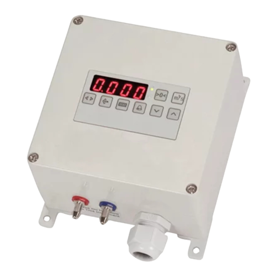
- Page 1 Air Volume Monitor Part Numbers: 5700 USER MANUAL Document revision 1.00...
-
Page 2: Table Of Contents
CONTENTS 1. OVERVIEW 1.1 FRONT PANEL LAYOUT 1.2 DIAGNOSTIC LEDs 2.DIMENTIONS & CONNECTIONS 2.1 3 & 4 WIRE CONNECTIONS 3. CONFIGURATION 2.1 ACCESSING MENUS 2.2 RANGE KEY PARAMETERS 2.3 OUTPUT KEY - PARAMETERS 2.4 DISPLAY KEY - PARAMETERS 2.5 ALARM KEY PARAMETERS 4. -
Page 3: Overview
OVERVIEW These sensors are wall, or panel backplate, mount air pressure / velocity sensors that provides an output signal of 0-10V and 4-20mA. The units also features MODBUS communication and an adjustable alarm relay output. The red LED display shows the actual pressure or velocity/volume in the selected units depending on the settings. -
Page 4: Diagnostic Leds
1.2 DIAGNOSTIC LEDs The red and green LEDs on the keyboard as well as the right hand decimal point on the display indicate various conditions as shown below. Green LED ON Normal operation Red LED OFF Green LED OFF Alarm condition – see alarm section Red LED ON The display is temporarily showing an alter- Both LEDs flashing together... - Page 5 DIMENTIONS & CONNECTORS...
-
Page 6: Wire Connections
2.1 3 & 4 WIRE CONNECTIONS... -
Page 7: Configuration
2.0 CONFIGURATION 3.1 ACCESSING MENUS There are menus under the following keys: (Output) (Range) (Display) (Alarm) > < (Control) Pressed together. To access a menu, hold down the key until the LED display changes (approx 1 second). The display will now show a parameter and its value. The same menu key is then used to step through all the available parameters within the menu. -
Page 8: Range Key
3.2 RANGE KEY PARAMETERS Note: A short press on this key will display the Full Scale Range of the sensor in the selected display units. Sensors with a -/+ range will show Pn indicating that the P and n parameters both need to be checked to see the range. - Page 9 Negative Range This is the Negative Range of the sensor and is displayed in Pascals (Pa). This range can be adjusted within certain limits (Consult CMR). Over-Pressure Protection When set to 1 (ON), the internal electronic air valve will remove air pressure from the sensor when an over-pressure condition is detected.
- Page 10 Internal / External Controls When set to ‘I’ (Internal), then the network address, range, output smoothing, output mode, small value shut off, mag factor and alarm threshold are set by the internal controls. The values will be viewable on the display but cannot be changed by the keyboard. If set to ‘E’...
-
Page 11: Output Key
3.3 OUTPUT KEY PARAMETERS Note: Under normal operation a short press on this key will display either Lin or Root, indicating the output mode. If PID control mode is set then this key instead switches the display to show the current percentage value of the control output for a few seconds. - Page 12 If set to ‘L’ (Direct Entry Method), then the sensor uses a look up table to convert the differential pressure to velocity or volume. The look up table can have from 1 to 8 points. Each point consists of a pressure and an associated velocity or volume figure. If the look up table only has 1 point then the output from the sensor will be linear against square rooted pressure.
- Page 13 is not linear and has for example a volume of 1.700 m3/s at 50Pa, then another Lin point can be added to correct for this error. 1. Follow the single point example until the display shows Lin.0 (Note that the decimal point in front of the 0 is lit, showing that Lin 0 is already set up).
- Page 14 Mag Factor (F Parameter) E parameter is set to F. This will set the desired Magnification Factor of the measurement device. Measured pessure (Pa) is divided by this value. Eg: Typically Oval Flowprobes = Mag 1.5 (150Pa / 1.5 = 100Pa) K Factor –...
- Page 15 The output scaling can be changed by adjusting the parameter on the menu. If this value is 0 then it is ignored, and the full scale output of the sensor will be the value shown when the key is pressed. If for example the value shown when pressing the key is 2.000 m3/s and a value of 4.000m3/s for at 10V/20mA is preferred then the o parameter could be changed to 4.000.
-
Page 16: Display Key
3.4 DISPLAY KEY PARAMETERS Note: A short press on this key will display the displayed units. These are shown as indicated below. INDICATOR PARAMETER RANGE Display Smoothing 0-99 Display Units: Pascals hecta Pascals (mbar) kilo Pascals metres per second n n PS litres per second cubic metres per second n n3S... - Page 17 nipple, the output signal will be between 0 and 10V for 0 to 1000Pa. The display can be made to read 0 to -1000Pa by setting the display polarity to negative. If PID control is being used and the display polarity is set to negative then the setpoint is also negated internally.
-
Page 18: Alarm Key
3.5 ALARM KEY PARAMETERS INDICATOR PARAMETER RANGE Low Alarm High Alarm Alarm Timer 1 0-999 seconds Alarm Timer 2 0-999 seconds Relay Energization Units Alarm Function 0 - 3 Self Reset 0 or 1 Alarm Reset b o r rb Buzzer Function 0 –... - Page 19 Alarm Timer 1 & 2 Alarm delays in seconds. See Alarm Function below. Relay Energization The relay is normally de-energized and will energize when in alarm. The relay is normally energized and will drop out when in alarm. The front panel LED is red when in alarm regardless of the relay energization.
- Page 20 Alarm Function MODBUS SET ALARM The sensor does not generate any alarms in alarm mode zero. The alarm relay, the internal buzzer and the remote display alarm are driven directly via MODBUS. See MODBUS communications specification. INTERNALLY SET ALARM This is only used for applications where the keyboard and display are not fitted. The alarm pot on the PCB sets a threshold as a percentage of the full scale range of the sensor.
-
Page 21: Alarm Test Mode
ALARM TEST MODE To activate the Alarm Test Mode, hold down the keys simultaneously until the display shows tESt. The internal relay will be switched on and off at 1 second intervals until the is pressed. If this test mode is not manually cancelled by pressing the key then it will automatically stop after a period of 15 minutes. -
Page 22: Calibration Mode
NEW PASSWORD ENTRY If a password already exists, this will have to be entered before a new password can be entered. Hold down both the Range Key and Up Key simultaneously for 1 second. The display will read 1_ _ _ _ , enter a 4 digit password. The display will read 2_ _ _ _ , enter the same 4 digit password. -
Page 23: Output Range Configuration
7.1 OUTPUT RANGE CONFIGURATION Output key - Calibration Mode INDICATOR PARAMETER RANGE Minimum Output Voltage 0-10 (e.g.0V) Maximum Output Voltage 0-10 (e.g.10V) Minimum Output Current 0-20 (e.g.4mA) Maximum Output Current I ¯ 0-20 (e.g.20mA) Calibration mode output 0 or 1 freeze Note: Calibration mode will exit automatically when this menu is exited. -
Page 24: Calibration Mode Output Freeze
Press the Range key to finish. The sensor will return to its normal operation ending the calibration mode. The right hand decimal point will stop flashing. 7.3 CALIBRATION MODE OUTPUT FREEZE If the OPF parameter is set to 1, the voltage and current outputs will be held at their values prior to entering calibration mode. - Page 25 HAND SETPOINT In hand mode, the control output will be fixed at this value. The value is between 0.0 and 99.9% of full scale output. e.g. with a 50.0% setpoint the output will be 5V on the 0-10V voltage output or 12mA on the 4-20mA output. keys are used to change the setpoint.
-
Page 26: Remote Display
DIRECTION P=The output voltage increases if the input is below setpoint. n= The output voltage decreases if the input is below setpoint. REMOTE DISPLAY A remote display can be connected to terminals 7 – 10 on the sensor. The remote display replicates the value shown on the instrument display when the instrument is in normal operation. -
Page 27: Communications
OPERATING MODE This must be set to SEn to configure the display as a remote display for the PV-210, V-SENSOR and VP-SENSOR BUZZER & ALARM INDICATION The buzzer and alarm indication functions on the remote display can be set on the sensor or they can be set on the remote display. - Page 28 Available registers Description Data Read/ Function 1 based Type Write Code 40138 Low alarm threshold See “alarm thresholds” 0x03 read below for data type and 0x06 scaling write 40139 High alarm threshold 0x03 read 0x06 write 40140 Alarm timer 1 In seconds if timer units 0x03 read are in seconds or 0.1h if...
- Page 29 40151 Pascals real The measured pressure 0x03 40152 as a floating point value. 40153 Control setpoint real The setpoint for the 0x03 read 40154 PID control loop. If PID 0x10 control is not being write used then the PID setpoint can be set to a value by the keyboard and read back here e.g.
-
Page 30: Specifications
Float Format Storage method Registers Parameter 40149 40150 Little Endian 0x79E9 0xF642 Little Endian, with bytes swapped 0xE979 0x42F6 Big Endian 0x42F6 0xE979 Big Endian, with bytes swapped 0xF642 0x79E9 ALARM THRESHOLDS The alarm thresholds are unsigned 16 bits values with the zero offset to 32768. This is not the same as a signed 16 bit integer. - Page 31 Power consumption 24Vdc Maximum 90mA or 120mA with remote display. 24Vac Maximum 165mA or 195mA with remote display. 110Vac Maximum 40mA. 230Vac Maximum 20mA. Voltage Output 0-10V (0 to100% of Range) RL = 5kOhm min. Signal Other output signals (e.g. 2-10V) programmable via front keyboard. Output may be configured as a control output.
- Page 32 SPECIFICATIONS CONTINUED Enclosure Plastic (ABS) Light Grey (RAL7035) - Protection IP65. Optional Die-cast Aluminium Light Grey (RAL7035) - Protection IP65. Dimensions & ABS Housing: weights Height 146mm (Including Width 122mm mounting feet) Depth 80mm Weight 0.7kg Aluminium Housing: Height 120mm Width 145mm Depth...
- Page 33 Systems sole obligation hereunder, provided product is returned pursuant to the return requirements below, shall be limited to the repair or replacement, at Oceanic Systems option, of any product not meeting the above limited warranty and which is returned to Oceanic Systems; or if Oceanic Systems is unable to deliver a replacement that is free from defects in materials or workmanship, Purchaser’s...
- Page 34 Email: sales@osukl.com Web: www.osukl.com Copyright © 2019 Oceanic Systems(UK) Ltd. All rights reserved. Our policy is one of continuous product improvement so product specifications are subject to change without notice. Oceanic Systems products are designed to be accurate and reliable. However, they should be used only as aids to vessel monitoring, and not as a replacement for traditional navigation and vessel monitoring techniques.