
Related Manuals for GE 12R II Series


Summary of Contents for GE 12R II Series
- Page 1 COE Communications Engineering Document Author: Rev: Keith Gilbertson TRANSPORTATION SYSTEMS Date: 3/08/02 Title: GLOBAL SIGNALING DIVISION 12RII FCC TECHNICAL MANUAL...
-
Page 2: Table Of Contents
COE Communications Engineering Document Author: Rev: Keith Gilbertson TRANSPORTATION SYSTEMS Date: 3/08/02 Title: GLOBAL SIGNALING DIVISION 12RII FCC TECHNICAL MANUAL TABLE OF CONTENTS Scope..................................... 3 Revision History ................................... 3 Reference Documents ................................3 Abbreviations and Acronyms ..............................3 12RII Radio Systems ................................ -
Page 3: Scope
COE Communications Engineering Document Author: Rev: Keith Gilbertson TRANSPORTATION SYSTEMS Date: 3/08/02 Title: GLOBAL SIGNALING DIVISION 12RII FCC TECHNICAL MANUAL Scope This document provides the necessary technical information to comply with the requirements for FCC certification. This document will be superseded by the 12RII Service Manual when issued. Revision History DATE COMMENTS... -
Page 4: Rii Radio Systems
COE Communications Engineering Document Author: Rev: Keith Gilbertson TRANSPORTATION SYSTEMS Date: 3/08/02 Title: GLOBAL SIGNALING DIVISION 12RII FCC TECHNICAL MANUAL 12RII Radio Systems The 12RII radio supports 3 major types of FM voice radio systems or applications. AAR Remote Control (RC), Locomotive Clean Cab (LC) and Serial Remote (SR). - Page 5 COE Communications Engineering Document Author: Rev: Keith Gilbertson TRANSPORTATION SYSTEMS Date: 3/08/02 Title: GLOBAL SIGNALING DIVISION 12RII FCC TECHNICAL MANUAL 5.1.2. AAR Remote Radio System Block Diagram Handset Antenna 12RII-RC Cab Controls AAR Remote Audio Interfaces Radio System Battery 5.1.3. Basic Operation The AAR Remote Radio is capable of performing all standard radio functions associated with transmitting and receiving radio signals.
-
Page 6: Clean Cab Radio Systems
COE Communications Engineering Document Author: Rev: Keith Gilbertson TRANSPORTATION SYSTEMS Date: 3/08/02 Title: GLOBAL SIGNALING DIVISION 12RII FCC TECHNICAL MANUAL 5.2. Clean Cab Radio systems 5.2.1. General Description The 12RII-LC radio is compatible with the current 12R-LC radio in all its existing clean cab Applications. Refer to the block diagram in the following section. - Page 7 COE Communications Engineering Document Author: Rev: Keith Gilbertson TRANSPORTATION SYSTEMS Date: 3/08/02 Title: GLOBAL SIGNALING DIVISION 12RII FCC TECHNICAL MANUAL signaling. Audio interfaces on the front panel include a front panel microphone, which is activated with the front panel PTT button, and a radio speaker.
-
Page 8: Serial Remote Radio Systems (Future Option)
COE Communications Engineering Document Author: Rev: Keith Gilbertson TRANSPORTATION SYSTEMS Date: 3/08/02 Title: GLOBAL SIGNALING DIVISION 12RII FCC TECHNICAL MANUAL 5.3. Serial Remote Radio Systems (Future Option) 5.3.1. General Description The standard 12RII-SR radio is identical in operation to the 12RII-LC radio except that it is not mounted in the typical brake stand enclosure. -
Page 9: Radio Front Assembly Parts List (Lc Version Only)
COE Communications Engineering Document Author: Rev: Keith Gilbertson TRANSPORTATION SYSTEMS Date: 3/08/02 Title: GLOBAL SIGNALING DIVISION 12RII FCC TECHNICAL MANUAL 251303-1100 ASSY 12RII-RC 36V VHF GSPN DESCRIPTION 017157-402 PWR SPLY VICOR 74V 017157-401 PWR SPLY VICOR 36V 227409-000 ASSY POWER SUPPLY BOARD 74V 227409-001 ASSY POWER SUPPLY BOARD 36V 180381-790... - Page 10 COE Communications Engineering Document Author: Rev: Keith Gilbertson TRANSPORTATION SYSTEMS Date: 3/08/02 Title: GLOBAL SIGNALING DIVISION 12RII FCC TECHNICAL MANUAL GSPN DESCRIPTION REF DES / DIN 227410-100 ASSY 12RII FRONT PANEL BOARD 202926-000 ASSY 12RII PROCESSOR MODULE 022207-100 Keypad Left 022207-200 Keypad Numeric 022207-300...
-
Page 11: Radio Architecture
COE Communications Engineering Document Author: Rev: Keith Gilbertson TRANSPORTATION SYSTEMS Date: 3/08/02 Title: GLOBAL SIGNALING DIVISION 12RII FCC TECHNICAL MANUAL Radio Architecture The radio and control head architecture is depicted in the following block diagrams for each of the radio applications. The radio deck in all applications is built around a common chassis. -
Page 12: Rc Radio Block Diagram
COE Communications Engineering Document Author: Rev: Keith Gilbertson TRANSPORTATION SYSTEMS Date: 3/08/02 Title: GLOBAL SIGNALING DIVISION 12RII FCC TECHNICAL MANUAL 6.1. RC Radio Block Diagram HANDSET ANTENNA TXRX RFPA CN203 CN104 P1-P4 J1-J4 CN201 CN202 POWER & CONTROL RADIO CONTROL BOARD RADIO PROCESSOR MODULE... -
Page 13: Lc Radio Block Diagram
COE Communications Engineering Document Author: Rev: Keith Gilbertson TRANSPORTATION SYSTEMS Date: 3/08/02 Title: GLOBAL SIGNALING DIVISION 12RII FCC TECHNICAL MANUAL 6.2. LC Radio Block Diagram HANDSET ANTENNA TXRX RFPA CN203 CN104 POWER P1-P4 J1-J4 CN201 CN202 RADIO CONTROL BOARD ACCESSORY (option) RADIO PROCESSOR... -
Page 14: Sr Radio Block Diagram
COE Communications Engineering Document Author: Rev: Keith Gilbertson TRANSPORTATION SYSTEMS Date: 3/08/02 Title: GLOBAL SIGNALING DIVISION 12RII FCC TECHNICAL MANUAL 6.3. SR Radio Block Diagram HANDSET ANTENNA TXRX RFPA CN203 CN104 POWER P1-P4 J1-J4 CN201 CN202 RADIO CONTROL BOARD ACCESSORY (option) RADIO PROCESSOR... -
Page 15: Radio Interfaces Signals
COE Communications Engineering Document Author: Rev: Keith Gilbertson TRANSPORTATION SYSTEMS Date: 3/08/02 Title: GLOBAL SIGNALING DIVISION 12RII FCC TECHNICAL MANUAL 6.4. Radio Interfaces Signals This section identifies the Interface signals associated with each connector used in the radio system(s). 6.4.1. External Connector Configurations The following table shows the standard radio connectors associated with each of the typical RC, LC &... - Page 16 COE Communications Engineering Document Author: Rev: Keith Gilbertson TRANSPORTATION SYSTEMS Date: 3/08/02 Title: GLOBAL SIGNALING DIVISION 12RII FCC TECHNICAL MANUAL J3 PROGRAM SIGNAL INTERFACE J3-Pin Signal Description Mating Connector Rx Data RS-2323 Serial Receive Data Input J2-7 TX Data RS-2323 Serial Transmit Data Output J2-8 Signal Common (common to radio chassis).
- Page 17 COE Communications Engineering Document Author: Rev: Keith Gilbertson TRANSPORTATION SYSTEMS Date: 3/08/02 Title: GLOBAL SIGNALING DIVISION 12RII FCC TECHNICAL MANUAL The following table illustrates the standard control and audio signals. J5 23-PIN CONTROL & AUDIO SIGNAL INTERFACE J5-Pin Signal Description Mating Connector Mic-Com Remote Microphone audio return...
- Page 18 COE Communications Engineering Document Author: Rev: Keith Gilbertson TRANSPORTATION SYSTEMS Date: 3/08/02 Title: GLOBAL SIGNALING DIVISION 12RII FCC TECHNICAL MANUAL 6.4.7. J6 12-Pin Accessory The 12-Pin Accessory connector is a typical option on the 12RII-LC radio. The J6 cable assembly plugs into J6 on the Radio Control Board.
- Page 19 COE Communications Engineering Document Author: Rev: Keith Gilbertson TRANSPORTATION SYSTEMS Date: 3/08/02 Title: GLOBAL SIGNALING DIVISION 12RII FCC TECHNICAL MANUAL J8 19-PIN CONTROL HEAD SIGNAL INTERFACE J8-Pin Signal Description Mating Connector 13V output to control head, fused. J8-1 Common 13V Return J8-2 RS485-A Serial Interface, differential current loop output...
-
Page 20: Kenwood Rfpa & Txrx Modules
COE Communications Engineering Document Author: Rev: Keith Gilbertson TRANSPORTATION SYSTEMS Date: 3/08/02 Title: GLOBAL SIGNALING DIVISION 12RII FCC TECHNICAL MANUAL Kenwood RFPA & TXRX Modules The Radio Control Board interfaces the TXRX modules on J11 flex circuit connector. All controls to the RF modules are through this connection. -
Page 21: Board Interface Signals
COE Communications Engineering Document Author: Rev: Keith Gilbertson TRANSPORTATION SYSTEMS Date: 3/08/02 Title: GLOBAL SIGNALING DIVISION 12RII FCC TECHNICAL MANUAL 8.3. Board Interface Signals 8.4. External Interface Voltages External voltages are connected to the PSB on terminals J1-J4. These voltage signals can come from Radio Connector J4 in a 12RII-LC or 12RII-SR radios. -
Page 22: Power Supply Board Parts List
COE Communications Engineering Document Author: Rev: Keith Gilbertson TRANSPORTATION SYSTEMS Date: 3/08/02 Title: GLOBAL SIGNALING DIVISION 12RII FCC TECHNICAL MANUAL 8.7. Power Supply Board Parts List 227409-001 ASSY 36V POWER SUPPLY BRD 227409-000 ASSY 74V POWER SUPPLY BRD GSPN DESCRIPTION REF DES / DIN 001011-002 CAP ALUM 35V 220UF RAD LS 5... -
Page 23: Power Supply Board Schematic
COE Communications Engineering Document Author: Rev: Keith Gilbertson TRANSPORTATION SYSTEMS Date: 3/08/02 Title: GLOBAL SIGNALING DIVISION 12RII FCC TECHNICAL MANUAL 8.8. Power Supply Board Schematic See attached drawing 135630-000 RADIO CONTROL BOARD General Description The Radio Control Board is separated into 3 major functional areas. These three major functional areas are; 1) Microprocessor &... -
Page 24: Audio Circuits
COE Communications Engineering Document Author: Rev: Keith Gilbertson TRANSPORTATION SYSTEMS Date: 3/08/02 Title: GLOBAL SIGNALING DIVISION 12RII FCC TECHNICAL MANUAL RS-232 (2) Two RS-232 ports are provided. The primary RS-232 port is connected to radio connector J3. This port is connected to a PC, for uploading and downloading the Radio Configuration File and for executing the dynamic tuning of radio parameters stored in EEPROM. - Page 25 COE Communications Engineering Document Author: Rev: Keith Gilbertson TRANSPORTATION SYSTEMS Date: 3/08/02 Title: GLOBAL SIGNALING DIVISION 12RII FCC TECHNICAL MANUAL The MX829 device provides audio processing and filtering, for transmit audio signals. It also contains a precise limiting circuit for maximum transmit deviation control. Digital Attenuators provide for electronic adjustment of the transmit signals. The device contains a normal 300 Hz High Pass filter and 3000 Hz.
-
Page 26: Audio Drivers
COE Communications Engineering Document Author: Rev: Keith Gilbertson TRANSPORTATION SYSTEMS Date: 3/08/02 Title: GLOBAL SIGNALING DIVISION 12RII FCC TECHNICAL MANUAL 10.2.11. Receive Signal Strength Indication (RSSI) The RSSI output of the TXRX module is applied to A/D 2 input of U3. This input is processed by software and used during scan operations to provide quick channel busy detection. -
Page 27: External I/O Interfaces
COE Communications Engineering Document Author: Rev: Keith Gilbertson TRANSPORTATION SYSTEMS Date: 3/08/02 Title: GLOBAL SIGNALING DIVISION 12RII FCC TECHNICAL MANUAL A standard clean cab (LC) radio uses Speaker 1 to drive the front panel speaker. A standard AAR remote radio uses Speaker 2 output coupled through transformer T1 to drive an 8 ohm grounded speaker. The level is fixed and volume control is external to the radio. -
Page 28: Block Diagram
COE Communications Engineering Document Author: Rev: Keith Gilbertson TRANSPORTATION SYSTEMS Date: 3/08/02 Title: GLOBAL SIGNALING DIVISION 12RII FCC TECHNICAL MANUAL Block Diagram J11- T XRX LT1785 MAX202 RADIO PROCESSOR MODULE J3- P SB TXD1 232-TXD1 485-EN 485-A RXD1 232-RXD1 485-TX 485-B TXD2 232-TXD2... -
Page 29: Front Panel
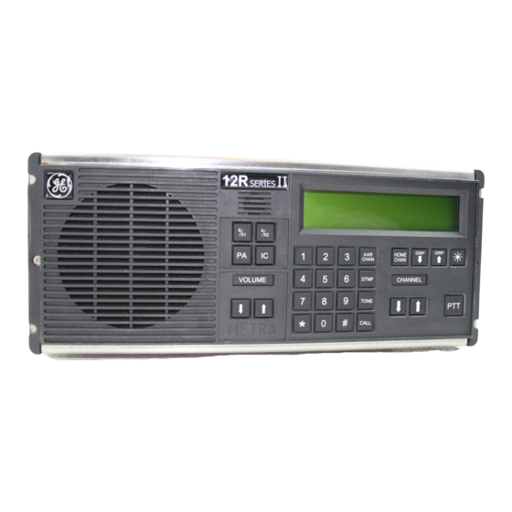
COE Communications Engineering Document Author: Rev: Keith Gilbertson TRANSPORTATION SYSTEMS Date: 3/08/02 Title: GLOBAL SIGNALING DIVISION 12RII FCC TECHNICAL MANUAL FRONT PANEL SERIES AAR ch. 30 BNSF DISP. GRP TUNE DTMF HOME TONE CHANNEL VOLUME ICOM SEND Standard 12RII Front Panel Controls Displays Channel &... -
Page 30: Block Diagram
COE Communications Engineering Document Author: Rev: Keith Gilbertson TRANSPORTATION SYSTEMS Date: 3/08/02 Title: GLOBAL SIGNALING DIVISION 12RII FCC TECHNICAL MANUAL Block Diagram RADIO PROCESSOR MODULE 4 x 8 KEYPAD ROW1 ROW1 ROW1 ROW1 J1-TO RADIO 24C64 COL1 COL2 EEPROM COL3 COL4 MIC-AUD COL5... -
Page 31: Front Panel Parts List
COE Communications Engineering Document Author: Rev: Keith Gilbertson TRANSPORTATION SYSTEMS Date: 3/08/02 Title: GLOBAL SIGNALING DIVISION 12RII FCC TECHNICAL MANUAL 12.1. Front Panel Parts List 227410-000 ASSY 12RII FRONT PANEL GSPN DESCRIPTION REF DES / DIN 227410-100 ASSY 12RII FRONT PANEL BOARD 202926-000 ASSY 12RII PROCESSOR MODULE 022207-100... -
Page 32: Front Panel Board Parts List
COE Communications Engineering Document Author: Rev: Keith Gilbertson TRANSPORTATION SYSTEMS Date: 3/08/02 Title: GLOBAL SIGNALING DIVISION 12RII FCC TECHNICAL MANUAL 12.2. Front Panel Board Parts List 227410-100 ASSY 12RII FRONT PANEL BOARD GSPN DESCRIPTION REF DES / DIN 001358-101 CAP CER CHIP 50V 100pF 0805 C17-18 C41 C44-45 001360-102 CAP CER CHIP 50V 1000pF 10% 0805... -
Page 33: Front Panel Schematic
COE Communications Engineering Document Author: Rev: Keith Gilbertson TRANSPORTATION SYSTEMS Date: 3/08/02 Title: GLOBAL SIGNALING DIVISION 12RII FCC TECHNICAL MANUAL 12.3. Front Panel Schematic See Attached drawing 135631-000...