Advertisement
Quick Links
RESIDUAL CURRENT MEASUREMENT DEVICE
RCM 202-AB
User manual
Art no.: 33.03.388
Doc. no.: 2.002.145.0.e
09/2020
Janitza electronics GmbH
Vor dem Polstück 6
35633 Lahnau, Germany
Janitza electronics GmbH
Vor dem Polstück 6
1
Information about using this user manual
35633 Lahnau, Germany
1.1
General information
This user manual is intended exclusively for use by trained specialized electrotech-
nical personnel.
This user manual is a part of the product and makes reference to other devices from
Janitza electronics GmbH. Only the names of the respective device series are spec-
ified, but not all the associated types. Read this user manual before using the device.
Observe all safety requirements and warning notices. Failure to observe the instruc-
tions can lead to personal injury and/or damage to the product.
Keep the user manual through the entire service life of the product so it is available
for all users.
For this quick start, please also note further documentation on our homepage, such
as
-
user manual and safety instructions
NOTE
Further information - e.g. the manual - can be found in the download area at
www.janitza.com.
2
Safety instructions
2.1
Symbols used
WARNING
These symbols and the word "warning" are used when there is possible
danger to life and limb.
Symbols are also used in these instructions that refer directly to the source
of danger.
ATTENTION
This symbol and the word "attention" are used when there is the possibility
of property damage.
Observe the user manual!
2
This symbol and "Observe the user manual!" are used when reference must
be made to the user manual or other documentation.
NOTE
This symbols and the word "Note" are used to make reference to additional
information necessary for device use.
2.2
General safety instructions
The following safety instructions must be observed for work on and with the RCM
202-AB. Specific safety instructions are also listed in the respective chapters.
WARNING
All work necessary for the connection, assembly, commissioning and oper-
ation of the device may only be performed by well trained and instructed
specialist personnel. The specialist personnel must observe and comply
with the relevant applicable standards and directives for work on electrical
systems (e.g. DIN EN 50110 and ff./ directives and regulations of profes-
sional associations in Germany).
ATTENTION
Use of the device requires sufficient knowledge of the product as well as
knowledge about the connected devices and systems. Changes to the pre-
set values and control commands influence the evaluation behavior of the
RCM 202-AB
residual current measurement device. Therefore changes to the commis-
sioning settings as well as the replacement of devices may only be carried
out upon agreement with Janitza electronics GmbH!
Changes carried out are to be documented in the system documentation!
Observe the user manual!
This user manual as well as the device-specific user manuals for connected
devices must be strictly observed.
NOTE
The RCM 202-AB is supplied as a component of a residual and operating
current monitoring system. Upon commissioning/delivery of a monitoring
system, all system-specific settings and control commands for the RCM
202-AB shall be parameterized and documented by Janitza electronics
GmbH.
3
Purpose - Intended use
The RCM 202-AB is a two-channel residual current measurement device for the
measurement and monitoring of main distribution boards up to a maximum residual
current of 20 A.
With connected current measurement transformers (also current sensors), the RCM
202-AB is used for the measurement and monitoring of residual currents in TN and
TT systems (grounded AC systems).
With additional devices of the RCM series, display devices or devices for data cou-
pling to third-party systems, it forms a complete residual and operating current moni-
toring system. This monitoring system increases system and operational safety.
Faults or an increase in residual currents (usually creeping) are detected early on, for
example, thus allowing preventative maintenance. The external signal current circuits
used in the monitoring system shall be secondary current circuits.
Any use of the RCM 202-AB that differs from the description in this manual is consid-
ered improper use and may affect the protection provided by the device.
4
4
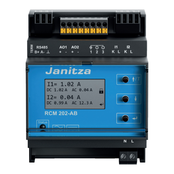
Overview of the RCM 202-AB
4.1
Device view
8
9
10
7
6
5
Fig. 1:
RCM 202-AB device view
1
Connection for 2 current measurement
transformers
2
Operating keys
3
Label with manufacturer, serial number
and item number
4
Supply voltage connection
5
Status LED
6
Display
4.2
Device dimensions
RCM 202-AB
Fig. 2:
Device dimensions in mm
5
Functions
5.1
Basic functionality
The main functions of the RCM 202-AB are:
Residual current measurement via a connected current measurement trans-
former (max. 2 current measurement transformers)
Transformer connection monitoring for wire breaks or short circuit per channel
Effective value measurement (true RMS)
Parallel measured value recording
Evaluation of fault currents (residual currents) type A and B according to IEC
62020
Detection of sinusoidal residual fault currents with frequencies up to 20 kHz
(type B+)
Measured value and extreme value storage with time stamp
Parameterizable alarm threshold for alarm message per channel
Parameterizable warning threshold (e.g. prewarning) for warning message per
channel
Parameterizable delay times:
Delay time for warning and alarm messages
Reset delay time for warning and alarm messages
Operating and error messages shown on the display
Communication via Modbus (RS485 interface/Modbus RTU)
Evaluation possibility with the help of the GridVis
6
play and evaluation device
5.1.1
Residual current monitoring principle
The fault currents (residual currents) flowing to ground or other paths are recorded
via the connected current measurement transformers.
RCM 202-AB
For example:
Outflow-related residual currents (consumers and systems)
Stray currents in TN-S systems (PEN and N conductors)
ATTENTION
Do not route the PE conductor through the current measurement trans-
former!
3
Fig. 3:
Simplified presentation of residual current measurement
5.1.2
Current measurement transformer monitoring
RCM 202-AB
The RCM 202-AB evaluates currents from up to two current measurement transform-
ers at the same time. For each active channel, the RCM 202-AB continuously checks
the connected transformer for short circuit or wire breaks. If a short circuit or wire
break occurs on the transformers, an error message is output on the display as well
as on the communication interfaces and the LED status flashes red.
5.2
RS485 interface (Modbus)
The RCM 202-AB has a Modbus interface (RS485) and works with the Modbus RTU
protocol as a slave. The device address 1 and the baud rate of 19200 baud are fac-
tory-set.
For more information, see the user manual at www.janitza.com
WARNING
The open ground connection of the RS485 interface may not be touched!
There is a risk of electric shock.
WARNING
The power supply connection and the transformer connections of the RCM
202-AB may be switched on only after connecting the ground terminal and
grounding the ground cable.
There is a risk of electric shock.
5.3
Digital outputs
ATTENTION
RCM 202-AB
1
2
3
4
7
Modbus termination switch
8
Modbus connection (RS485 interface)
9
Analog output connection (interface
4 ... 20 mA)
10 Digital output connection
5
®
monitoring system or a dis-
RCM 202-AB
7
5.3
Digital outputs
ATTENTION
External signal current circuits must be secondary current circuits if the
RCM 202-AB is integrated in a monitoring system.
The digital outputs are not short-circuit proof.
Cables that are longer than 30 m must be installed shielded.
The RCM 202-AB has two transistor switching outputs. These digital outputs are elec-
trically isolated from the evaluation electronics via optocouplers.
The digital outputs switch direct current or alternating current loads.
The digital outputs switch loads independently of the polarity of the supply volt-
age.
5.4
Analog outputs (interfaces 4 ... 20 mA)
8
The RCM 202-AB has two analogue outputs (interfaces 4 ... 20 mA). The analogue
outputs output the effective value of the measured total current. Both analogue out-
puts require a separate power supply (DC 12 ... 24 V).
Further information can be found in the user manual at www.janitza.de
6
Connection assignment
Fig. 4:
Circuit diagram of the RCM 202-AB
Modbus (RS485 interface)
RCM 202-AB
Pin
Desig-
Meaning
nation
1
B+
D
/non-inverted signal
+
2
A–
D
/inverted signal
–
3
Reference potential (GND)
Analog and digital output connection
1
AO1+
Analog output 1 (4 ... 20 mA sink +)
2
AO1–
Analog output 1 (4 ... 20 mA sink -)
3
AO2+
Analog output 2 (4 ... 20 mA sink +)
4
AO2–
Analog output 2 (4 ... 20 mA sink -)
5
-
-
6
1
Common connection for both digital outputs
7
2
Digital output 1
8
3
Digital output 2
Current measurement transformer connection
Current measurement transformer 1, contact k (wire color
1
I1 – K
2
I1 – L
Current measurement transformer 1, contact l (wire color
brown)
Current measurement transformer 2, contact k (wire color
3
I2 – K
Current measurement transformer 2, contact l (wire color
4
I2 – L
brown)
Power supply connection
1
N
Supply voltage AC 90 ... 230 V (N)
2
L
Supply voltage AC 90 ... 230 V (L)
Tab. 1:
Connection assignment RCM 202-AB
Bus termination
TERM switch
Switch position
On
RH
Resistance (120 Ω) switched on
(first and last bus
participant)
Off
Left
No resistance
Tab. 2:
Bus termination via the TERM switch
1)
for transformers with fixed connection cables without contacts k and l
7
Application example
10
7.1
Application example RCM 202-AB in stand-alone mode
Fig. 5:
Connection of two relays to the digital outputs
7.2
Application example analog outputs (interface 4 ... 20 mA)
Fig. 6:
Connection of a display device and a PLC to the analog outputs
(Power supply: Janitza power supply unit, art. no. 16.05.012)
RCM 202-AB
RCM 202-AB
9
1)
: white)
1)
:
: white)
1)
1)
:
Resistance
RCM 202-AB
11
Advertisement

Related Manuals for janitza RCM 202-AB


Summary of Contents for janitza RCM 202-AB
- Page 1 There is a risk of electric shock. Any use of the RCM 202-AB that differs from the description in this manual is consid- ered improper use and may affect the protection provided by the device.
- Page 2 Device safety The device address 1 and the baud rate of 19200 baud are factory-set. If the RCM 202-AB is the first or last device in the Modbus line, the termina- Safety regulations for electrical measurement, control, regulation and laboratory devices tion resistor must be set.