
Related Manuals for E-Mon Din-Mon D5


Summary of Contents for E-Mon Din-Mon D5
- Page 1 Din-Mon Smart Meter ™ Advanced kWh/Demand Meters with Communication INSTALLATION INSTRUCTIONS E-Mon 1985 Douglas Drive North Golden Valley, MN 55422 (800) 334-3666 www.emon.com info@emon.com 62-0442-05...
-
Page 2: Table Of Contents
Before installing your new E-Mon product, please read the information on the following pages carefully. We believe that you will find the E-Mon D-Mon meters easy to install and to use for monitoring and evaluating your electrical usage. - Page 3 DIN-MON™ SMART METER Section 4.5.3 Current Sensor Wiring............23 Section 4.5.4 Multiple-Load Monitoring ..........24 Section 4.6 Main Power and Current Sensor Wiring Diagram....25 Section 4.6.1 4-Wire Wye, 3-Element Connection Diagram....25 Section 4.6.2 3-Wire Delta, 3-Element Connection Diagram ....25 Section 4.6.3 3-Wire, 2-Element Connection Diagram......
-
Page 4: Safety Label Definitions And Information
DIN-MON™ SMART METER Section 7.2.6 Setting Communication Protocol ........44 Section 7.2.7 Setting Communication Baud Rate ........45 Section 7.2.8 Setting Phase Loss or VAR-Hour Pulse ......45 Section 7.2.9 Setting CT Selection............46 Section 7.2.10 Setting Access Protection ..........46 Section 7.2.11 Changing Password............ -
Page 5: Precautionary And Safety Information
DIN-MON™ SMART METER FCC NOTICE This equipment has been tested and found to comply with the limits for a Class B digital device, pursuant to part 15 of the FCC Rules. These limits are designed to provide reasonable protection against harmful interference in a residential installation. This equipment generates, uses and can radiate radio frequency energy and, if not installed there is no guarantee that interference will not occur in a particular installation. -
Page 6: Introduction
Meter (top angle view with covers). Installation must only be performed by qualified personnel and in accordance with these instructions and all applicable local and national electrical codes. E-Mon and its representatives assume no responsibility for damages or injury resulting from the improper installation of this meter. - Page 7 DIN-MON™ SMART METER Fig. 3. Model D2 Meter (top view with cover removed). Verify the input voltage rating, amperage, sensor type and configuration on the meter name plate (located on the left side of the meter) to ensure that it is suitable for the intended electrical service.
- Page 8 NOTE: If any trouble arises during installation or functional verification opera- tions, do not immediately remove the unit. Before removing the unit, contact E-Mon’s technical support department at (800) 334-3666. E- Mon’s technical department will assist you in detailed troubleshooting of the Din-Mon™...
-
Page 9: Meter Technical Specifications
DIN-MON™ SMART METER 2.0 METER TECHNICAL SPECIFICATIONS 2.1 Ordering Information Example KIT3 E-D5-480100-S03SPL3-V3KIT3 Brand E=E-Mon D-Mon Class D2 = Din-Mon™ kWh Meter D5 = Din-Mon™ Advanced kWh Meter Voltage (Input) 120=120V (L-N) 208=120/208V, 127/220V (L-L) 480=277/480V (L-L) 600=347/600V (L-N) 400=220/380V, 230/400V, or 240/415V (L-N) -
Page 10: Technical Specifications
DIN-MON™ SMART METER 2.2 Technical Specifications Input Voltage 2-wire single phase, 3-wire single phase, 3-wire (Delta), Configuration or 4-wire (WYE) Mains Voltage Input Up To 600 VAC RMS Available Meter Input Power 6 VA Maximum Current Sensor Up To 800 Amps RMS AC Rating Power Factor 0.5 Leading Or Lagging... - Page 11 DIN-MON™ SMART METER Battery Cell Description Non-rechargeable Cell Used For Memory Retention and Manufacturer Panasonic Manufacturer Part No CR2032 Working Voltage 3 VDC Current Capacity 225 mAHr Electrolyte Manganese Dioxide Lithium RS-485 Serial Cable UL-listed stranded conductors Communications 22-26 AWG, Belden 3106A (3- wire) Input / Output Voltage Grounded-isolated +/-5.4 VDC...
-
Page 12: Meter Overview
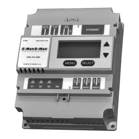
DIN-MON™ SMART METER 3.0 METER OVERVIEW The unit is comprised of 3 main components, the Main Power Connections, the Sensor Input Terminals and the Communication Ports and Terminals. COMMUNICATION PORTS AND TERMINALS MAIN POWER SENSOR INPUT INPUT TERMINALS TERMINALS M34553 Fig. -
Page 13: Communication Ports And Output Contact Terminals
DIN-MON™ SMART METER 3.2 Communication Ports and Output Contact Terminals The Communication Ports and Output Contact Terminals are located along the top edge of the meter. VAR-HOUR OPTIONAL OR PHASE LONWORKS RS-485 LOSS OUTPUT OR ETHERNET WATT-HOUR NETWORK TERMINALS RJ-45 PULSE OUTPUT INPUT BATTERY... -
Page 14: Terminal Covers
DIN-MON™ SMART METER LonWorks (optionally available on Din-Mon™ D5 meters) is a protocol used to communicate via TP/FT-10 (Twisted Pair / Free Topology) network. It allows the end user to read meter point data via SNVT’s (Standard Network Variable Types). The Din-Mon™... -
Page 15: Meter Installation
Installation must only be performed by qualified personnel and in accordance with these instructions and all applicable local and national electrical codes. E-Mon and its representatives assume no responsibility for damages or injury resulting from the improper installation of this meter. -
Page 16: Din-Rail Mounting
DIN-MON™ SMART METER 4.3 DIN-Rail Mounting The meter mounts on the DIN Rail using the flex connects at bottom of the enclosure. To install the meter on the DIN perform the following steps: 1. Holding the meter with its top tilted in towards the DIN rail, hook the two top tabs on the back of the meter onto the top of the DIN rail. -
Page 17: Wiring The Voltage
DIN-MON™ SMART METER 4.4 Wiring the Voltage WARNING High voltages are present on voltage input connections screw terminals. Risk of serious injury and/or electrical shock exists. Prior to performing any wiring operations, review all contents of the user manual and de- energize the MAINS power switch. - Page 18 DIN-MON™ SMART METER c. The terminal cover has breakable teeth to let the wires feed through, break the teeth as needed. Replace the terminal cover and secure in place. d. Energize the AC main power input. The meter display will light up showing the startup screens, then scroll through the following screens.
-
Page 19: Phasing Of Line Voltage
DIN-MON™ SMART METER 4.4.1 Phasing of Line Voltage The 3-phase AC power input must be in proper phase sequence. If the sequence is incorrect or a phase is missing, there will be a message on the meter’s display: “PH Seq Err” or “PH Loss x” where ‘x’ is the missing phase. (Refer to the section on Line Voltage Diagnostics if this message is present.) When the line voltage is connected correctly , the error message will not be present. -
Page 20: Wiring Current Sensor Inputs
DIN-MON™ SMART METER 4.5 Wiring Current Sensor Inputs Once the AC voltages have been confirmed to be within acceptable limits, you are ready to install the current sensors. De-energize the meter for this procedure. In the lower right corner of the meter are the sensor connection terminals. Each sensor connects to two terminals, one labeled “WHT”... -
Page 21: Installing Split-Core Current Sensor Assembly
DIN-MON™ SMART METER 4.5.1 Installing Split-Core Current Sensor Assembly 1. Each phase being monitored will require one split-core current sensor assembly. Open the current sensor assembly by lifting the top off the sensor. SOURCE LOAD M35137 Fig. 14. Typical Split Core Current Sensor. 2. -
Page 22: Installing Solid-Core Current Sensor
DIN-MON™ SMART METER 4.5.2 Installing Solid-Core Current Sensor NOTE: Under no circumstances is this operation to take place without shutting off the power to the conductor(s) being monitored. LINE SOURCE LOAD Fig. 16. Typical Solid-Core Current Sensor. 1. With the power off, disconnect the conductor from its breaker or terminal. 2. -
Page 23: Current Sensor Wiring
DIN-MON™ SMART METER 4.5.3 Current Sensor Wiring Once the current sensors are installed onto their appropriate phase conductors, you can begin terminating the current sensors onto the meter. The current sensor wires can be extended up to 500 feet for remote monitoring applications. To extend the length of the wires, use #22 AWG twisted-pair wire with one white and one black wire. -
Page 24: Multiple-Load Monitoring
DIN-MON™ SMART METER 4.5.4 Multiple-Load Monitoring The Din-Mon™ kWh meter provides extreme flexibility by allowing additional sets of current sensors to be used in parallel so multiple load locations can be monitored by one meter. This feature allows totalized display readout from two or more load circuits. NOTE: Paralleling of current sensors applies only to those designed for 0.333V output (“V3”);... -
Page 25: Main Power And Current Sensor Wiring Diagram
DIN-MON™ SMART METER 4.6 Main Power & Current Sensor Wiring Diagram 4.6.1 4-Wire Wye, 3-Element Connection Diagram 1. Recommended fuses or circuit breaker per the national electrical code (meter load 6VA); refer to Technical Specification section. 2. Install current sensors according to instructions. SENSORS MAINS V3 VN... -
Page 26: 2-Wire, 1-Element Connection Diagram
DIN-MON™ SMART METER 4. Install jumper wire between “W” and “B” on Sensor 3 (ÆC). SENSORS MAINS V3 VN 1/2 A ØA ØB LOAD SOURCE ØC M35107 Fig. 21. 1-Phase, 3-Wire (120/240V, 120/208V, 277/480V) 4.6.4 2-Wire, 1-Element Connection Diagram 1. Recommended fuses or circuit breaker per the national electrical code (meter load 6VA). -
Page 27: Installation Diagnostics
DIN-MON™ SMART METER 4.7 Installation Diagnostics Following is a list of diagnostic messages that may appear on the meter display. DIAGNOSTIC MESSAGES SHOULD NOT BE ON CONTINUOUSLY WHEN THE METER IS INSTALLED PROPERLY AND IS IN WORKING ORDER. 4.7.1 Line Voltage Diagnostics The diagnostics program detects line voltage faults by displaying one of two messages: Error Messages:... - Page 28 DIN-MON™ SMART METER NOTE: If you have connected the current sensor to all terminals and the error message is still appearing, reverse the black and white wires and repeat the previous steps until the correct connection is found. If the CT Error message is eliminated, you have found the correct sensor connection;...
-
Page 29: Wiring The Communications
DIN-MON™ SMART METER 4.8 Wiring the Communications 4.8.1 RS-485 Network and Wiring RS-485 communication allows a computer, automation system, or modem to communicate with one or more Din-Mon™ meters. You can connect as many as 52 meters along a 4,000-foot RS-485 cable run BELDEN 3106A with Belden 3106A cable or equivalent. -
Page 30: Meter Rs-485 Wiring
4.8.3 USB Key Wiring The USB Key allows you to connect Din-Mon™ meters to a personal computer that has E-Mon Energy™ software installed. The USB key must be located within 15 feet of the host computer. UP TO 52 METERS ON RS-485 NETWORK... -
Page 31: Ethernet Wiring (Optional On D5 Models Only)
DIN-MON™ SMART METER 4.8.4 Ethernet Wiring (Optional on D5 Models Only) Ethernet/IP communication connections are provided through an RJ- ETHERNET JACK 45 connector on top of the meter. This port can be connected to a LAN for use as an Intranet or Internet connection; or can be connected directly to a network port of a PC using a Cat-5e crossover cable. -
Page 32: Lonworks Wiring (Optional On D5 Models Only)
DIN-MON™ SMART METER 4.8.5 LonWorks Wiring (Optional on D5 Models Only) LonWorks communication connections are provided through a 2-position screw terminal plug on top of the meter. This port can be connected to a LonWorks TP/FT-10 (Twisted Pair / Free Topology) network using 24 AWG twisted pair cable, TIA 568A Category 5 or equivalent. - Page 33 DIN-MON™ SMART METER LONWORKS SPECIFICATIONS 1. Supports up to 64 Devices / Nodes on a single network segment. 2. Supports 78 kbps bit rate. 3. TP/FT-10 accommodates Bus, Star, Loop, or combinations of topologies. 4. Bus Topology Specifications (Doubly Terminated): a.
-
Page 34: Communication Protocols
DIN-MON™ SMART METER 5.0 COMMUNICATION PROTOCOLS The Din-Mon™ meter supports multiple communication protocols. Refer to section 2.1 Ordering Information to check your meter model configuration to determine which protocol(s) it supports. • Refer to section “Wiring the Communications” for wiring details. •... -
Page 35: Modbus Tcp/Ip
All Din-Mon™ meters have EZ7 protocol on RS-485 and Ethernet built-in for communicating with E-Mon Energy software. EZ7 is an E-Mon proprietary protocol. The meter is shipped with a default EZ7 ID of 1A. The EZ7 ID range is 1A..1Z to 8A..8Z. -
Page 36: External Interface
DIN-MON™ SMART METER 6.0 EXTERNAL INTERFACE OUTPUT TERM The Din-Mon™ meter has 2 pairs of output terminals. 1. Watt-Hour pulse output. 2. VAR-Hour pulse or Phase Loss output. M35119 6.1 Pulse Output INTERNAL CIRCUIT The board contains two pulse outputs for use by Building Automation Systems, etc. -
Page 37: Pulse Type And Value
DIN-MON™ SMART METER 6.2 Pulse Type and Value The pulse outputs provided by the Din-Mon™ meter are VAR-Hour and Watt-Hour. The pulse value is dependent on the amperage size of the meter. See the chart below for the standard pulse values. Refer to section 10.2.6 Pulse Values for detailed instructions on changing settings. -
Page 38: Setting Up The Meter Using The Push Buttons
DIN-MON™ SMART METER 7.0 SETTING UP THE METER USING THE PUSH BUTTONS The meter has 4 push buttons (MENU, SELECT, UP, DOWN) located on the front of the meter. These buttons are used to program the following items: Item Function Description Date and Time Set month, day, year, and time... -
Page 39: Setup Menu Screens
DIN-MON™ SMART METER 7.1.1 Setup Menu Screens Item Program Main Menu Sub Menu Date and Time > DATE & TIME DATE 02-14-2013 DEVICE ID TIME 13:45-59 IP SETTINGS PULSE VALUE Device ID (Modbus DATE & TIME DEVICE ID > Firmware) DEVICE ID IP SETTINGS MODBUS... - Page 40 DIN-MON™ SMART METER Item Program Main Menu Sub Menu Phase Loss PROTOCOL PHASE LOSS BAUD RATE ENABLE > PHASE LOSS CT SELECTION CT Selection CT TYPE SPLIT PROTOCOL CT SIZE BAUD RATE PHASE LOSS > CT SELECTION Access Protect ACCESS PROTECT BAUD RATE REMOTE PHASE LOSS...
-
Page 41: Configurable Settings From The Display Menu
DIN-MON™ SMART METER 7.2 Configurable Settings from the Display Menu Item Main Menu Sub Menu Range Default Date &Time Date MM-DD-YYYY 00-00-0000 Time HH:MM:SS 00:00:00 Device ID EZ7 ID 1A..8Z Modbus ID 1..247 BACnet ID 0..1\4194303 IP Settings Enable DHCP? Y or N IP Address 255.255.255.255 192.168.0.1... -
Page 42: Setting Date And Time
DIN-MON™ SMART METER 7.2.1 Setting Date and Time To change the date and time, complete the following steps: DATE 02-14-2013 1. Press MENU button. TIME 13:45-59 2. Press SELECT button. The 2-digit month will be blinking. 3. Use UP or DOWN button to make changes. 4. -
Page 43: Setting Device Id (Bacnet)
DIN-MON™ SMART METER 7.2.3 Setting Device ID (BACnet) To change the Device ID, complete the following steps: DEVICE ID 1. Press MENU button. 2. Use UP or DOWN button until the arrow is on the BACNET DEVICE ID line. 3. Press SELECT button. 4. -
Page 44: Setting Pulse Value
DIN-MON™ SMART METER 7.2.5 Setting Pulse Value To change the Pulse Value, complete the following steps: OUT CHANNEL 1. Press MENU button. USE DEFAULT 2. Use UP or DOWN button until the arrow is on the WHr/P 1.95313 PULSE VALUE line. 3. -
Page 45: Setting Communication Baud Rate
DIN-MON™ SMART METER 7.2.7 Setting Communication Baud Rate To change the Communication Baud Rate, complete the following steps: BAUD RATE 9600 1. Press MENU button. 2. Use UP or DOWN button until the arrow is on the BAUD RATE line. 3. -
Page 46: Setting Ct Selection
DIN-MON™ SMART METER 7.2.9 Setting CT Selection To change the CT Selection, complete the following steps: CT TYPE SPLIT 1. Press MENU button. CT SIZE 2. Use UP or DOWN button until the arrow is on the CT SELECTION line. 3. -
Page 47: Changing Password
DIN-MON™ SMART METER 7.2.11 Changing Password To change the Password, complete the following steps: 0000 1. Press MENU button. 0000 2. Use UP or DOWN button until the arrow is on the CONFIRM PASSWORD line. 3. Press SELECT button. 4. Use UP or DOWN button to make changes. 5. -
Page 48: Resetting Meter Kwh/Kw
DIN-MON™ SMART METER 7.2.13 Resetting Meter kWh/kW To reset the meter kW and/or kWh readings, complete the RESET KW ONLY? following steps: RESET ALL? 1. Press MENU button. 2. Use UP or DOWN button until the arrow is on the RESET K/KWH READ line. -
Page 49: Normal Operating Modes
DIN-MON™ SMART METER 8.0 NORMAL OPERATING MODES The Din-Mon Meter is used to monitor electric power usage of individual loads after the utility meter and store kW and kVAR data for automatic meter reading. 8.1 Startup Screens When the meter starts up, the screen first displays the meter name and firmware image type. -
Page 50: Reading The Meter Display
DIN-MON™ SMART METER 8.2 Reading the Meter Display The Din-Mon meter features seven different screens showing monitoring data. Each screen is displayed for 5 second intervals, before scrolling onto the next screen. You can “lock” the scrolling display on any one of the seven screens. This will be explained in detail on following pages. -
Page 51: Display Hold Feature
DIN-MON™ SMART METER 8.3 Display Hold Feature You can hold the scrolling display so that it will stay locked on any one of the 7 screens. DISPLAY DOWN MENU SELECT M34559 Fig. 30. Display and Push Buttons. To Enter Hold Mode: 1. -
Page 52: Preventative/Scheduled Maintenance
DIN-MON™ SMART METER 9.0 PREVENTATIVE/SCHEDULED MAINTENANCE The unit is shipped in a calibrated and fully functional tested condition. Since the unit is factory-calibrated using proprietary firmware algorithms, no internal unit adjustments are necessary. This unit contains no internal adjustments, so no preventative or scheduled maintenance is required. -
Page 53: Lithium Battery Replacement
DIN-MON™ SMART METER 10.0 LITHIUM BATTERY REPLACEMENT The Din-Mon™ meter has a Lithium Battery Cell, which is used to retain the contents of the memory (SRAM) and the real-time clock (RTC) during power outages. The battery has a life expectancy of greater than 5 years. Nominal Working Voltage 3 Vdc Output Nominal Current Capacity... - Page 54 DIN-MON™ SMART METER WARNING eplace battery with Panasonic part number CR2032 only. Use of another battery may present a risk of explosion. See owner’s manual for safety instructions. Internal circuit card components are extremely sensitive to electrostatic discharge. Be careful not to touch internal circuitry prior to discharging any static buildup on your person.
-
Page 55: Frequently Asked Questions
DIN-MON™ SMART METER 11.0 FREQUENTLY ASKED QUESTIONS Q. When providing line voltage to the meter, can I tap off from the same breaker I am monitoring? A. Yes, the voltage can be pulled from the same breaker being monitored. Q. Can the meter’s line voltage wires be run in the same conduit as the sensor leads? A. - Page 56 Q. I’ve gone through the troubleshooting guides and I still can’t get my meter to work. What should I do? A. Before removing the unit, contact E-Mon’s technical services department at (800) 334-3666. E-Mon’s technical department will assist you in troubleshooting of the meter installation and assist you in getting the unit running.
-
Page 57: Meter Limited Warranty
DIN-MON™ SMART METER 12.0 METER LIMITED WARRANTY Subject to the exclusions listed below, E-Mon will either repair or replace (at its option) any product that it manufactures and which contains a defect in material or workmanship. The following exclusions apply: 1. -
Page 58: Appendix A Modbus Point Map
DIN-MON™ SMART METER APPENDIX A: MODBUS POINT MAP ADDRESS TYPE DESCRIPTION UNITS Integer Energy delivered Wh Pulse 40001 Energy received Wh Pulse Integer 40003 Integer Reactive energy delivered VARh Pulse 40005 Reactive energy received VARh Pulse Integer 40007 Energy delivered Float 41001 Energy received... - Page 59 DIN-MON™ SMART METER ADDRESS TYPE DESCRIPTION UNITS Voltage, line phase B to N Volts-N 41061 Float 41063 Float Voltage, line phase C to N Volts-N 41065 Float Voltage, line phase A to B Volts-L Voltage, line phase B to C Volts-L 41067 Float...
-
Page 60: Appendix Bbacnet Objects
DIN-MON™ SMART METER APPENDIX B: BACNET OBJECTS INSTANCE BACNET OBJECT DESCRIPTION UNITS PROPERTY Analog Input Energy delivered Present Value Analog Input Energy received Present Value Analog Input Reactive energy delivered kVARh Present Value Analog Input Reactive energy received kVARh Present Value Analog Input Real power Present Value Analog Input Reactive power... - Page 61 DIN-MON™ SMART METER INSTANCE BACNET OBJECT DESCRIPTION UNITS PROPERTY Analog Input Phase angle, phase B Degree Present Value Analog Input Phase angle, phase A Degree Present Value Analog Input Reserve A No units Present Value Analog Input Reserve B No units Present Value Analog Input Reserve C No units Present Value INSTANCE...
- Page 62 DIN-MON™ SMART METER PIC S TATEMENT BACNET PROTOCOL IMPLEMENTATION CONFORMANCE STATEMENT Vendor Name: E-Mon Vendor ID: Product Name: Din-Mon™ Meter Product Model Numbers: D2 Smart Meter, D5 Advanced Smart Meter Product Description Kilo-watt hour meter BACnet Standardized Device Profile (Annex L):...
-
Page 63: Appendix C Lonworks Protocol Data Points
DIN-MON™ SMART METER APPENDIX C: LONWORKS PROTOCOL DATA POINTS NETWORK VAR BLK VAR SNVT DESCRIPTION UNITS SNVT_count_32 Energy delivered pulse Wh Pulse nvoWh_DelPulse SNVT_count_32 Energy received pulse Wh Pulse nvoWh_RecPulse SNVT_count_32 Reactive energy VARh nvoVARh_RecPulse delivered SNVT_count_32 Reactive energy received VARh nvoVARh_DelPulse SNVT_count_inc_f Energy delivered... - Page 64 DIN-MON™ SMART METER NETWORK VAR BLK VAR SNVT DESCRIPTION UNITS nvoVolt_LL_PhA_B SNVT_volt_f Voltage line-line phase A- Volts-L nvoVolt_LL_PhB_C SNVT_volt_f Voltage line-line phase B- Volts-L nvoVolt_LL_PhC_A SNVT_volt_f Voltage line-line phase C- Volts-L nvoPhase_AngleA SNVT_count_inc_f Phase angle, phase A Degree nvoPhase_AngleB SNVT_count_inc_f Phase angle, phase B Degree nvoPhase_AngleC SNVT_count_inc_f Phase angle, phase A...
- Page 65 DIN-MON™ SMART METER NOTE DESCRIPTION To clear kWh and kVARh, set nviResetUsageCh to 1. To clear nvoExt_Input_1, set nviResetUsageCh to 2. To clear nvoExt_Input_2, set nviResetUsageCh to 3. To clear nvoPeak_Dem, set nviResetUsageCh to 4. To set the real time clock, set nviRTC_DateTime to the desired date and time. nvoIntervalData will display the number of pulses for the selected interval period and channel.
- Page 66 DIN-MON™ SMART METER CONFIG. PROPERTY BLK VAR DESCRIPTION UNITS UCPTMinSndTWh_DelPulse Min. time to propagate NV Seventeenth UCPTMaxSndTWh_DelPulse Max. time to propagate N SNVT_count UCPTMinSndTWh_RecPulse Min. change in value to propagate Unsigned quad UCPTMaxSndTWh_RecPulse Min. time to propagate NV SNVT_count UCPTSendDeltaWh_RecPulse Max.
- Page 67 DIN-MON™ SMART METER CONFIG. PROPERTY BLK VAR DESCRIPTION UNITS UCPTSendDeltaCurrent_Avg Max. time to propagate NV SNVT_count_f UCPTMinSndTVolt_LN Min. time to propagate NV SNVT_count UCPTMaxSndTVolt_LN Max. time to propagate NV SNVT_count UCPTSendDeltaVolt_LN Min. change in value to propagate SNVT_count_f UCPTMinSndTVolt_LL Min. time to propagate NV SNVT_count UCPTMaxSndTVolt_LL Max.
- Page 68 DIN-MON™ SMART METER CONFIG. PROPERTY BLK VAR DESCRIPTION UNITS UCPTSendDeltaPwr_Fact_Ph Min. time to propagate NV SNVT_count UCPTMinSndTPwr_Fact_PhB Min. time to propagate NV SNVT_count UCPTMaxSndTPwr_Fact_PhB Max. time to propagate NV SNVT_count UCPTSendDeltaPwr_Fact_Ph Min. change in value to propagate SNVT_count_f UCPTMinSndTPwr_Fact_PhC Min. time to propagate NV SNVT_count UCPTMaxSndTPwr_Fact_PhC Max.
- Page 69 DIN-MON™ SMART METER CONFIG. PROPERTY BLK VAR DESCRIPTION UNITS UCPTSendDeltaPhase_Angle Min. time to propagate NV SNVT_count UCPTMinSndTReserve_A Min. time to propagate NV SNVT_count UCPTMaxSndTReserve_A Max. time to propagate NV SNVT_count UCPTSendDeltaReserve_A Min. change in value to propagate SNVT_count_f UCPTMinSndTReserve_B Min. time to propagate NV SNVT_count UCPTMaxSndTReserve_B Max.
-
Page 70: Appendix D Troubleshooting
DIN-MON™ SMART METER APPENDIX D: TROUBLESHOOTING ITEM MESSAGES DESCRIPTION NOTE PH Seq Err Pase rotation is incorrect - See Section 4.7.1 Line Voltage Diagnostics on page 27 PH Loss X At least one phase is missing, where X is the missing phase CT Err A Current sensor is installed incorrectly - see... - Page 71 DIN-MON™ SMART METER 62-0442—05...
- Page 72 DIN-MON™ SMART METER By using this E-Mon literature, you agree that E-Mon will have no liability for any damages arising out of your use or modification to, the literature. You will defend and indemnify E-Mon, its affiliates and subsidiaries, from and against any liability, cost, or damages, including attorneys’...