Advertisement
INSTALLATION & OPERATION MANUAL
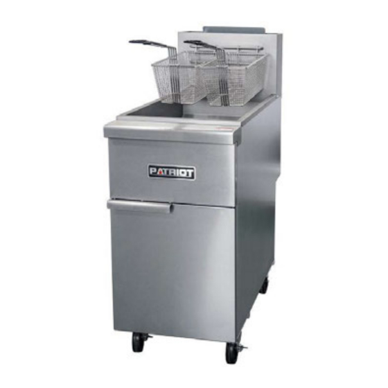
Gas Floor Model Fryers
Model PT-F3-NG
Model PT-F4-NG
Model PT-F5-NG
PT-F3-LP
PT-F4-LP
PT-F5-LP
(3 Burners Fryer)
(4 Burners Fryer)
( 5 Burners Fryer)
WARNING: IMPROPER INSTALLATION, ADJUSTMENT, ALTERATION, SERVICE OR MAINTENANCE
CAN CAUSE PROPERTY DAMAGE, INJURY OR DEATH. READ THE INSTALLATION, OPERATING AND
MAINTENANCE INSTRUCTIONS THOROUGHLY BEFORE INSTALLING OR SERVICING THIS EQUIPMENT.
Please call the Service Department and ask for contact information for your local service company.
1
Advertisement

Related Manuals for Patriot PT-F3-NG

Summary of Contents for Patriot PT-F3-NG
- Page 1 INSTALLATION & OPERATION MANUAL Gas Floor Model Fryers Model PT-F3-NG Model PT-F4-NG Model PT-F5-NG PT-F3-LP PT-F4-LP PT-F5-LP (3 Burners Fryer) (4 Burners Fryer) ( 5 Burners Fryer) WARNING: IMPROPER INSTALLATION, ADJUSTMENT, ALTERATION, SERVICE OR MAINTENANCE CAN CAUSE PROPERTY DAMAGE, INJURY OR DEATH. READ THE INSTALLATION, OPERATING AND MAINTENANCE INSTRUCTIONS THOROUGHLY BEFORE INSTALLING OR SERVICING THIS EQUIPMENT.
- Page 2 SAFETY PRECAUTIONS Before installing and operating this equipment, be sure everyone involved in its operation is fully trained and aware of precautions. Accidents and problems can be caused by failure to follow fundamental rules and precautions. The following symbols, found throughout this manual, alert you to potentially dangerous conditions to the operator, service personnel, or to the equipment.
-
Page 3: Table Of Contents
NOTICE Gas floor model fryers are intended for commercial use only. Not for household use. Warranty will be void if service work is performed by other than a qualified technician, or if other than genuine replacement parts are installed. Be sure this Operator’s Manual and important papers are given to the proper authority to retain for future reference. -
Page 4: Specifications
PECIFICATIONS DIMENSIONS Note: for mm, multiply inches by 25.4 Width (in) Depth (in) Height (in) Gas Connection Total Crated Model (in) BTU/hr Weight (lbs) 3 burner 15.5 14.0 30.3 14.0 47.2 34.7 90,000 fryer 4 burner 15.5 14.0 30.3 14.0 47.2 34.7 120,000... -
Page 5: Installation
Gas Supply and Burner Information Supply pressure should be minimum of 4" W.C. for natural gas or 10" W.C. for propane. The fryer comes with ¾” NPT male connector on a ½” pipe, allowing you to connect with either ¾” or ½” NPT female connector. - Page 6 Step 1: Unpack IMMEDIATELY INSPECT FOR SHIPPING DAMAGE All containers should be examined for damage before and during unloading. The freight carrier has assumed responsibility for safe transit and delivery. If damaged equipment is received, either apparent or concealed, a claim must be made with the delivering carrier. Apparent damage or loss must be noted on the freight bill at the time of delivery.
- Page 7 NOTICE Unit must be level to assure maximum performance. Improper leveling may void warranty. NOTICE When this appliance is installed with casters, it must be installed with the casters supplied, a connector complying with either ANSI Z21.69 CSA 6.16 and a quick-disconnect device complying with ANSI Z21.41 CSA 6.9.
- Page 8 Step 3: Flue Installation 1. Unpack the flue box and flue wrap 2. Slide the flue box over the flue and secure it with the two self-tapping screws using a 5/16” socket 3. Slide the flue wrap over the flue...
- Page 9 4. Secure it with four self-tapping screws two on the back and one on each side using a 5/16” socket Step 4: Check Clearances and Ventilation Select a firm, level location for your fryer. Leave clearance, whenever possible, so that access from the rear is possible to permit cleaning.
- Page 10 Due to the variety of problems that can be caused by outside weather conditions, venting by canopies or wall fans is preferred over any type of direct venting. It is recommended that a canopy extend 6" past the appliance and the bottom edge be located 6'6" from the floor. Filters should be installed at an angle of 45° or more from the horizontal.
- Page 11 CAUTION ALL PIPE JOINTS AND CONNECTIONS MUST BE TESTED THOROUGHLY FOR GAS LEAKS. USE ONLY SOAPY WATER FOR TESTING ON ALL GASES. NEVER USE AN OPEN FLAME TO CHECK FOR GAS LEAKS. ALL CONNECTIONS MUST BE CHECKED FOR LEAKS AFTER THE UNIT HAS BEEN PUT INTO OPERATION.
-
Page 12: Operation
PHOTO 1 PERATION LIGHTING CAUTION IF YOU SMELL GAS DURING THE LIGHTING PROCEDURE, IMMEDIATELY SHUT OFF THE GAS SUPPLY UNTIL THE LEAK HAS BEEN CORRECTED. Open the burner compartment door and do the following: 1. Turn thermostat to “OFF” 2. Press down the knob of the combination gas valve, turn it counterclockwise to the “PILOT” position (shown), and continue to press the knob down. - Page 13 FILLING THE FRYPOT 1. Close drain valve completely before filling the frypot. 2. When the fryer is new, fill the frypot with water and clean thoroughly (see “Weekly Cleaning” on page 15) in order to remove protective coatings and any foreign matter. 3.
-
Page 14: Cooking Hints
HIGH LIMIT CONTROL Gas floor model fryers are equipped with a secondary heat control that prevents the oil temperature from rising above 450F. (Because of the accuracy tolerance of the sensor, the oil temperature may reach as high as 475F.) In the event the fryer shuts down due to this condition, the oil must be cooled to below 400F before the pilot burner can be re-ignited. - Page 15 4. Wipe off the basket support frame and the inside of the frypot with a clean cloth. CAUTION SOME AREAS OF THE FRYPOT MAY BE HOT! 5. Close drain valve and strain the oil back into the frypot through several thicknesses of cheesecloth, or filter it back using a filter machine.
-
Page 16: Service (For Authorized Service Technician Only)
cleanser. Heat tint action may be lessened by not applying or by reducing, heat to equipment during slack periods. ERVICE F OR AU T H OR I Z E D S E R V I C E T E C H N I C I AN O N LY NOTICE Warranty will be void and the manufacturer is relieved of all liability if: (A) Service work is performed by other than a qualified technician (see page 30 for detail) - Page 17 CHECKING AND ADJUSTING PRESSURE REGULATOR The combination gas valve (includes pressure regulator) is factory set at 4" W.C. for natural gas and 10" W.C. for propane gas. To check the manifold pressure, do the following: 1. Turn thermostat “OFF” and combination gas valve knob to the “PILOT” setting. 2.
- Page 18 CHECKING AND ADJUSTING AUTO SAFETY PILOT The pilot flame should surround the thermopile for 1/2". It must be large and sharp enough to cause the thermopile to glow a dull red, or sufficient to hold the safety valve open. 1. Remove pilot adjustment cap 2.
- Page 19 Wiring Diagram...
-
Page 20: Parts
ARTS NOTICE INSTALLATION OF OTHER THAN GENUINE PARTS WILL VOID THE WARRANTY ON THIS EQUIPMENT. The serial plate is located inside the front door on the left side. Replacement parts may be ordered either through a Authorized Parts Distributor or a Authorized Service Agency. - Page 21 Gas Parts for Fryer (3 tube shown) Part Number Description PT-400045 Knob, thermostat PT-400044 Thermostat Fryer, regulating 200-400 PT-400042 Combination Valve (Nat)_Invensys PT-400146 Combination valve (LP)_Invensys PT-400242 Combination Valve (Nat)_Honeywell PT-400246 Combination valve (LP)_Honeywell PT-400070 Tubing, ¼” fryer pilot PT-300031 Burner, Fryer PT-400043 Safety thermopile 18”...
- Page 22 Tank Parts (3 tube shown) Part Number Description PT-400037 Screen, crumb, 3 and 4 tube fryer PT-400058 Screen, crumb, 5 tube fryer PT-400036 Valve, Ball PT-C200016 Tank, 3 tube fryer (excluding flue) PT-C200017 Tank, 4 tube fryer (excluding flue) PT-C400056 Tank, 5 tube fryer (excluding flue) PT-400071 Drain, extension...
- Page 23 PATRIOT FRYER A product with the Patriot name incorporates the best in durability and low maintenance. We all recognize, however, that replacement parts and occasional professional service may be necessary to extend the useful life of this unit. When service is needed, contact an Authorized Service Agency, or your dealer.
- Page 24 Patriot warrants its equipment against defects in materials and workmanship, subject to the following conditions: Patriot gas equipment is warranted for one (1) years, effective from the date of purchase by the original owner. A copy of the original receipt or other proof of purchase is required to obtain warranty coverage. This warranty applies to the original owner only, and is not assignable.