
Related Manuals for Casio CTK-810


Summary of Contents for Casio CTK-810
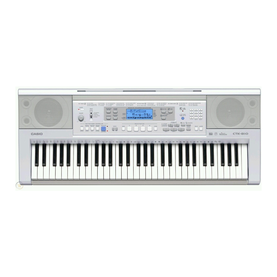
- Page 1 (without price) CTK-810 APR. 2007 CTK-810 ELECTRONIC KEYBOARD INDEX Ver.1 : May. 2005...
-
Page 2: Table Of Contents
CONTENTS Specifications ---------------------------------------------------------------------------------------------- 1 Block Diagram --------------------------------------------------------------------------------------------- 2 Circuit Description --------------------------------------------------------------------------------------- 3 Printed Circuit Boards ---------------------------------------------------------------------------------- 5 Disassembly ------------------------------------------------------------------------------------------------ 7 Diagnostic Program ------------------------------------------------------------------------------------ 12 Exploded View ------------------------------------------------------------------------------------------- 14 Parts List--------------------------------------------------------------------------------------------------- 15 Schematic Diagrams ----------------------------------------------------------------------------------- 18... -
Page 3: Specifications
Tempo : Variable (226 steps, = 30 to 255) Chords : 3 fingering methods (CASIO CHORD, FINGERED, FULL RANGE CHORD) Rhythm Controller : S TA RT / S TO P, I N T RO, N O R M A L / N O R M A L F I L L - I N ,... -
Page 4: Block Diagram
BLOCK DIAGRAM SUB PCB (M708-PSA1) Buttons D302 (9V) Button Controller LCD Controller IC402 IC401 uPD65881GK-1019E7A ST7066U-OA Power Supply Circuit SPEAKERS Q303 ~ Q305, D308 PWSW TXDO DB4 ~ DB7 RXDI Power Amplifier IC301 (9V) (5.3V) (5.3V) LA4635A-E Main Volume CONSOLE PCB Filter (M708-CNA2) IC302... -
Page 5: Circuit Description
CIRCUIT DESCRIPTION KEY MATRIX Note: Each key has two contacts, the first conatct 1 and second contact 2. First contact Second contact NOMENCLATURE OF KEYS F#3 G#3 A#3 F#4 G#4 A#4 C#5 D#5 F#5 G#5 A#5 C#4 D#4 C2 D2 G2 A2 C3 D3 G3 A3... - Page 6 METRONOME LAYER SCORING TRUCK 2 REGISTRATION Ð LEFT/ SWI1 STEP 1 SPEAK SPLIT TONE TRUCK 1 SWI2 RHYTHM FULL PIANO SONG CASIO SWI3 NORMAL FINGARD RANGE SETTING BANK CHORD CHORD TRANSEPOSE/ REVERB/ ONE TOUCH SWI4 RECORDER FUNCTION CHORUS PRESET VARIATION/...
-
Page 7: Printed Circuit Boards
PRINTED CIRCUIT BOARDS Main PCB M708-MDA1 Top View Bottom View Console PCB M708-CNA1 – 5 –... - Page 8 Sub PCB M708-PSA1 Keyboard PCB M708-KYA1 Keyboard PCB M708-KYA1 – 6 –...
-
Page 9: Disassembly
DISASSEMBLY 1. Remove the battery cover and then battery. 2. Remove 15 screws and then upper case. 3. Remove two lead wires by soldering. 4. Remove two connectors by soldering. 5. Make the keyboard unit and the main unit apart. Lead wires ■... - Page 10 ■ To remove the main PCB (M708-MDA1). 6. Remove three screws on the PCB (M708-MDA1). ■ Precaution while assembling the main Connector 1. 7. Remove two connectors by soldering. Number of pins on the PCB and pins on the 8. Remove the PCB (M708-MDA1). cable are different.
- Page 11 15. Remove 37 screws and then the PCB (M708-CNA1). Caution while assembling: 6 screws fixating the LCD unit must be screwed on in a designated order. When assembling, be sure to tighten the screws in the order from 1 - 6 shown in the photo. Failing to do so may cause display malfunctions.
- Page 12 ■ To remove the key PCBs (M709-KYA1, KYA2) 18. Remove 21 screws and then the white keys. 19. Remove the black keys. – 10 –...
- Page 13 20. Remove the rubber keys. Caution while assembling: There are two types of rubber keys and they are different in length. The longest rubber key ( ) must be installed at the right end. How to install the rubber keys. 21.
-
Page 14: Diagnostic Program
DIAGNOSTIC PROGRAM ■ ■ ■ ■ ■ Initial Setting 1. Connect the AC adaptor. 2. Connect a Sustain pedal. NOTE: If there is no Sustain pedal, Sustain pedal check can be skipped. 3. Connect to a PC through USB. (A USB driver must be installed on the PC.) 4. - Page 15 Message on LCD 4. ROM check 1 Press “2” button. 5. Version check 1 Press “3” button. 2 Press “3” button. 3 Press “3” button. 6. RAM check 1 Press “+” button. 7. Sound check 1 Press the “7” button. * When standing in the center, the tester hears the maximum test sound fromthe left speaker.
-
Page 16: Exploded View
EXPLODED VIEW – 14 –... -
Page 17: Parts List
PARTS LIST CTK-810 Notes: This parts list does not include the cosmetic parts, which parts are marked with item No. "R-X" in the exploded view. Contact our spare parts department if you need these parts for refurbish. 1. Prices and specifications are subject to change without prior notice. - Page 18 1 CTK-810_DI 2 CTK-810_EU 3 CTK-810_UK 4 CTK-810_US Parts Q'TY Price Item Parts Name Specification Remarks Code Main PCB 10271791 PCB ASSY/MAIN TK-RJM507852*001 10269340 IC XC6403FY51PR 10269339 IC XC6216B332PR IC13 10123002 IC TC74VHC174FT(EL) 10197555 IC TC7SZ14FU(TE85L.F) 10197809 IC TC7WH123FU(TE12L.F IC10 10261872 LSI CY62126EV30LL45ZST IC12...
- Page 19 1 CTK-810_DI 2 CTK-810_EU 3 CTK-810_UK 4 CTK-810_US Parts Q'TY Price Item Parts Name Specification R Remarks Code Keyboard Unit 10269451 RUBBER/CONTACT/CB RJM507656-001V01 10270393 RUBBER/CONTACT/CS RJM507657-001V01 10249864 WHITE KEY/CB TK-RJM507243*001 10249865 WHITE KEY/CS TK-RJM507244*001 10274032 BLACK KEY/10P RJM506595-001V02 10247548 BLACK KEY5P RJM506595-002V01 Case Unit 10269447 REFRECTOR...
-
Page 20: Schematic Diagrams
SCHEMATIC DIAGRAMS Main PCB M708-MDA1 – 18 –... - Page 21 Sub PCB M708-PSA1 – 19 –...
- Page 22 Console PCBs M708-CNA1, CNA2 – 20 –...
- Page 23 Keyboard PCBs M708-KYA1, KYA2 – 21 –...
- Page 24 CASIO COMPUTER CO.,LTD. Overseas Service Division 6-2, Hon-machi 1-Chome Shibuya-ku, Tokyo 151-8543, Japan...