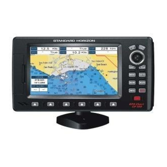
Standard Horizon CP180 Owner's Manual
Hide thumbs
Also See for CP180:
- Owner's manual (138 pages) ,
- Dimensions (1 page) ,
- Installation and operation manual (45 pages)
Table of Contents
Advertisement
Quick Links
Advertisement
Table of Contents

Related Manuals for Standard Horizon CP180


Summary of Contents for Standard Horizon CP180
- Page 2 Color GPS Chart Plotters CP180/CP180i CP300/CP300i Owner's Manual...
- Page 3 Consult an authorized STANDARD HORIZON dealer or other qualified service technician if the problem cannot be corrected. Operation is subject to the following...
- Page 4 · The GPS Chart Plotter contains dangerous high-voltage circuits which only experien- ced technicians can handle. · STANDARD HORIZON will not be liable for errors contained herein, or for incidental or consequential damages in connection with the performance or use of this material.
-
Page 5: Table Of Contents
2. GETTING STARTED ......................13 MOUNTING THE GPS CHART PLOTTER ............13 BRACKET MOUNTING ..................13 FLUSH MOUNTING ....................14 MOUNTING THE CP180 OR THE CP300 EXTERNAL GPS ANTENNA ..... 15 2.3.0 Flush mounting the antenna ..............16 CONNECTIONS ..................... 17 2.4.0... - Page 6 4. FIND SERVICES ....................... 41 USING FIND SERVICES & MORE FUNCTIONS ..........41 4.0.0 Port Services ....................41 4.0.1 Port ......................42 4.0.2 Tide Stations ....................42 4.0.3 Wrecks ....................... 43 4.0.4 Obstructions ....................44 4.0.5 Lakes Information ..................45 Quick Info On Lakes ..................
- Page 7 12. PAGES ..........................79 12.0 CHART PAGE ......................80 CP300/CP300i 12.0.0 Focus Soft Key on Dual Chart page ......81 CP180/CP180i 12.0.1 Change Focus on Dual Chart page ......81 12.0.2 Single Chart page ..................82 12.0.3 Window Selections ..................82 12.0.4 Customizing the Data Windows ..............
- Page 8 18.0.1 DIM Menu ....................113 18.0.2 Cartridges ....................114 18.0.3 Serial Ports ....................114 19. SPECIFICATIONS ......................115 19.0 CP180/CP180i SPECIFICATIONS ............... 115 19.1 CP300/CP300i SPECIFICATIONS ............... 116 19.2 OPTIONAL WAAS GPS RECEIVER SPECIFICATIONS ........117 20. APPENDIX: TERMS ....................... 118 ANALYTICAL INDEX ......................
-
Page 9: Introduction
1. INTRODUCTION Congratulations on your purchase of the STANDARD HORIZON GPS Chart Plotter. Whether this is your first STANDARD HORIZON product or not, we are committed to ensuring your enjoyment and satisfaction with this unit. Our Technical support personnel stand behind every product we sell. Post-Sales Support can be obtained from your dealer or distributor. -
Page 10: Packing List
Position Request calls · 3 year limited warranty, lifetime flat rate NOTE The screen imagines on this manual refer to the CP180/CP180i GPS Chart Plotters unless specified. PACKING LIST When the package containing the Navigation device is first opened, please check for the following contents. -
Page 11: Optional Accessories
MDS-10-5 4kW 48 Mile 5FT Open Array NOTE For UK customers: Please contact the STANDARD HORIZON Authorized dealer, STANDARD HORIZON product technical support or SI-TEX directly for additional information. For European customers: Please contact your local dealer for information. Page 12... -
Page 12: Getting Started
MOUNTING THE GPS CHART PLOTTER The CP180 and CP300 are available in either internal or external GPS antenna variants. The GPS Chart Plotters are designed for bracket or flush mounting and are supplied with both bracket and flush mounting kits. -
Page 13: Flush Mounting
After the location is found, attach the mounting base to the area using the supplied hardware. Figure 2.1 - Example of Bracket installation (CP180 on the left side and CP300 on the right side) FLUSH MOUNTING The CP180/CP180i and CP300/CP300i are supplied with a flush mounting template for the cutout hole and screw holes required to install the GPS Chart Plotter. -
Page 14: Mounting The Cp180 Or The Cp300 External Gps Antenna
MOUNTING THE CP180 OR THE CP300 EXTERNAL GPS ANTENNA The CP180 and CP300 are supplied with an external WAAS GPS antenna with 15 meter of routing cable. This antenna is designed to be mounted on a base, installed on an extension or even flush mounted. -
Page 15: Flush Mounting The Antenna
3FT of a Radar or other transmitting antennas. Ensure there are no major obstructions or fixtures in the immediate proximity to the antenna. The antenna relies on direct “line of sight” satellite reception. If you are unsure of the chosen location, temporarily mount the antenna in the desired location to verify correct operation. -
Page 16: Connections
NMEA to other devices (Autopilot, Radar…) you can parallel wires from the yellow, brown or white wires to other devices. NOTE* RS232 not opto-isolated electrical interface 2.4.0 CP180/CP180i Connection Table 12VDC Power cable Pin Wire Color Description Connection Example Additional Comments... -
Page 17: Cp300/Cp300I Connection Table
NOTE** AUTOPILOT CONNECTION Care must be taken when connecting the GPS Chart Plotter to an Autopilot. Normally Port3 (Yellow wire) will be used to connect to an Autopilot Input, however older Autopilots may not be able to read the sentences due to the talker ID that is being used (II Integrated Instrument). If the Autopilot connections are made to Port3 (Yellow wire) and the Autopilot is not reading the sentences, change the connections to Port1 (Brown wire) and change the sentences to APA, APB, BOD, GGA, GLL, RMC and XTE. -
Page 18: Cp180/Cp180I Connections
+ 9 / 12 VDC Connect to Video Cameras Power Input Video Signal + Connect to Video Signal + (NTSC/PAL) of DVD/VCR/Video Cameras 2.4.2 CP180/CP180i Connections 2.4.2.0 DC Power Connection 2.4.2.1 Connection of the FF525, AIS Receiver, VHF and Autopilot SMART GPS Antenna... -
Page 19: Cp300/Cp300I Connections
Input and Output wires are shown in gray and not used. 2.4.2.2 AIS Setup The CP180 or CP180i has to be set up to be able to receive NMEA information from the AIS Receiver. The GPS Chart Plotter reads the AIS NMEA message VMD, type 1, 2, 3 and 5 for AIS Class A and type 18, 19, 24 for AIS Class B. - Page 20 2.4.3.1 Connection a Video Camera, FF525, AIS Receiver, VHF and Autopilot NOTE Port2 Input and Output is used by the optional FF525. In the diagram above you will notice Port2 Input and Output wires are shown in gray and not used. Port4, and Port5 Outputs are can be connected to NMEA devices* capable of listening to NMEA- 0183 sentences.