Table of Contents
Advertisement
Quick Links
Service Manual
This Service manual is issued as a service guide for the models of the NA6DVD family listed above. Included in this
manual are a set of schematic, block diagrams, functional descriptions, alignment procedures, disassembly
procedures, and a complete parts list.
"WARNING! This Service Manual is designed for experienced repair technicians only and is not designed for use by the general public.
It does not contain warnings or cautions to advise non-technical individuals of potential dangers in attempting to service a product.
Products powered by electricity should be serviced or repaired only by experienced professional technicians. Any attempt to
service or repair the product or products dealt with in this Service Manual by anyone else could result in serious injury or de ath."
The service technician is required to read and follow the "Safety Precautions" and "Important Safety Notice" in this Main Manual.
Model
CT-27DC50B
Copyright 2000 by Matsushita Electric Corporation of
America. All rights reserved. Unauthorized copying
and distribution is a violation of law.
®
ORDER NO. MTNC000522C1
B5
Color Television
Main Manual
(NA6DVD)
Panasonic
Chassis
AP349
Advertisement
Table of Contents

Related Manuals for Panasonic CT-27DC50B

Summary of Contents for Panasonic CT-27DC50B
- Page 1 (NA6DVD) Panasonic Model Chassis CT-27DC50B AP349 This Service manual is issued as a service guide for the models of the NA6DVD family listed above. Included in this manual are a set of schematic, block diagrams, functional descriptions, alignment procedures, disassembly procedures, and a complete parts list.
-
Page 2: Important Safety Notice
Important Safety Notice Special components are used in this television set which are important for safety. These parts are identified on the schematic diagram by the symbol and printed in BOLD TYPE on the replacement part list. It is essential that these critical parts are replaced with the manufacturer’s specified replacement part to prevent X-ray radiation, shock, fire or other hazards. -
Page 3: Table Of Contents
Important Safety Notice ....2 Sub-Brightness ....28 Video Adjustment Level . -
Page 4: Service Notes
Service Notes Note: These components are affixed with glue. Be careful not to break or damage any foil under the component or at the pins of the ICs when removing. Usually applying heat to the component for a short time while twisting with tweezers will break the component loose. Leadless Chip Component How to Replace Flat-IC (surface mount) -
Page 5: Horizontal Oscillator Disable Circuit
Service Notes (Continued) IMPORTANT: To protect against possible damage to Equipment needed to check the disabled circuit: the solid state devices due to arcing or static discharge, 1. Voltmeter (0 - 200V scale) make certain that all ground wires and CTR DAG wire are securely connected. -
Page 6: Receiver Feature Table
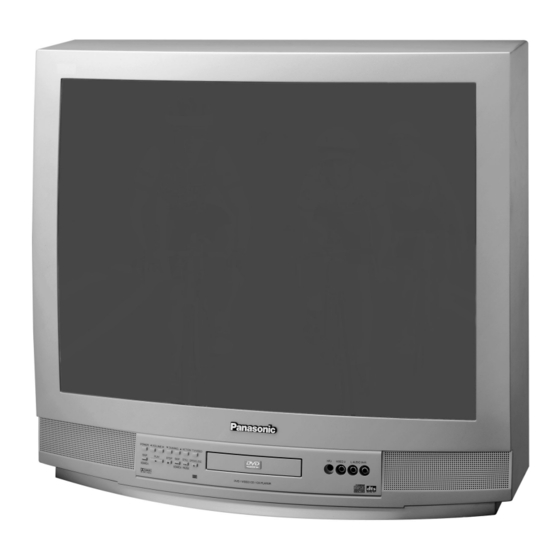
Receiver Feature Table FEATURE FEATURE Surround Chassis NA6DVD Built-in audio power 5Wx2 (10%) Tunning system # of speakers # of channels A/V in (rear/front) 2(2/1) Menu language English S-VHS Input (rear/front) Closed Caption Audio Out V-Chip (FAO & VAO) 75 Ω input Digital Optical Output Remote Model # EUR511503... - Page 7 Location of Controls (Receiver) Input Jacks 8 9 10 11 Remote Control Sensor Figure 2. Location of Controls Quick Reference Control Operation Quick Reference Control Operation Power Button - Press to turn ON or OFF. Volume Buttons - Press to adjust Sound Level, or to adjust Audio Menus, Video Menus, and select operating features when menus are displayed.
- Page 8 Quick Reference Control Operation Skip/Search - Press to search all channels/tracks. Play - Play DVD/CD. Stop - Stop playing DVD/CD. Skip/Search - Skip or search DVD/CD. Still/Pause - Pause DVD/CD while viewing. Open/Close - Open or close DVD drawer. - 8 -...
-
Page 9: Location Of Controls (Receiver & Dvd Player)
Location of Controls EMOTE ONTROL POWER Press to turn ON and OFF. LIGHT Press to light remote control buttons. TV DVD CBL/DBS VCR Press to select remote operation. ACTION* Press to access menu or enter selections Press to adjust TV sound and navigate in menus. -
Page 10: Receiver Exploded View
Receiver Exploded View Figure 4. Receiver Exploded View LOCATION OF COMPONENTS CABINET FRONT A-BOARD TRAY PANEL BACK COVER CHASSIS RAIL (L & R) PANASONIC BADGE A-V REAR BRACKET M-BOARD MOUNT METAL FRONT SPEAKER P-BOARD MOUNT METAL REAR BUTTONS K-BOARD DVD BRACKET... -
Page 11: Disassembly For Service
Disassembly for Service Back Cover C-Board - CRT Output Socket plugs onto the CRT neck. Remove all the screws marked with an arrow( from the back of the Receiver. • 3 screws at the top edge of the Receiver. • 1 screw at each lower corner of the Receiver. -
Page 12: K Board - Customer Controls
K-Board - Customer Controls (Keyboard Speakers Push Button Assembly) Speakers are secured to the cabinet’s front with 4 screws. Fastened to the inside of the cabinet front with 3 screws. The push button unit is attached to the Disassembly for CRT Replacement K-Board with 4 snap tabs (spring action). -
Page 13: Dvd Replacement
DVD Replacement Note: Observe universal STATIC PRECAUTIONS when handling the DVD unit. Replace the DVD unit when it fails (DVD unit is not Shipping shipped with the enclosure). When installing a new Grounding DVD, note the order of disassembly, and save the “Plug”... - Page 14 Tabs at the front end of the A-board Right Chassis Rail Detail Left Chassis Rail Detail To remove the rails, the DVD bracket and the A-Board press on the release tabs, and pull forward. To release each chassis rail from the DVD bracket, pull on the tabs Figure 14.
- Page 15 Disassembly for Service (Continued) Rear Front Figure 15. Receiver Internal View LOCATION OF COMPONENTS INTEGRATED CIRCUITS BOARDS TRANSISTORS VARIOUS IC 001 MPU A BOARD Q501 HOR. T551 (FLYBACK) IC 002 EEPROM C BOARD Q551 HOR. A/V JACKS IC 101 VCJ JJ BOARD FUSE (F801) IC 6501 3L FILTER...
- Page 16 Disassembly for Service (Continued) G-Board Installation Verify that when the cables leading from the A-Board to the G-Board are replaced, the ferrite beads are installed. See Fig. 16. G-Board Ferrite Bead Figure 16. G-Board Cables & Ferrite Beads Assembly IMPORTANT NOTE: Reuse hardware (screws,...
-
Page 17: Chassis Service Adjustment Procedures
Chassis Service Adjustment Procedures All service adjustments are factory preset and should not require adjustment unless controls and/or associated components are replaced. Note: Connect the (-) lead of the voltmeter to the appropriate ground. Use IC803’s heat sink when the HOT ground symbol ( ) is used. -
Page 18: Purity And Convergence Procedures
Purity and Convergence Procedure Adjustment is necessary only if the CRT or the For a 1-piece assembly (see Fig. 21): deflection yoke is replaced or if the setting was Position like tabs of purity devices together at 12 disturbed. The complete procedure consists of: o’clock to reduce any magnetic field effect. - Page 19 Initial Center Static Convergence Slowly move the deflection yoke and purity rings assembly toward the CRT board and adjust the purity Connect a dot/cross hatch generator to the Receiver magnet rings to set vertical green raster at center of and tune in a signal. Observe misconvergence at screen (see Fig.
- Page 20 As the yoke is tilted vertically, the rasters produced outside guns rotate in opposite directions. Figure 24. Vertical Yoke Movement Raster produced from one of the outside electron beams Raster from the other side electron beam R G B Static convergence magnets are set for center convergence As the yoke is tilted horizontally, one raster gets larger while the other gets...
-
Page 21: Serviceman Mode (Electronic Controls)
Serviceman Mode (Electronic Controls) This Receiver has electronic technology using the I²C Bus Concept. It performs as a control function and it replaces many mechanical controls. Instead of adjusting mechanical controls individually, many of the control functions are now performed by using “On Screen Display Menu”. (The Serviceman Adjustment Mode.) Note: It is suggested that the technician reads all the way through and understand the following procedure for Entering/Exiting the Serviceman Adjustment Mode;... -
Page 22: Sub-Data Adjustment
Press the Power Button on the Remote Control to select the Serviceman Adjustment . For Adjustments: 1.Press Channel Up/Down on the Note: Write Down the original 2.Press Volume Up/Down on the value set (b in Fig. 27 ) for Remote Control to select one of Remote Control to adjust the each address... -
Page 23: Options Adjustment
Press the Power Button on the Remote Control to select the Serviceman Adjustment For Adjustments: 1.Press Channel Up/Down on the Note: Write Down the original 2.Press Volume Up/Down on the value set (b in Fig. 27 ) for Remote Control to select one of Remote Control to adjust the the available Service Adjustments each... -
Page 24: Comb Filter Adjustment
Press the Power Button on the Remote Control to select the Serviceman Adjustment For Adjustments: 1.Press Channel Up/Down on the Note: Write Down the original 2.Press Volume Up/Down on the Remote Control to select one of value set (b in Fig. 27 ) for Remote Control to adjust the the available Service Adjustments each... -
Page 25: To Check Purity
To Check Purity: Press the Recall Button on the Remote Control when in Serviceman Mode (red “CHK” is displayed) to enter the Purity Field Check Mode. NORMAL SCREEN Press Recall again to select desired field. BLUE GRN. WHITE SCREEN SCREEN SCREEN SCREEN Figure 28. -
Page 26: Instructional Flow Chart For Serviceman Mode
Instructional Flow Chart for Serviceman Mode IMPORTANT NOTE: Always Exit the Serviceman Mode Following Adjustments. NORMAL MODE Momentarily short FA1 to FA2 ( AGING MODE • Yellow “CHK” appears in upper left corner of screen. WHITE • Volume Up/Down operate rapidly. SCREEN •... - Page 27 Instructional Flow Chart for Serviceman Mode - Continued LOUDNESS COMPENSATION (ON REMOTE) VCJ TEST PIP TINT CUT-OFF ADJUSTMENTS. BEAM LIMIT CLOCK C ITEMS. ADJUSTMENT HORIZ CENTER FREERUN YNR VID ADJ Adj. RIGH 1/16 RF-AGC needed? LEFT 1/16 DOWN 1/16 YNR SWITCH UP 1/16 (ON REMOTE) DRIVE B...
-
Page 28: Service Adjustments
Service Adjustments (Electronic Controls) Sub-Brightness Preparation: 1. Apply a color bar signal pattern with 87.5% Serviceman DAC Adjustment (B2) modulation, 70% saturated color bar with a 100 Adjustment of this control is important for setting proper IRE white and 7.5 black. operation of customer brightness and picture controls. -
Page 29: Color Temperature Adjustment
Service Adjustments (Electronic Controls, cont.) Procedure: • C3 ... 64 • C4 ... 64 1. In the Serviceman Mode for making electronic 1. -
Page 30: Horizontal Centering
Service Adjustments (Electronic Controls, cont.) Input Level Adjustment (M0) 20. In the Serviceman Mode for making electronic adjustments select the DAC DRIVE adjustments Preparation: (C3) RED, (C4) BLUE and adjust for warm white in 1. Connect an RMS meter with filter jig as shown in a white color bar pattern. -
Page 31: Clock Adjustment (Sb)
Service Adjustments (Electronic Controls, cont.) Clock Adjustment (Sb) 5. Calculate based Preparation: following formula: Connect the frequency counter from TPS1 (IC001 Pin 13) to cold ground ( 244.1406 pin 13 Hz – ×10 Note: Frequency Counter probe capacitance should 0.901 ----------------------------------------------------------------- - 244.1406 be 8pF or less. -
Page 32: Audio Signal Path Block Diagram
Audio Signal Path Block Diagram Figure 39. Audio Signal Path Block Diagram - 32 -... -
Page 33: Video-Chroma Signal Path Block Diagrams
Video-Chroma Signal Path Block Diagram Figure 40. Video-Chroma Path Block Diagram - 33 -... -
Page 34: Sync Path Block Diagram
Sync Signal Path Block Diagram Figure 41. Sync Signal Path Block Diagram - 34 -... - Page 35 IC101 IN/OUT Pins and Functions (VCJ) IC101 AN5166K V OUT CW OUT Ys & Ym H. OUT R IN HOLD DOWN G IN H. OSC B IN H. AFC VCJ (9 V) H. VCC R OUT FBP IN G OUT VCJ GND B OUT C IN...
- Page 36 IC001 IN/OUT Pins and Functions (MPU) IC001 MN1876476TC1 Remote signal in AFC 1 Tuner 1 12 MHz Xtal AFC 2 Tuner 2 12 MHz Xtal Lock detect + 5V Key in Action/HHS Version S-VHS input detect V-pulse (neg) Shutdown Reset TV/V PV1 Test OSC DVD PV3...
- Page 37 REPLACEMENT PARTS LIST Model: CT-27DC50B Important Safety Notice: Components printed in BOLD TYPE have special characteristics important for safety. When replacing any of these components use only manufacturer’s specified parts. REF NO. PART NO. DESCRIPTION REF NO. PART NO. DESCRIPTION...
- Page 38 REPLACEMENT PARTS LIST Model: CT-27DC50B Important Safety Notice: Components printed in BOLD TYPE have special characteristics important for safety. When replacing any of these components use only manufacturer’s specified parts. REF NO. PART NO. DESCRIPTION REF NO. PART NO. DESCRIPTION C564 ECWH16272JVY CAP,P 2700PF-J-1.5KV...
- Page 39 REPLACEMENT PARTS LIST Model: CT-27DC50B Important Safety Notice: Components printed in BOLD TYPE have special characteristics important for safety. When replacing any of these components use only manufacturer’s specified parts. REF NO. PART NO. DESCRIPTION REF NO. PART NO. DESCRIPTION...
- Page 40 REPLACEMENT PARTS LIST Model: CT-27DC50B Important Safety Notice: Components printed in BOLD TYPE have special characteristics important for safety. When replacing any of these components use only manufacturer’s specified parts. REF NO. PART NO. DESCRIPTION REF NO. PART NO. DESCRIPTION...
- Page 41 REPLACEMENT PARTS LIST Model: CT-27DC50B Important Safety Notice: Components printed in BOLD TYPE have special characteristics important for safety. When replacing any of these components use only manufacturer’s specified parts. REF NO. PART NO. DESCRIPTION REF NO. PART NO. DESCRIPTION...
- Page 42 REPLACEMENT PARTS LIST Model: CT-27DC50B Important Safety Notice: Components printed in BOLD TYPE have special characteristics important for safety. When replacing any of these components use only manufacturer’s specified parts. REF NO. PART NO. DESCRIPTION REF NO. PART NO. DESCRIPTION...
- Page 43 REPLACEMENT PARTS LIST Model: CT-27DC50B Important Safety Notice: Components printed in BOLD TYPE have special characteristics important for safety. When replacing any of these components use only manufacturer’s specified parts. REF NO. PART NO. DESCRIPTION REF NO. PART NO. DESCRIPTION...
- Page 44 REPLACEMENT PARTS LIST Model: CT-27DC50B Important Safety Notice: Components printed in BOLD TYPE have special characteristics important for safety. When replacing any of these components use only manufacturer’s specified parts. REF NO. PART NO. DESCRIPTION REF NO. PART NO. DESCRIPTION...
- Page 45 REPLACEMENT PARTS LIST Model: CT-27DC50B Important Safety Notice: Components printed in BOLD TYPE have special characteristics important for safety. When replacing any of these components use only manufacturer’s specified parts. REF NO. PART NO. DESCRIPTION REF NO. PART NO. DESCRIPTION...
- Page 46 REPLACEMENT PARTS LIST Model: CT-27DC50B Important Safety Notice: Components printed in BOLD TYPE have special characteristics important for safety. When replacing any of these components use only manufacturer’s specified parts. REF NO. PART NO. DESCRIPTION REF NO. PART NO. DESCRIPTION...
- Page 47 DESCRIPTION OF ABBREVIATIONS GUIDE RESISTOR TYPE TOLERANCE Carbon ± 1% Fuse ± 5% Metal Oxide ± 10% Solid ± 20% Wire Wound ± 2% RES, C 270-J-1/4 CAPACITOR TYPE TOLERANCE Ceramic ± 0.25pF Electrolytic ± 0.5pF Polyester ± 1pF Styrol ±...
- Page 48 SERVICEMAN MODE (ELECTRONIC CONTROL) SERVICE ADJUSTMENT VALUES Model _____________________________________________ Ser #_____________ Date_________________ Note: Record the original settings PRIOR to modifying the registers. Service Adjustment Def. Original Service Adjustment Def. Original Mode Mode Adjustment Range Val. Value Value Adjustment Range Val. Value Value Sub Adjustments...
- Page 49 A-Board Schematic (Left Portion) Boards Designation Voltage Measurements Schematic Notes Waveform Measurements Voltage measurement: Voltage readings are nominal Resistors are carbon 1/4W unless (BOLD LINE) indicates indicates waveform measurement. All video and color waveforms are • A-Board - Main Chassis and may vary ±10% on active noted otherwise.
-
Page 50: C-Board
A-Board Layout C-Board Layout TNPH0353 TNP2AA047 G-Board Layout TNPA1736 G-Board Schematic C-Board Schematic Notes: above boards have been modified to enhance and display traces otherwise hidden by a mask. Check Parts List for most recent component values and part numbers. Obtain voltages with... - Page 51 A-Board Schematic (Right Portion) A-Board Voltage Measurements (ICs and Transistors) IC001 IC101 ..4.41 ..0.00 ..2.86 ..n.c ..2.44 .
-
Page 52: M-Board
P-Board Layout M-Board Layout M-Board Voltages TNPA1738 TNPA1734 IC3502 IC3501 ..4.96 ..4.96 ..2.47 ..3.27 ..1.00 . - Page 53 JJ-Board Layout W-Board Layout W-Board Schematic JJ-Board Voltages TNPA1804 TNPA1735 IC3603 IC3001 IC3002 IC3601 IC3602 ..n.c ..GND ..4.00 ..0.00 .