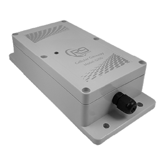
Summary of Contents for R9 Technology G200
- Page 1 User Guide G200 Gateway Hardware User Guide October 2020 Release 1.5 R9 Technology 17217 Waterview Parkway Suite 1.202Y Dallas, TX 75252 www.r9technology.com Copyright © 2020 R9 Technology Inc. All rights reserved.
- Page 2 User Guide Document Revisions Version Date Document Changes Number 06/10/2020 R1.4 First release of the document 10/15/2020 R1.5 Entry of IMEI/SN into portal, change to last 5 digits. Update G200 temp range. Copyright © 2020 R9 Technology Inc. All rights reserved.
-
Page 3: Table Of Contents
Power ..................................... 8 Interfaces, Indicators and Buttons ........................9 Installation ................................12 Dimensions ................................13 Sales and Warranty Policy ..........................13 Specifications ................................14 Certifications - United States FCC Statement ..................... 15 Copyright © 2020 R9 Technology Inc. All rights reserved. -
Page 4: Introduction
R9 web-based system. An LTE carrier SIM card is installed into the G200 at the factory. The G200 is powered on, by plugging it into an AC power outlet (120V, 60 Hz.). The device will initialize, and then immediately connect to the LTE network, local to your area. -
Page 5: G200 Product Label
This product label is shown in the picture below. 1. The IMEI ID, circled in red, in the picture below, is unique to each G200 device. The last 5 digits of the IMEI ID will be entered into the online portal system during setup, and is used to identify the G200. - Page 6 The standard G200 model number is G200-HACAAAC. This part number indicates: H – Optional features: no optional features are provisioned (GPS, Accelerometer, BLE radio, digital expansion port). A(1) – Antenna configuration: all system antennas are internal and PCB mounted.
-
Page 7: Wireless Operating Bands (Antennas)
The G200 915 Mhz antenna is PCB mounted and located internally to the enclosure. Note that it is possible to connect an external antenna to the G200 device. This is supported only as an option, and should not be necessary in a typical application. -
Page 8: Power
The battery is 3.7V, 2600 mAh (milli-Ampere hour), and will allow the G200 to continue to function if the unit is un-plugged, or AC building power is lost. This battery is not accessible by the customer. The G200 battery powered back-up time duration is dependent on several factors. -
Page 9: Interfaces, Indicators And Buttons
3 – After a few seconds, the LED will change to solid RED. The G200 has actually closed all devices and restarted (re-booted). While the LED is still RED, “quick press” the reset button again. The G200 will now power itself off, and the LED indicator will turn off. - Page 10 (LED out) between stages. The two-stage gateway LED indication sequence loops continuously. Note that during G200 gateway initialization, the LED will at first display red until the G200 processor sets the LED Copyright © 2020 R9 Technology Inc. All rights reserved.
- Page 11 Then the LED will display solid green for a few seconds. Once the G200 is initialized properly, the LED flash status will loop continuously as indicated in the table below. Gateway LED Stage 1: LTE Connection status (starts after long LED out...
-
Page 12: Installation
If the gateway is installed out-doors, make sure it is not installed in direct sunlight. Install the gateway in a dry, shaded area such as under the eaves of a building. I shade is not available, then the G200 gateway should be installed under a solar shade covering accessory. -
Page 13: Dimensions
7 Dimensions The dimensions of the G200 gateway are shown below. All Dimensions are shown in millimeters (mm). 8 Sales and Warranty Policy Please download the Sales Warranty Policy document from our website at www.r9technology.com. It is located on the “Resources/Documentation” web page. -
Page 14: Specifications
Optional 915 MHz external antenna (using MMCX connector) Optional USB 2.0 high-speed port cable for data transfer and/or 5V power input Optional RS232 / serial port cable Copyright © 2020 R9 Technology Inc. All rights reserved. -
Page 15: Certifications - United States Fcc Statement
This equipment should be installed and operated with a minimum distance of 20cm between the radiator and all persons. This transmitter must not be co-located or operating in conjunction with any other antenna or transmitter. Copyright © 2020 R9 Technology Inc. All rights reserved.


